1
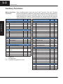
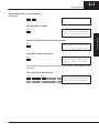
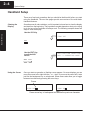
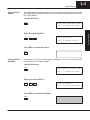
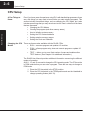
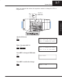
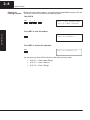
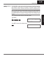
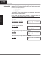
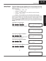
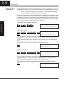
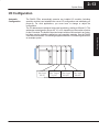
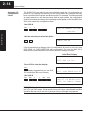
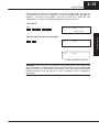
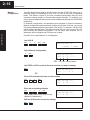
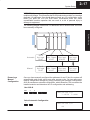
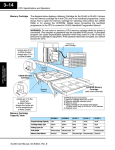
System Setup
12
2–2
System Setup
Auxiliary Functions
What are Auxiliary
Functions?
Many Handheld tasks involve the use of AUX Functions. The AUX Functions
perform many different operations, ranging from simple operating mode changes to
copying programs to memory cartridges. These functions are discussed in more
detail throughout the manual. They are divided into categories that affect different
system parameters. You’ll use AUX Functions for the following types of operations.
AUX Function and Description
DL430 DL440
System Setup
AUX 1* — Operating Mode
DL430 DL440
AUX 5* — CPU Configuration
11
Go to Run Mode
m
m
51
Modify Program Name
m
m
12
Go to Test Mode
m
m
52
Display / Change Calendar
5
m
13
Go to Program Mode
m
m
53
Display Scan Time
m
m
14
Run Time Edit
5
m
54
Initialize Scratchpad
m
m
55
Set Watchdog Timer
m
m
AUX 2* — RLL Operations
21
Check Program
m
m
56
Set CPU Network Address
m
m
22
Change Reference
5
m
57
Set Retentive Ranges
m
m
23
Clear Ladder Range
m
m
58
Test Operations
m
m
24
Clear Ladders
m
m
5C
Display Error History
5
m
AUX 3* — V-Memory Operations
AUX 6* — Handheld Programmer Configuration
31
Clear V Memory
m
m
61
Show Revision Numbers
m
m
32
Clear V Range
m
m
62
Beeper On / Off
HP
HP
33
Find V-memory Value
5
m
63
Backlight On / Off
HP
HP
64
Select Online / Offline
HP
HP
65
Run Self Diagnostics
HP
HP
AUX 4* — I/O Configuration
m
AUX Function and Description
41
Show I/O Configuration
m
m
42
I/O Diagnostics
m
m
44
Powerup I/O Configuration
Check
m
m
45
Select Configuration
m
m
46
Configure I/O
5
m
47
Intelligent I/O
m
m
— supported
5 — not supported
HP — Handheld Programmer function
AUX 7* — Memory Cartridge Operations
71
CPU to Memory Cartridge
m
m
72
Memory Cartridge to CPU
m
m
73
Compare Memory Cart. to CPU
m
m
74
Memory Cartridge Blank Check
HP
HP
75
Clear Memory Cartridge
HP
HP
76
Display Memory Cartridge Type
m
m
77
Tape to Memory Cartridge
HP
HP
78
Memory Cartridge to Tape
HP
HP
79
Compare Memory Cart. to Tape
HP
HP
AUX 8* — Password Operations
81
Modify Password
5
m
82
Unlock CPU
5
m
83
Lock CPU
5
m
System Setup
2–3
Accessing the AUX Clear the display
Functions
CLR
CLR
Select Auxiliary function
AUX
AUX FUNCTION SELECTION
AUX 1* OPERATING MODE
NXT
AUX FUNCTION SELECTION
AUX 2* RLL OPERATIONS
Press ENT to select sub-menus
ENT
AUX 2* RLL OPERATIONS
AUX 21 CHECK PROGRAM
You can also enter the exact number of the AUX Function to go straight to the
sub-menu.
Enter the AUX number directly
AUX
2
1
ENT
AUX 2* RLL OPERATIONS
AUX 21 CHECK PROGRAM
System Setup
Use NXT or PREV to cycle through the menus
2–4
System Setup
Handheld Setup
There are a few basic operations that you should be familiar with before you start
using the Handheld. The next few pages provide an overview of the most basic
Handheld features.
Clearing the
Display
Sometimes we all make mistakes, so it’s important to know how to clear the display
and start from the beginning. The keystrokes needed depend on what you’re trying
to do, but one of two methods will always work. The following example shows two
ways to clear the display.
System Setup
Use the CLR Key
STRN X41
CLR
Use the EXIT Key
to exit the AUX
menus
SHFT
Using the Cursor
AUX FUNCTION SELECTION
AUX 1* OPERATING MODE
EXIT
Once you start an operation, a flashing cursor appears. On some displays you can
move this cursor left or right with the ← or → keys. If you move the cursor left, it acts
just like the backspace key on a keyboard. Some menus also allow you to toggle
between two choices by pressing the arrow keys.
Cursor
STRN X41
STRN X4
Press arrow key to backspace and delete the previous character
System Setup
Turning Off the
Beeper
2–5
The Handheld has a beeper that provides confirmation of keystrokes. This can be
quite annoying in an office environment. You can use Auxiliary (AUX) Function 62 to
turn off the beeper.
Use the AUX menu
AUX
AUX FUNCTION SELECTION
AUX 1* OPERATING MODE
6
2
AUX 6* CFG MIU
AUX 62 BEEPER ON/OFF
Press ENT to turn off the beeper
ENT
Turning Off the
Backlight
If necessary, you can turn off the display backlight. You can use Auxiliary (AUX)
Function 63 to turn off the backlight.
Use the AUX menu
AUX
AUX FUNCTION SELECTION
AUX 1* OPERATING MODE
Enter 63 to select AUX 63
6
3
Press ENT to turn off the backlight
ENT
AUX 6* CFG MIU
AUX 63 BACKLIGHT ON/OFF
System Setup
Enter 62 to select AUX 62
2–6
System Setup
System Setup
CPU Setup
A Few Things to
Know
Even if you have years of experience using PLCs with handheld programmers, there
are a few things you may need to know before you start entering programs. This
section includes some basic things, such as changing the CPU mode, but it also
includes some things that you may never have to use. Here’s a brief list of the items
that are discussed.
S Changing the CPU Modes
S Clearing the program (and other memory areas)
S How to initialize system memory
S Setting the CPU network address
S Setting retentive memory ranges
S Setting the Clock and Calendar
Changing the CPU
Modes
There are three modes available with the DL405 CPUs.
S RUN — executes program and updates I/O modules
S PGM — allows program entry, does not execute program or update I/O
modules
S TEST — allows you to run a fixed number of scans and enables other
TEST features. (See Chapter 6 for additional information.)
The DL405 User Manual provides additional information concerning the different
modes of operation.
AUX 11, 12, and 13 are used to change the CPU operating mode. The CPU must be
in PGM mode before you can enter a program. There are two ways to change to
PGM mode.
1. Place the CPU keyswitch in the STOP position.
2. Place the CPU keyswitch in the TERM position and use the Handheld to
change operating modes (AUX 13).
System Setup
2–7
Here’s an example that shows the keystrokes needed to change the CPU to
Program mode.
RUN
TERM
Keyswitch in
TERM mode
for HPP control
STOP
System Setup
Use the AUX menu
AUX
AUX FUNCTION SELECTION
AUX 1* OPERATING MODE
Enter 13 to select AUX 13
1
3
AUX 1* OPERATING MODE
AUX 13 GO TO PGM MODE
Press ENT to change to PGM mode
ENT
PGM MODE?
Press ENT to confirm the change
ENT
MODE = PGM
2–8
System Setup
Clearing an
Existing Program
Before you enter a new program, you should always clear ladder memory. You can
use AUX Function 24 to clear the complete program.
Use AUX 24
AUX
2
4
AUX 2* RLL OPERATIONS
AUX 24 CLEAR LADDERS
System Setup
Press ENT to clear the ladders
CLR ALL LADDERS ?
Press ENT to confirm the operation
ENT
CLR ALL LADDERS OK
You can also use other AUX functions to clear other memory areas.
S
S
S
AUX 23 — Clear Ladder Range
AUX 31 — Clear V Memory
AUX 32 — Clear V Range
System Setup
Initializing System
Memory
2–9
The DL405 CPUs maintain system parameters in a memory area often referred to as
the “scratchpad”. In some cases, you may make changes to the system setup that
will be stored in system memory. For example, if you specify a range of Control
Relays (CRs) as retentive, these data values will be stored in scratchpad memory.
NOTE: You may never have to use this feature unless you have made changes that
affect system memory. Usually, you’ll only need to initialize the system memory if you
are changing programs and the old program required a special system setup. You
can usually change from program to program without ever initializing system
memory.
AUX 54 resets the system memory to the default values.
AUX
5
4
AUX 54 INIT SCRATCH PAD
CLR XPAD?
Press ENT to return to the default values
OK
System Setup
Use AUX 54
2–10
System Setup
Setting the CPU
Network Address
Since the DL405 CPUs have built-in Direct NET ports (25-pin), you can use the
Handheld to set the network address for the port and the port communication
parameters. The default settings are:
S Station address 1
S Hex mode
S Odd parity
The Direct NET manual provides additional information about communication
settings required for network operation.
System Setup
NOTE: You will only need to use this procedure if you have the bottom port
connected to a network, operator interface or personal computer.
Use AUX 56 to set the network address and communication parameters.
Use AUX 56
AUX
5
6
ENT
ENT
AUX 56 CPU N/W ADDRESS
N/W #
01
Enter the new station address
0
3
ENT
AUX 56 CPU N/W ADDRESS
HEX / ASCII
Use the arrow keys to toggle between the settings
ENT
AUX 56 CPU N/W ADDRESS
NONE / ODD
Use the arrow keys to toggle between the settings
ENT
AUX 56 CPU N/W ADDRESS
OK
System Setup
Setting Retentive
Memory Ranges
2–11
Use AUX 57 to set the ranges
AUX
5
7
ENT
ENT
AUX 57 SET RET RANGES
1st C0600
(One of two types of displays will appear.)
Display with existing range
AUX 57 SET RET RANGES
1st C––––
Display without an existing range
Enter the first retentive CR address
6
3
0
ENT
(Except for V Memory, all ranges must be
entered in 8-bit increments.)
AUX 57 SET RET RANGES
END C0737
Enter the last retentive CR address
6
5
0
ENT
AUX 57 SET RET RANGES
1st V02000
Enter the first retentive V-Memory address
3
5
0
0
ENT
AUX 57 SET RET RANGES
END V07777
D
D
D
D
D
D
END
System Setup
The DL405 CPUs provide certain ranges of retentive memory by default. The default
ranges are suitable for many applications, but you can change them if your
application requires additional retentive ranges or no retentive ranges at all. The
default settings are:
S Control Relays — C600 – C737
S V Memory — V2000 – V7377
S Timers — None by default (you can make them retentive though)
S Counters — CT0 – CT177
S Stages — None by default (you can make them retentive though)
Use AUX 57 to change the retentive ranges. You cannot select an individual memory
type to change. Instead, you must cycle through the retentive range for each
memory type. If you do not want to change the starting or ending address for one of
the memory types, just press ENT to leave the entry as is. If you make a mistake, you
can press SHFT DEL to return the memory type currently displayed to the default
settings.
2–12
System Setup
Setting the Clock
and Calendar
The DL440 CPU has a clock and calendar feature. If you are using this, you can use
the Handheld and AUX 52 to set the time and date. The following format is used.
S Date — Year, Month, Date, Day of week (0 – 6, Sunday thru Saturday)
S Time — 24 hour format, Hours, Minutes, Seconds
You can use the AUX function to change any component of the date or time.
However, the CPU will not automatically correct any discrepancy between the date
and the day of the week. For example, if you change the date to the 15th of the month
and the 15th is on a Thursday, you will also have to change the day of the week
(unless the CPU already shows the date as Thursday).
System Setup
Use AUX 52 to set the time and date
AUX
5
2
ENT
ENT
AUX 52 CHG CLOCK / CAL
YMD 94/01/01/6(SAT)
Enter the new date
9
4
0
1
0
2
0
ENT
AUX 52 CHG CLOCK / CAL
YMD 94/01/02/0(SUN)
(You can also use the arrow keys to move the cursor over the exact part you
need to change. Or, if you don’t need to change the date you can just press
ENTER without changing any numbers to leave the date as is and change the
time.)
Press Enter to accept the new date and display the time
ENT
AUX 52 CHG CLOCK / CAL
TIME 22:08:17
Enter the new time
2
3
0
8
1
7
ENT
AUX 52 CHG CLOCK / CAL
TIME 23:08:17
(You can also use the arrow keys to move the cursor over the exact part you
need to change. Or, if you don’t need to change the time you can just press
ENTER without changing any numbers to leave the time as is.)
Press Enter to accept the changes and display the new date and time
ENT
94/01/02 23:08:17
System Setup
2–13
I/O Configuration
Automatic
Configuration
Slot 0
Slot 1
Slot 2
Slot 3
8pt. Input
32pt. Output 16pt. Input
8pt. Input
X0-X7
Y0-Y37
X10-X27
X30-X37
Automatically compensates for I/O types
System Setup
The DL405 CPUs automatically examine any installed I/O modules (including
specialty modules) and establish the correct I/O configuration and addressing on
power-up. For most applications, you never have to change or adjust the
configuration.
The I/O addresses are assigned using octal numbering, starting at X0 and Y0. The
addresses are assigned in groups of 8, 16, or 32, depending on the number of points
for the I/O module. The discrete input and output modules can be mixed in any order,
but there may be restrictions placed on some specialty modules. See the DL405
User Manual for details. The following diagram shows the I/O numbering scheme for
an example system.
2–14
System Setup
Automatic I/O
Configuration
Check
The DL405 CPUs can also be set to automatically check the I/O configuration on
power-up. By selecting this feature you can quickly detect any changes that may
have occurred while the power was disconnected. For example, if someone placed
an output module in a slot that previously held an input module, the configuration
check would detect the change and a message would appear on the Handheld. Use
AUX 44 to enable the configuration check.
Use AUX 44
System Setup
AUX
4
4
AUX 44 POWERUP CFG CHK
(YES/NO)
Use the arrow key to select the option
PWRUP CHK ON
If the system detects a change in the I/O configuration at power-up, an error code
E252 NEW I/O CONFIGURATION will be generated. You can use AUX 42 to
determine the exact base and slot location where the change occurred.
Initial Error Display
E252 NEW I/O CFG
Press CLR to clear the display
CLR
(The display suggests that you use AUX
42 to determine the error location.)
E2** DIAG ERROR AUX 42
Use AUX 42
CLR
AUX
4
2
ENT
ENT
AUX 42 I/O BASE0/SLOT1
E252 I/O CONFIG. ERROR
WARNING: You should always correct any I/O configuration errors before you place
the CPU into RUN mode. Uncorrected errors can cause unpredictable machine
operation that can result in a risk of personal injury or damage to equipment.
System Setup
2–15
Even though an error was generated, you may actually want the new I/O
configuration to be used. For example, you may have intentionally changed the
module to use with a new program. You can use AUX 45 to select the new
configuration, or, keep the existing configuration stored in memory.
Use AUX 45
AUX
4
5
AUX 45 SELECT CFG
(NEW/MEM)
CFG
NEW
New configuration selected
CFG
MEM
Existing configuration selected
WARNING: Make sure the I/O configuration being selected will work properly with
the CPU program. You should always correct any I/O configuration errors before you
place the CPU into RUN mode. Uncorrected errors can cause unpredictable
machine operation that can result in a risk of personal injury or damage to
equipment.
System Setup
Use the arrow key to select the option
2–16
System Setup
System Setup
Manual
Configuration
You will probably never need to use this feature, but the DL440 CPU allows you to
manually assign I/O addresses for any or all I/O slots on the local or expansion
bases. This feature is useful if you have a standard configuration that you must
sometimes change slightly to accommodate special requests. For example, you
may require two adjacent input modules to have addresses starting at X10 and X200
respectively.
In automatic configuration, the addresses were assigned on 8-point boundaries.
Manual configuration assumes that all modules are at least 16 points, so you can
only assign addresses that are a multiple of 20 (octal). For example, X30 and Y50
would not be valid addresses. This does not mean that you can only use 16 or 32
point modules with manual configuration. You can use 8 point modules, but 16
addresses will be assigned and 8 of them are unused.
Use AUX 46 to select Manual I/O Configuration.
Use AUX 46
AUX
4
6
ENT
ENT
AUX 46 CFG I/O
1–>AUTO 2–>MAN
Select Manual Configuration
2
ENT
AUX 46 CFG I/O
0/0 X
0 ––––––
base
slot type starting address
Use PREV or NXT to scroll to the base and slot you want to change
NXT
AUX 46 CFG I/O
0/1 –––––– Y 0
OR
Press CLR and enter the base and slot number
CLR
0
2
NXT
AUX 46 CFG I/O
0/2 X 20 ––––––
Enter the new starting address
X(IN)
1
0
0
ENT
(The display scrolls to the next slot and
updates the addresses.)
Exit the AUX function to save the change
SHFT
EXIT
AUX 46 CFG I/O
0/3 X 20 ––––––
System Setup
2–17
WARNING: If you manually configure an I/O slot, the I/O addressing for the other
modules will change. This is because the DL405 products do not allow you to assign
duplicate I/O addresses. You should always correct any I/O configuration errors
before you place the CPU into RUN mode. Uncorrected errors can cause
unpredictable machine operation that can result in a risk of personal injury or
damage to equipment.
The following diagram shows how I/O addresses can be affected after a slot has
been manually configured.
System Setup
Removing a
Manual
Configuration
Once you have manually configured the addresses for an I/O slot, the system will
automatically retain these values even after a power cycle. You can remove any
manual configuration changes by simply performing an automatic configuration.
AUX 46 executes an automatic configuration, which allows the CPU to examine the
installed modules and determine the I/O configuration and addressing.
Use AUX 46
AUX
4
6
AUX 46 CFG I/O
1–>AUTO 2–>MAN
Select Automatic Configuration
1
AUX 46 CFG I/O
OK
2–18
System Setup
System Setup
Now that you understand the basics of the DL405 Handheld Programmer and how to
perform many different types of system setup operations, you are ready to enter a
program.