
1
GEORGIA
SET TOP BOX SPECIFICATION
14 June 2014
© Copyright 2014
Foreword
This Technical Specification was developed as an example of the digital TV receiver specification. It is based on
recognized International Standards documents.
This Technical Specification specifies the minimum and premium specifications to conform for the approval of
Digital Receiver (Set-Top-Box and Integrated Digital Television) .
Table of contents
2
1
1 Scope ...................................................................................................................................................................................... 7
1.1 Glossery ............................................................................................................................................................................... 8
2
2 References………………………………………………………………………………………………………………………………………………………… ............. 10
2.1 Overview ............................................................................................................................................................................ 11
3
3 Requirements ....................................................................................................................................................................... 11
3.1 General Requirements ....................................................................................................................................................... 11
3.1.1 Power supply .................................................................................................................................................................. 11
3.1.2 Power Supply Cord and Mains Plug ................................................................................................................................ 11
3.1.3 Electromagnetic Compatibility ....................................................................................................................................... 11
3.1.4 Elecrical Safety ................................................................................................................................................................ 11
3.1.5 Marking ........................................................................................................................................................................... 11
3.2 Technical Requirements .................................................................................................................................................... 12
3.2.1 Processor and Memory ................................................................................................................................................... 12
3.2.2 Services Summary ........................................................................................................................................................... 12
3.2.2.1 Time-exclusive Services ............................................................................................................................................... 12
3.2.3 Video decoding requirements ........................................................................................................................................ 12
3.2.3.1 Video Codec ................................................................................................................................................................. 12
3.2.3.2 Resolutions .................................................................................................................................................................. 12
3.2.3.3 Video Bitrates .............................................................................................................................................................. 13
3.2.3.4 Output Resolution Control for Set-Top-Boxes ............................................................................................................. 13
3.2.3.5 Widescreen .................................................................................................................................................................. 13
3.2.3.6 Primary Video Output .................................................................................................................................................. 13
3.2.3.7 Secondary Video Output .............................................................................................................................................. 13
3.2.3.8 High Definition Video Output and Display ................................................................................................................... 14
3.2.3.9 Copy Protection on outputs ......................................................................................................................................... 14
3.2.3.10 Down-conversion of High Definition Video for Standard Definition output ............................................................. 14
3.2.3.11 Display Format for other Aspect Ratios…………………………………………………………………………………………..........
3.2.4 Audio decoding requirements ........................................................................................................................................ 14
3.2.4.1 E-AC-3 and AC-3
Requirements on Audio Handling ....................................................................................................................................... 15
3.2.4.1.1 E-AC-3 andAC-3
All Pass-through, Decoding and Transcoding ..................................................................................................................... 15
3.2.4.1.2 E-AC-3 and AC-3
Metadata ............................................................................................................................................................................. 15
3.2.4.1.3. E-AC-3 and AC-3
Audio Output ....................................................................................................................................................................... 15
3.2.4.2 HE-AAC
Requirements on Audio Handling ....................................................................................................................................... 16
3.2.4.2.1 HE-AAC
All Pass-through, Decoding and Transcoding ...................................................................................................................... 16
3.2.4.2.2 HE-AAC
Metadata ............................................................................................................................................................................. 16
3.2.4.2.3 HE-AAC
Audio Output ....................................................................................................................................................................... 17
3.2.4.3. Decoding options ........................................................................................................................................................ 18
3.2.4.4 Analogue Phono Audio ................................................................................................................................................ 18
3.2.4.5 Digital Audio Output, S/PDIF and/or HDMI ARC (optionals) ........................................................................................ 18
3.2.5 Adjustment of Video/Audio-delay .................................................................................................................................. 18
3.2.6 HDMI Interface ............................................................................................................................................................... 19
3.2.6.1 General ........................................................................................................................................................................ 19
3.2.6.2 Video Output and Display ............................................................................................................................................ 19
3.2.7 Conditional Access (CA) .................................................................................................................................................. 19
3.2.7.1 General………………………………………………………………………………………………………………………………………………………………… 20
3.2.7.2 Common Interface ....................................................................................................................................................... 20
3.2.8 Tuner / Decoder .............................................................................................................................................................. 20
3.2.8.1 RF-PAL AND/OR SECAM Output (option)..................................................................................................................... 20
3.2.8.2 Requirements for the signal strength indicator (SSI) ................................................................................................... 20
3.2.8.3 Requirements for the signal quality indicator (SQI) .................................................................................................... 22
3.2.8.3.1 DVB-T2 signals .......................................................................................................................................................... 22
3.2.8.4 Changes In Modulation Parameters ............................................................................................................................ 23
3.2.8.5 RF Input Connector ...................................................................................................................................................... 23
3.2.8.6 RF Output Connector (option) ..................................................................................................................................... 24
3.2.8.7 Time Interleaving ......................................................................................................................................................... 24
3.2.8.8 Input/Output Data Formats ......................................................................................................................................... 24
3.2.8.9 Frequency Range & Bandwidth……………………………………………………………………………………………………………..25
3.2.8.10 DVB-T2 Operating Modes .......................................................................................................................................... 25
3.2.8.10.1 Multiple PLP Feature Requirements ....................................................................................................................... 25
3.2.8.11 Receiver DVB-T2 Performance Requirements ........................................................................................................... 26
3.2.8.11.1 Input Signal Level / Receiver Sensitivity ................................................................................................................. 27
3.2.8.11.2 Interference Immunity............................................................................................................................................ 27
3.2.8.11.3 Tolerance toEqual Amplitude SFN Signals .............................................................................................................. 28
3.2.8.11.4 Immunity to 800 MHz LTE signals in Other Channels ............................................................................................. 29
3.2.8.11.5 Time-Frequency Slicing (TFS) .................................................................................................................................. 30
3.2.8.11.6 Installation mode
Automatic Search, best service ........................................................................................................................................... 30
4
4 Service Information .............................................................................................................................................................. 31
4.1. General Requirements ...................................................................................................................................................... 31
4.1.1 PSI/SI Information ........................................................................................................................................................... 31
4.1.2 Scanning for Services ...................................................................................................................................................... 32
4.1.3 Service List ...................................................................................................................................................................... 32
4.1.3.1. Logical Channel Descriptor (LCD version 2) ................................................................................................................ 32
4.1.3.2 Chanel Numbering ....................................................................................................................................................... 33
4
4.1.3.3 Regional Broadcast Management ................................................................................................................................ 35
4.1.3.4 Network Evolution ....................................................................................................................................................... 37
4.1.3.5 Selection via Service List .............................................................................................................................................. 38
4.1.3.6 Hidden Services ........................................................................................................................................................... 38
4.1.3.7 Dynamic PSI/SI table handing ...................................................................................................................................... 38
4.1.4 EIT Information ............................................................................................................................................................... 38
4.1.4.1 EIT Present/Following (p/f) .......................................................................................................................................... 38
4.1.4.2 EPG "Schedule" ............................................................................................................................................................ 39
4.1.5 Clock................................................................................................................................................................................ 39
5
5 User Interface and Navigator ................................................................................................................................................ 39
5.1. General ............................................................................................................................................................................. 39
5.2 Language support .............................................................................................................................................................. 39
5.2.1 Subtitle Selection ............................................................................................................................................................ 40
5.2.2 Audio Selction ................................................................................................................................................................. 40
5.3 Receiver charecter set ....................................................................................................................................................... 40
5.4 Subtitling ............................................................................................................................................................................ 40
5.4.1 Subtitling subset ............................................................................................................................................................. 41
5.4.2 Desplay of Subtitles During Enhanced Programming (Hybrid Profile) ............................................................................ 42
5.5 Audio Prioritising ............................................................................................................................................................... 42
6
6 Conditional Access ................................................................................................................................................................ 43
6.1 General .............................................................................................................................................................................. 43
6.1.1 Receivers with embedded CAimplementation ............................................................................................................... 43
6.1.2 Receivers with Common Interface (IDTVs) ..................................................................................................................... 43
6.1.3. CI Plus CAM modules ..................................................................................................................................................... 43
7
7 Plug-in PVR ............................................................................................................................................................................ 44
8
8 User Preferences................................................................................................................................................................... 45
8.1 Stored preferences ............................................................................................................................................................ 45
8.2 Deleton of service lists ....................................................................................................................................................... 45
8.3 Reset to factory mode ....................................................................................................................................................... 45
9
9 Receiver accessories and packaging ..................................................................................................................................... 47
9.1 Easy to Use and Simple Documentation ............................................................................................................................ 47
9.2 Support Package ................................................................................................................................................................ 47
9.3 Remote Control.................................................................................................................................................................. 48
10
10 Maintenance & Upgrade .................................................................................................................................................... 49
5
10.1 Over-The-Air-Download ................................................................................................................................................... 49
10.2 User Software Upgrade ................................................................................................................................................... 49
10.3 Status……………………………………………………………………………………………………………………………………………………………………..... 50
6
INTRODUCTION
Proposition
This document outlines a receiver which is capable of receiving both Standard Definition and High Definition
Digital Terrestrial broadcast.
Items in this specification are divided into „Required‟ and „Optional‟ categories. Where a feature is stated as
„Required‟, its inclusion is necessary for the achievement of a minimum compliance with transmission
requirements. Additional Optional functions may be added by the vendor to enhance the consumer
proposition and these will be welcomed. In order to be compliant, where a feature is „Optional‟ and is
included in an offered receiver design, the optional feature must be implemented in accordance with the
associated referenced standards. The word “shall” implies that the item is a requirement (mandatory) while
the word “may” implies that a requirement is optional.
This specification is not a comprehensive list of all relevant standards relating to consumer equipment that can
provide digital terrestrial reception but rather a list of those standards considered relevant to requirements.
The profile is based upon open standards predominantly from Digital Video Broadcasting (DVB) standards and
ETSI.
Purpose
The purpose of this document is to describe the requirements for a certified Free to View Terrestrial receiver
and to refer to detailed specifications that are required for conformant implementation. The profile is in the
form of a hardware specification outline, together with an overview of software requirements. The software is
to be routinely capable of being upgraded via ”over-the-air download.
1 Scope
The document sets out to identify the baseline functional specification of a H.264 AVC HD digital terrestrial
receiver including both Set-Top-Boxes and IDTV‟s.
1. Basic Profile (BP)
Profile can be extended with “Plug-In PVR” features, in other words connecting a USB hard drive or similar to
terrestrial receiver for time-shifting or recording event(s) within a single transport stream.
Personal Video Recorders (PVRs) are outside the scope of this document. It is intended that a terrestrial
receiver conforming to this profile should comprise part of a domestic installation, in conjunction with an
external, fixed wideband terrestrial UHF/VHF antenna input. Set-Top-Box output(s) will connect to the
television display (and possibly other domestic equipment).
It is the aim of the specification to ensure that the approved receiver satisfies the minimum requirements of
each broadcaster.
7
1.1
Glossary
AFD
Active Format Descriptor
AC-3
Dolby Digital (5.1 Channel)
CVBS
Composite Video Blanking and Synchronization
BER
Bit Error Rate
C/N
Carrier to Noise Ration
CLUT
(DVB) Colour Look Up Table
CVBS
Composite Video Baseband Signal
DTT
Digital Terrestrial Television
DVB
Digital Video Broadcast organization
DVB-CI
DVB-Common Interface
DVB-T
DVB-Terrestrial
EBU
European Broadcasting Union
EPG
Electronic Programme Guide
EIT
Event Information Table
FEC
Forward Error Correction FFT Fast Fourier Transform
FTA
Free to Air
HDCP
High-Bandwidth Digital Content Protection
HDMI
High-Definition Multimedia Interface
HDTV
High Definition Television IRD
Integrated Receiver Decoder iDTVs
Integrated Digital Televisions MP@ML Main
Profile at Main Level
MPEG
8
Moving Pictures Expert Group
Must Indicates that a third party must comply to ensure correct operation (present tense) Is Indicates an
existing provision
NIT
Network Information Table
OSD
On Screen Display
(Opt)
Optional
PAL
Phase Alternating Line
QAM
Quadrature Amplitude Modulation
QPSK
Quadrature Phase Shift Keying
(Req)
Requirement
RF
Radio Frequency
RS
Reed-Solomon
SD
Standard Definition
SDT
(DVB) Service Description Table
SDTV
Standard Definition Television
SFN
Single Frequency Network
SI
Service Information
S/PDIF
Sony/Philips Digital Interface
SSU
System Software Update
STB
Set-Top-Box, which is equivalent to a digital Terrestrial receiver
Shall
Indicates a mandatory provision
Should
Indicates a desirable, but not mandatory, provision
(TS)
Transport Stream: A data structure defined in ISO/IEC 13818-1
UHF
Ultra-High Frequency
Y/C
S-Video Signal
YCbCr/YPbPr Component Video Signal
Will
9
Indicates an assumption about existing states or future events
2 References
[1]
HDMI “High-Definition Multimedia Interface; specification Version 1.4”
HDCP “High-Definition Digital Content Protection System Revision 1.4”
[2]
EN 300 468 V1.11.1 Digital Video Broadcasting (DVB) Digital Broadcasting Systems for Television,
Sound, and Data Services. Specification for service information (SI) in Digital Video Broadcasting (DVB)
European Telecommunication Standards Institute ETSI
[3]
TR 101 211 V1.7.1 Digital Video Broadcasting (DVB); guidelines on implementation and usage of
Service information(SI)
[4]
EN 302 755 Rev R1.1.1 Frame structure channel coding and modulation for a second generation digital
terrestrial television broadcasting system (DVB-T2)
[5]
ETR 101 154 v1.9.1 Digital Video Broadcasting (DVB); Implementation Guidelines for the use of video
and audio coding in Broadcasting Applications based on the MPEG-2 transport stream
[6]
ETSI 162 Digital Broadcasting Systems for Television, sound and data services, allocation of service
information (SI) codes for digital Video Broadcasting (DVB) systems. European Telecommunication
Standards Institute. ETSI.
[7]
ETSI 300 743 v1.3.1 Digital Video Broadcasting (DVB); DVB Subtitling Systems. European
Telecommunication Standards Institute. ETSI.
[8]
ISO/IEC 14496-10 2005 Information Technology – Coding of audio visual objects – part 10 –Advanced
Coding
[9]
NorDig Unified ver. 2.4 NorDig Unified Requirements for Integrated Receiver Decoders for use in
cable, satellite, terrestrial and IP-based networks.
[10]
CI Plus Specification. Content Security Extensions to the Common Interface. V1.3.
[11]
ETSI TS 102 006 Digital Video Broadcasting; Specification for System Software Update in DVB Systems.
V1.3.1
10
2.1
Overview
This specification uses as a reference a number of national and international standards from the DVB, ETSI, ISO
and other standardization bodies to create a Digital Broadcast profile. It does not intend to create a set of
unique specifications unless deemed necessary by the commercial realities.
3 Requirements
3.1
3.1.1
General Requirement
Power supply
The receiver may be AC or DC powered. For AC powered equipment, the operating voltage shall be 240 V +5 %,
-10 % and frequency 50 Hz ± 1 % as according to MS 406 or 230 V ± 10 % and frequency 50 Hz ± 1 % as
according to MS IEC 60038 whichever is current. (Req)
Where external power supply is used, e.g. AC adaptor, it shall not affect the capability of the receiver to meet
this specification. Adaptor must be pre-approved by the relevant regulatory body before it can be used with
the receiver. (Req)
3.1.2
Power Supply Cord and Mains Plug
The receiver shall be fitted with a suitable and appropriate approved power supply cord and mains plug. Both
are regulated products and must be pre-approved by the relevant regulatory body before it can be used with
the receiver. (Req)
The power supply cord shall be certified as according to:
a) MS 140; or
b) BS 6500; or
c) IEC 60227-5; or
d) IEC 60245-4.
3.1.3
Electromagnetic Compatibility
The receiver may comply with the EMC emissions requirements as defined in the MS CISPR 13 or equivalent
international standards. The requirements shall cover radiated and conducted emission. (Opt)
3.1.4
Electrical Safety
The receiver shall comply with the safety requirements as defined in MS IEC 60065. The supplier shall submit
full type test report of MS IEC 60065 or equivalent international standards. (Req)
3.1.5
Marking
The receiver shall be marked with the following information:
11
a) supplier/manufacturer‟s name or identification mark;
b) supplier/manufacturer‟s model or type reference; and
c) other markings as required by the relevant standards.
The markings shall be legible, indelible and readily visible. All information on the marking shall be either in
Georgian or English Language. (Req)
3.2
3.2.1
Technical Requirements
Processor and Memory
The processing power and memory configuration of the receiver must be suitable for the routine operation of
digital Terrestrial reception, (DVB-T2), together with the embedded operation of the interactive application
and the provision of the routine replacement of all software via “over-the-air download”.
3.2.2
Services Summary
The receiver must give access to all available digital terrestrial television and radioservices. This must include
the capability to efficiently present radio channels and DVB subtitles of all services. It must present DVB
subtitles when broadcasted and if requested by the viewer. Set -Top -Boxes shall also be able to manage the
output video in both widescreen 16:9 and 4:3 picture formats to suit the connected display..
3.2.2.1 Time-exclusive Services
The receiver shall handle the transition between the active and inactive states of a time exclusive service in an
orderly fashion, presenting clean transitions into and out of video and audio without presentation of any
content or application not intended for the selected service.
3.2.3 Video decoding requirements
3.2.3.1 Video Codec
The following codecs shall be supported by a compliant receiver. The codecs are outlined below and further
constraint by [7] TS 101 154. Only clauses 5.5, 5.6 & 5.7 shall apply.
MPEG4 video: H.264 AVC Encoding, as ISO/IEC 14496-10 2005 (Information Technology– Coding of audio visual
objects – part 10 –Advanced Coding) - (Req)
The profiles that shall be supported are as follows.
MPEG-4 AVC MP@L3 SD Video stream
MPEG-4 AVC HP@L4 HD Video stream
3.2.3.2 Resolutions
The following resolutions shall be supported by a compliant receiver.
12
Format
Resolution
Frame Rate (Field
rate)
Progressive/Inte
rlaced
Aspect Ratio
1080i/25
Refer to
[7] clause
5.7
25Hz (50 Hz)
Interlaced
16:9
720p/50
Refer to
[7] clause
5.7
50Hz (50 Hz)
Progressive
16:9
576i/25
Refer to
[7] clause
5.6
25Hz (50 Hz)
Interlaced
16:9 & 4:3
3.2.3.3 Video Bitrates
The receiver shall be able to decode H.264/AVC video at bitrates from 250 kbps up to 28 Mbps for all
resolutions up to 1920x1080.
3.2.3.4 Output Resolution Control for Set-Top-Boxes
Set-Top-Boxes shall provide either via the Menu System and/or Remote control an option to change the output
video format as required by the user. The receiver is to perform a down-conversion or upconversion from any
valid input resolution to a user selected video resolution output. If the Video Output format option is in the
menu structure of the receiver for the user to manually select then a pop-up message will appear to confirm
the selection or reset automatically to the default selection after a time-out period (similar to changing the
output format change display in windows operating system).
3.2.3.5 Widescreen
Set Top Boxes and IDTV‟s that optionally support Analogue outputs may format the outputs for displays which
are either 16:9 or 4:3. Both may also carry out a suitable rescaling of the video to 14:9 when working with SD
outputs on a 4:3 display.
3.2.3.6 Primary Video Output
A Set-Top-Box receiver shall have at least one HDMI output with HDCP. It is optional for IDTV’s to have HDMI
output(s).
The HDMI profile used by the Set-Top-Box shall be able to at least output the highest resolution supported by
the Set-Top-Box.
The STB shall recognize E-EDID information provided by the display.
3.2.3.7 Secondary Video Output
In addition Set-Top-Boxes shall have the following:
• RCA (phono) providing composite (CVBS) video. Shall meet the characteristics in ITU report 624-4 (Req)
13
Receivers may provide the following and if provided shall conform to copy protection rules in 3.2.15.5. RCA
(phono) providing Component YPbPr output. If available shall meet the characteristics in ITU report 624-4 (Opt)
3.2.3.8 High Definition Video Output and Display
The Set-Top-Boxes shall be able to use the EDID information provided by the display to determine
automatically the STB output and to accept a manual setting of the STB output.
For iDTVs the output video shall always be converted to the display’s native resolution.
3.2.3.9 Copy Protection on outputs
The receiver shall provide HDCP digital content protection on the HDMI output for all output resolutions. The
receiver is not to output any HD format on any analogue video outputs.
A HD format is defined as any signal having a luminance resolution as defined in [7] TS 101 154 Clause 5.7.
3.2.3.10 Down-conversion of High Definition Video for Standard Definition output
If any analogue video output (Y, Pb, Pr, RF-PAL AND/OR SECAM or CVBS) is available, the decoded High
Definition video shall be down-converted by the SD Format Converter to Standard Definition resolution for
output via these interfaces.
Down-conversion of pictures shall be implemented, from any of the incoming encoded HD full screen
luminance resolution values (1920x1080, 1440x1080, 1280x1080, 960x1080, 1280x720, 960x720 and 640x720)
to SD resolution (720x576).
When down-converting any 1:1 pixel aspect ratio format (i.e. 1280x720 or 1920x1080) in the Decoder
Composition Output to 720x576 resolution, the target shall be 702x576 pixels to be centred in the 720x576 grid
with nine black pixels inserted as the start of the 720 pixel active line and nine black pixels inserted as the end
of the 720 pixel active line.
Down-converted HD video shall be displayed as 16:9 letterbox on 4:3 displays. 4:3 centre-cut is not an allowed
display option, since this would limit the Action Safe Area in HD program production.
The SD Format Converter should apply appropriate re-interlacing (field mode integration re-interlacing). It shall
process and output 720x576i25 in 4:3 frame aspect ratio or 16:9 frame aspect ratio video.
3.2.3.11 Display Format for other Aspect Ratios
The Receivers shall have methods to display 16:9 transmitted content on a 4:3 monitor. Likewise Set-ToBoxes
and iDTVs shall have methods to display 4:3 transmitted content on a 16:9 monitor. The user shall have the
ability to select appropriate aspect ratio for the analogue video output.
3.2.4
Audio decoding requirements
The Receiver shall support following audio decoder formats:
•
•
14
E-AC-3, which refers to E-AC-3 streams (including AC-3) up to 5.1 multi-channel decoding..
HE-AAC, which refers to MPEG-4 HE-AAC Level 4 (including AAC-LC) up to 5.1 multi-channel decoding.
The Receiver shall have an HDMI output. If the Receiver has analogue stereo output(s), it shall be
capable of decoding and down-mixing the supported audio formats for the analogue outputs.
It shall be possible to control the audio level on the outputs primarily used for TV viewing (Analogue and HDMI)
with the remote control unit and buttons on the front panel (if present).
Note 1: For IDTVs that provide a setting to choose the audio output between the built-in TV speakers
and the external audio system, it is optional to have signal in the built-in TV speakers when the
external audio system setting is selected. The reasons for this are that when the user selects output to
an external audio system as the priority, then the audio levels and compression settings are optimized
for an external audio system and may not be suitable for output to TV speakers (e.g. lower dialogue
level, high dynamic range)
3.2.4.1 E-AC-3 and AC-3: Requirements on Audio Handling
3.2.4.1.1 E-AC-3 and AC-3: All Pass-through, Decoding and Transcoding Receiver
supporting E-AC-3 and AC-3 shall
•
decode AC-3 streams at all bit rates and sample rates listed in ETSI TS 102 366 [36] (not including
Annex E).
•
(additionally) decode E-AC-3 streams with data rates from 32 kbps to 3 024 kbps and support all
sample rates listed in TS 102 366 [36] Annex E.
•
be capable of transcoding E-AC-3 bitstreams to AC-3 bitstreams according to TS 102 366 [36].
Transcoding to AC-3 audio streams shall be at a fixed bit rate of 640 kbps.
3.2.4.1.2 E-AC-3 and AC-3: Metadata
The Receiver supporting E-AC-3 and AC-3 shall support the use of a complete set of Dolby metadata
embedded in the audio stream when decoding AC-3 or E-AC-3 bitstreams, transcoding EAC-3
bitstreams to AC-3, or creating a PCM stereo downmix from a decoded E-AC-3 or AC-3 bitstream.
3.2.4.1.3 E-AC-3 and AC-3: Audio Output
The Receiver supporting E-AC-3 and AC-3 shall be capable of providing the following formats on the HDMI
output connector from an E-AC-3 or AC-3 bitstream:
•
•
•
Pass-through of native bitstream (AC-3 and E-AC-3).
E-AC-3 bitstream transcoded to AC-3 bitstream.
Decoded and downmixed (if > 2 channels) to PCM stereo bitstream
The following formats should be provided for the HDMI output connector from an E-AC-3 or AC-3 bitstream:
•
15
Decoded to PCM multichannel bitstream.
The Receiver supporting E-AC-3 and AC-3 and including an S/PDIF output shall be capable of providing the
following formats on the S/PDIF connector from an E-AC-3 or AC-3 bitstream:
•
•
•
E-AC-3 bitstream transcoded to AC-3 bitstream
Decoded and downmixed (if > 2 channels) to PCM stereo bitstream
Pass-through of AC-3 bitstream
3.2.4.2 HE-AAC: Requirements on Audio Handling
3.2.4.2.1 HE-AAC: All Pass-through, Decoding and Transcoding
The Receiver supporting HE-AAC (and thereby also AAC-LC) shall be capable of:
•
decoding HE-AAC Version 1 at Level 2 at sampling rates of 48 kHz according to ETSI TS 101 154.
•
decoding, including downmixing HE-AAC Version 1 at Level 4 (multi-channel, up to 5.1) at
sampling rates of 48 kHz according to ETSI TS 101 154, Annex C (downmix).
•
transcoding HE-AAC Version 1 at Level 4 (multi-channel, up to 5.1) at sampling rates of 48 kHz
according to TS 101 154, Annex H to AC-3 or DTS.
The Receiver shall be able to skip bitstream elements that are not recognized, i.e. unknown Fill elements and
Data Stream elements.
If the Receiver is supporting HE-AAC audio stream transcoding to AC-3 audio stream, it shall be done
according to TS 102 366. Transcoding to AC-3 multichannel audio streams shall be at a fixed bit rate of
640 kbps.
If the Receiver is supporting HE-AAC audio stream transcoding to DTS audio stream, it shall be done according
to TS 102 114 [33] at a fixed bit rate of 1,536 Mbps.
3.2.4.2.2 HE-AAC: Metadata
The Receiver supporting HE-AAC shall support decoding of HE-AAC bitstreams both with and without
audio metadata. It is highly recommended that the broadcast includes metadata for all HEAAC
bitstream.
The Receiver supporting HE-AAC shall support the use of the following MPEG-4 AAC metadata
embedded in the audio stream when decoding HE-AAC and transcoding HE-AAC multi-channel to AC-3
or DTS:
•
•
•
•
16
Program Reference Level according to ISO/IEC 14496-3 [57] (prog_ref_level)
Downmix Parameters according to "Transmission of MPEG4 Ancillary Data" part of DVB specification
ETSI TS 101 154 [29] (center_mix_level, surround_mix_level)
Dynamic Range Control (DRC) according to ISO/IEC 14496-3 [57] (dyn_rng_sgn, dyn_rng_ctl)
Heavy Compression according to ETSI TS 101 154 Annex C.5.2.5 (compression_on, compression_value)
The Receiver capable of transcoding metadata to their output format shall not alter the level of the audio
contained within the bitstream, shall pass all audio channels and shall transcode all metadata to the output
format.
The Receivers that are transcoding the incoming audio with metadata to an output format without metadata,
shall apply the incoming metadata before the transcoding.
For HE-AAC bitstreams without metadata the Receiver shall interpret that the bitstream uses default metadata
values (for decoding and any transcoding) and which shall refer to:
•
Program Reference Level (for mono, stereo and multichannel audio): -23 dBFS
•
Downmix Parameters: It is intension to include more information about downmix parameters in the
future in Requirement specification.
3.2.4.2.3 HE-AAC: Audio Output
The Receivers supporting HE-AAC shall be capable of providing the following formats on the HDMI output
connector from a HE-AAC bitstream (see chapter 16 for factory default settings):
•
•
Transcoded to AC-3 or DTS bitstream.
Decoded and downmixed (if > 2 channels) to PCM stereo bitstream.
The Receivers supporting HE-AAC should be capable of providing the following formats on the HDMI output
connector from a HE-AAC bitstream (see chapter 16 for factory default settings):
•
•
Pass-through of native bitstream (HE-AAC) (1).
Decoded to PCM multichannel bitstream.
The Receivers supporting HE-AAC and including an S/PDIF output shall be capable of providing the following
formats on the S/PDIF connector from a HE-AAC bitstream:
•
•
17
Decoded and downmixed (if > 2 channels) to PCM stereo bitstream
Transcoded to AC-3 or DTS bitstream
3.2.4.3 Decoding options
Codec
Analogue
Output / Speaker
(IDTV)
Optical/Coaxial
HDMI
E-AC3
Down-Mixed
AC-3
transcoded
Bitstream pass
through.
E-AC-3
Bitstream
pass through.
HE-AAC
(Stereo/Mono)
Decode
(Requirement)
PCM
(Requirement)
PCM
(Requirement)
HE-AAC
(multichannel)
Down-Mixed
Transcode to AC-3 or
DTS Bitstream and
pass through.
Transcode to AC-3
Bitstream and pass
through.
3.2.4.4 Analogue Phono Audio
Set –Top-Boxes shall provide RCA Audio left (Colour – white) & Right (Colour –Red) connectors.
3.2.4.5 Digital Audio Output, S/PDIF and/or HDMI ARC (optionals)
The digital audio output (S/PDIF) shall always give either a valid PCM-output according to IEC 60958 or a nonPCM encoded audio bit-stream according to IEC 61937. The user shall be able to choose between the following
storable output modes on the digital audio output interface:
1. Forced PCM output according to IEC 60958 (Part1 General, Part 3 Consumer).
2. Non-audio-data output according to IEC 61937 when present -and if not present output PCM according to
IEC 60958 [44]. Non-audio-data-formats like AC-3, and DTS shall be possible to order and enable/disable
according to priority set by the user.
This chapter is also valid for HDMI ARC, since this interface is specified the same as for S/PDIF interface.
3.2.5
Adjustment of Video/Audio-delay
The Receiver shall support the possibility to adjust the audio-delay on the HDMI and S/PDIF output (if
available) up to 250 ms and it should be adjustable in 10 ms steps, as the Receiver may have several
different user set-ups, resulting in different a/v delays; e.g. the Receiver may be connected to several
types of external audio-amplifiers and the Receiver may be connected to several types of external
screens.
This requirement is only applicable to Set-Top-Boxes that are not part of an IDTV.
18
The Receiver should also be able to automatically adjust the audio/video synchronization via HDMI (minimum)
version 1.3 interface to compensate for delay times of video displays.
3.2.6
HDMI Interface
3.2.6.1 General
The iDTV with screen diameters 30 cm and above shall have a HDMI input interface in accordance with the
DigitalEurope HD-Ready requirements and the High Definition Multimedia Interface. HDMI input interface is
highly recommended for iDTV-sets with smaller screen diameters. The HDMI output interface is recommended
for iDTV-sets.
The STBs shall have at least one High-Definition Multimedia Interface (HDMI) with type A output connector,
supporting displays that comply with the DigitalEurope HD-Ready requirements and the High Definition
Multimedia Interface.
3.2.6.2 Video Output and Display
The STB shall recognize E-EDID information provided by the display and subsequently follow the below
requirements.
The STB shall use 1920x1080p@50 Hz as the default output format, if supported by the display.
If 1920x1080p@50 Hz is not supported by the display, the STB should use 1280x720p@50Hz, rather than
1920x1080i@25Hz, as the output format – although this priority requirement may not comply with the
specified priority order in the HDMI specifications regarding E-EDID information exchange.
The
user
shall
be
able
to
override
the
above
behaviour
in
two
different
ways:
1.
By choosing an “Original Format” option, i.e. to output the same format as received, if supported by
the display. If the received format is not supported, the STB shall select the display mode providing the best
possible video quality, as indicated by the E-EDID information. This is to avoid the STB output to go black, if
there is a mismatch between received format and display capability.
2.
By choosing a “Fixed Format” option, i.e. to manually set, preferably with a dedicated knob on the
remote control, the default output format from the NorDig STB to a fixed video format. The video format
options shall include 1920x1080p@50Hz, 1280x720p@50Hz and 1920x1080i@25Hz.
3.2.7
Conditional Access (CA)
3.2.7.1 General
The IDTV shall support at least one Common Interface Plus (for CA module) for conditional access. The STBs
shall support at least one smart card interface for conditional access. The smart card interface with associated
embedded functions should support use of external smart card(s) for at least one CA-system. The selected CAsystem will be specified later.
19
3.2.7.2 Common Interface
iDTVs shall incorporate a DVB-CI (Common Interface) slot. This slot shall be a certified CI+ slot as outlined in CI+
specification V1.3 [14] meeting all the required robustness rules.
3.2.8
Tuner / Decoder
The Receiver shall include at least one tuner/demodulator for reception of signals from terrestrial transmitters,
broadcasting in accordance with EN 302 755 (DVB-T2).
The digital transmissions may share frequency bands with other transmissions; successful reception will
depend on e.g. network configuration, channel characteristics, time-varying interference from other
"analogue" or "digital" transmitters and the receiver performance. The transmission networks of DVB-T/T2 may
include single frequency networks (SFN).
3.2.8.1 RF-PAL AND/OR SECAM Output (option)
The Receiver should have one RF-PAL AND/OR SECAM output unit including a DSB modulator with the
following properties:
• The modulator shall modulate the CVBS signal into the PAL in accordance with ITU/R rec. 624-4.
• Volume control as specified for the TV set Scart interface shall also be available at the modulator output.
• The modulator shall support PAL AND/OR SECAM mono audio output.
• The Receiver RF output shall have one connector: IEC male, compliant with IEC 60169-2 part 2 [27].
3.2.8.2 Requirements for the signal strength indicator (SSI)
The Receiver shall be provided with a signal strength indicator (SSI). The value for the SSI shall be referred to
the RECEIVER RF signal input.
The Receiver shall be able to determine signal strength within a range starting from 15 dB lower than the
reference signal level defined in Table 3.6 and up to 35dB above that value or maximum signal input level.
The absolute accuracy shall be ±5 dB at RF signal input levels -80 dBm to -60 dBm and ±7 dB for RF signal input
levels higher than -60 dBm.
The relative accuracy should be ±3 dB between centre frequencies within one frequency band, e.g. VHF Band III
or UHF Band IV/V, supported by the receiver.
Signal strength indicator shall have a relative value within a range from 0% to 100% and with a resolution of
1%.
The signal strength indicator shall be updated regularly once per second.
The formulas to calculate the signal strength indicator (SSI) value in [%] are defined below.
20
SSI = 0
if Prel < -15dB
SSI = (2/3) * (Prel + 15)
if -15 dB ≤ Prel < 0dB
SSI = 4 * Prel + 10
if 0 dB ≤ Prel < 20 dB
SSI = (2/3) * (Prel - 20) + 90
if 20 dB ≤ Prel < 35 dB
SSI = 100
if Prel ≥ 35 dB
where
Prel = Prec - Pref
Prec is referred to signal level expressed in [dBm] at receiver RF signal input.
Pref is reference signal level value expressed in [dBm] specified in in Table 3.7 for DVB-T2.
Modulation Code Rate
21
Reference
[dBm]
signal
QPSK
1/2
-96
QPSK
3/5
-95
QPSK
2/3
-94
QPSK
3/4
-93
QPSK
4/5
-92
QPSK
5/6
-92
16-QAM
1/2
-91
16-QAM
3/5
-89
16-QAM
2/3
-88
16-QAM
3/4
-87
16-QAM
4/5
-86
16-QAM
5/6
-86
64-QAM
1/2
-86
64-QAM
3/5
-85
level
64-QAM
2/3
-83
64-QAM
3/4
-82
64-QAM
4/5
-81
64-QAM
5/6
-80
256-QAM
1/2
-82
256-QAM
3/5
-80
256-QAM
2/3
-78
256-QAM
3/4
-76
256-QAM
4/5
-75
256-QAM
5/6
-74
Table 3.1 Specified Pref values expressed in dBm for a PLP, all signal bandwidths, guard intervals and 32k FFT
for DVB-T2 signals.
3.2.8.3 Requirements for the signal quality indicator (SQI)
3.2.8.3.1 DVB-T2 signals
The Receiver-T2 shall (1) be provided with a signal quality indicator (SQI). The value for the SQI shall be referred
to a PLP in the received signal at the Receiver RF signal input.
The signal quality indicator shall have a relative value within a range from 0% to 100% and with a resolution of
1%.
The signal quality indicator shall be updated regularly at least once per second.
The signal quality indicator (SQI) in [%] shall be calculated for the received PLP according to the following
formulas.
SQI = 0
if C/Nrel < -3 dB
SQI = (C/Nrel +3) * BER_SQI
if -3 dB ≤ C/Nrel ≤ 3 dB
SQI = 100
if C/Nrel > 3 dB
where
C/Nrel is DVB-T2 mode depended of the relative C/N of the received signal value in [dB]
and
22
C/Nrel = C/Nrec - C/NNordigP1
where
C/Nrec is the C/N value expressed in [dB] for the entire received DVB-T2 signal.
C/NNordigP1 is the required C/N value in [dB] for the received PLP in DVB-T2 mode independently of the
pilot pattern in profile 1 defined in Table 3.11.
BER_SQI is calculated with the formula.
BER_SQI = 0
if BER > 10-4
BER_SQI = (100/15)
if 10-7 ≤ BER ≤ 10-4
BER_SQI = (100/6)
if BER < 10-7
where
BER is referenced to Bit Error rate before BCH for the received PLP.
The integration time for the BER calculation shall be over a period of 5 seconds.
3.2.8.4 Changes In Modulation Parameters
The Receiver should recover from changes in modulation parameters and output an error free TS. This should
take less than one second for any change. The Receiver should be able to detect a change of modulation
parameters signalled in the TPS data of the DVB-T signal, in order to reduce the recovery time.
The Receiver-T2 shall automatically recover from changes in P1, L1 pre-signalling data and L1 postsignalling. An
error-free TS shall be available within five seconds for any P1 and/or L1 pre-signalling change.
An error-free TS shall be output within five seconds for any L1 post-signalling FEF change and within two
seconds for any other L1 post-signalling change.
3.2.8.5 RF Input Connector
The Receiver shall have one input tuner connector, type: IEC female in accordance with IEC 60169-2, part 2
[41]. The input impedance shall be 75 ohm.
The RF input should support DC power to an external antenna with amplifier. This shall not degrade to the
performance of the RF input characteristics. The DC power supply shall be protected against short circuit.
Furthermore, there shall be an alternative in the menu system to turn the DC power supply source on/off. The
last known state of the DC power supply source shall be set in the Receiver power up. In the first time
initialisation and resetting to factory default settings, the DC power supply shall be switched off, see chapter
16.3.
If end-user has set state of the DC power supply to on, the STB supporting RF loop through shall maintain that
state on even when receiver is turned off to stand-by.
23
The DC power supply characteristics are specified in Table 3.8.
Parameter
Value
Voltage in ON state
+5.0VDC
Voltage tolerance
±0.2VDC
Maximum load current
30mA
Maximum load capacitance
100µF
Minimum resistance in OFF state
47kΩ
Protection for externally applied voltages
±15VDC
Table 3.2 RF input connector DC power supply characteristics.
3.2.8.6 RF Output Connector (option)
For a Receivers equipped with a RF bypass (RF in - RF out), the connector shall be of type: IEC male in accordance
with IEC 60169, part 2 [41].
The frequency range for the RF bypass should be from 47 MHz to 862 MHz.
The RF signals should be passed from RFin to RFout independently from the status of the Receiver (operational or
stand by), so that connected equipment (e.g. TV set) can operate even if the Receiver is in stand by.
The Receiver, when equipped with RF bypass, should include user setting to disable or enable the RF bypass
gain in stand-by mode. When the RF bypass gain is disabled, the maximum RF bypass gain should -4dB and
when the RF bypass gain is enabled, the RF bypass gain should be from –1 dB to +3 dB.
3.2.8.7 Time Interleaving
The Receiver-T2 shall at least include time interleaving capability corresponding to the maximum time
interleaving according to EN 302 755 [22], i.e. 219+215 OFDM cells for a data PLP and its common PLP together.
3.2.8.8 Input/Output Data Formats
The Receiver-T2 shall be able to support TS bit rates ≤ 72 Mbit/s.
24
3.2.8.9 Frequency Range & Bandwidth
The receiver shall be able to scan and tune to the following frequency range and bandwidth.
VHF
UHF
Band
III
IV & V
Frequency
174 – 230 MHz
470 – 860 MHz
Bandwidth
8 MHz
8
MHz
(signal
bandwidth
of
7.77
MHz
for
extended mode and
7.61 MHz for nonextended mode)
The receiver shall at least be able to receive carriers within an offset of up to 166 kHz from the nominal centre
frequency.
3.2.8.10 DVB-T2 Operating Modes
The receiver shall support the operating modes as specified by EN 302 755 [6]. The minimum list of modes for
each parameter that shall be supported by the receiver is outlined in the table below. (Req)
Parameter
Required Modes
Transmission mode
Constellation
Constellation Rotation
Code Rate
Guard Interval
32K Normal & Extended
QPSK,16-QAM, 64-QAM & 256 QAM
Rotated and Non Rotated
1/2, 3/5, 2/3, 3/4, 4/5, 5/6
Tu*19/128,
Tu/8, Tu*19/256,
Tu/16, Tu/32, Tu/128
PP2, PP4, PP6 & PP7
SISO & MISO
No PAPR & TR-PAPR
16200 & 64800
Input Mode A & B (Single PLP, Multiple PLP)
Normal Mode, High Efficiency Mode
Pilot Pattern
Antenna
PAPR
FEC Frame Length
Input Mode
Baseband Mode
3.2.8.10.1 Multiple PLP Feature Requirements
The receiver shall support at least the following features related to Multiple PLP as outlined in [6].
(1) Both PLP Type 1 & 2
(2) At least 1 Common PLP and 8 Data PLPs
(3) The receiver should be able to support SI information broadcasted in both the Common as well as the
Data PLP.
25
3.2.8.11 Receiver DVB-T2 Performance Requirement
The performance requirements for this section shall be measured based on the list of modes outlined below.
Identifier
MS 1
MS 2
MS 3
MS 4
Overall
FFTSize
32K
32K
32K
32K
GI
1/8
19/256
1/128
1/8
Data Symbols
43
61
59
43
SISO
SISO
SISO
SISO
TR
TR
TR
TR
2
8MHz
2
8MHz
2
8MHz
2
7MHz
Extended
Extended
Extended
Normal
SISO/MISO
PAPR
Frames Per
SuperFrame
Bandwidth
Carrier Mode
Pilot Pattern
PP2
PP4
PP7
PP2
L1 Modulation
PLP #0
Type
64 QAM
64 QAM
64 QAM
64QAM
1
1
1
1
Modulation
256 QAM
256 QAM
256 QAM
256 QAM
3/4
3/5
2/3
3/4
64K LDPC
64K LDPC
64K LDPC
64K LDPC
Rotated QAM
Yes
Yes
Yes
Yes
FEC
blocks
per
interleaving Frame
135
200
200
132
3
3
3
Rate
FEC Type
T1 blocks per frame
(N_T1)
2
Frame_Interval
(I_JUMP)
1
1
1
1
Type of timeinterleaving
0
0
0
0
Time Interleaving
Length
Data Rate (Mbit/s)
26
3
36.9256
3
32.49116
3
39.8165
2
31.5919
3.2.8.11.1 Input Signal Level / Receiver Sensitivity
Required signal power (dBm) for 30 seconds of error free video. (Req)
Sensitivity
Mode
dBm
MS1
-75.2
MS2
-79.2
MS3
-78.3
MS4
-75.9
3.2.8.11.2 Interference Immunity
The D/U value for PAL AND/OR SECAM B/G Co-channel Interference for 30 seconds of error free video shall not
be higher than defined in the following table. The level of the FM sound relative to the vision carrier shall be
set to 13dB. The Level of NICAM signal relative to the vision carrier is -20dB. (Req)
Mode
Analog Co-Channel
D/U (dB)
Desire Level: -50dBm
MS1
7.0
MS2
3.0
MS3
5.0
MS4
7.0
The D/U value for PAL AND/OR SECAM B/G Adjacent channel Interference for 30 seconds of error free video
shall not be higher than defined in following table. The level of the FM sound relative to the vision carrier is 13dB. The Level of NICAM signal relative to the vision carrier is -20dB. The Broadcasted Signal when testing N-1
analogue ACI in MS4 mode shall use an offset of +166 KHz. (Req)
27
Mode
Analog Adjacent Channel
D/U (dB) Undesire Level: 25dBm
MS1
-33.0
MS2
-33.0
MS3
-33.0
MS4
-33.0
The D/U value for Digital Adjacent channel Interference for 30 seconds of error free video shall not be higher
than defined in following table. (Req)
Mode
Digital Adjacent Channel
D/U (dB) Undesire Level: 25dBm
MS1
-28.0
MS2
-28.0
MS3
-28.0
MS4
-28.0
3.2.8.11.3 Tolerance to Equal Amplitude SFN Signals
The receiver shall continue to correctly demodulate and decode the DVB-T2 signal in an SFN environment when
there are two signals of equal amplitude present at the receiver input within echo lengths from 1.95us up to
95% of the guard interval. The required C/N value for 0dB echo for 30 seconds of error free video shall not be
higher than defined in following table. (Req)
Mode
0dB echo Channel Required
C/N (dB) Signal Level: -50dBm)
MS1
28.0
MS2
22.6
MS3
23.9
MS4
28.0
3.2.8.11.4 Immunity to 800MHz LTE signals in Other Channels
In many countries UHF band V channels from CH61 to CH69, corresponding frequency range from 790 MHz to
862 MHz, are or will be allocated for mobile services. In these case the frequency range from 791 MHz to 821
MHz is used in LTE system for transmission from base station (BS) and frequency range from 832 MHz to 862
MHz is used for transmission from user equipment (UE). Allocated frequency ranges are divided into 6 x 5MHz
blocks, but most common implementation is expected to use 2 x 5 MHz block and is therefore using 10 MHz
system bandwidth of LTE signal. Frequency allocation is illustrated in figure below.
28
1 MHz
...
C
H
5
9
C
H
6
0
F
D
D
1
5 MHz
F
D
D
2
F
D
D
3
2 x 5 MHz = 1 x 10 MHz
F
D
D
4
F
D
D
5
F
D
D
6
F
D
D
1
F
D
D
2
Downlink (BS -> UE)
F
D
D
4
F
D
D
5
F
D
D
6
Uplink (UE -> BS)
6 x 5 MHz = 3 x 10 MHz
790 MHz 791 MHz
F
D
D
3
11 MHz
821 MHz
6 x 5 MHz = 3 x 10 MHz
832 MHz
f/MHz
862 MHz
The IRD-T2 shall, for the supported frequency ranges, permit an interfering 4G (LTE) signal with a minimum
interference to signal level ratio (I/C) as stated in the Table 3.17 below while maintaining QEF reception.
The power of the LTE signal, both BS and UE, varies with a traffic load. The signal power of the LTE signal is
defined as the power during the active part of the time varying LTE signal. The I/C values shall be fulfilled with
LTE signals with a level of -15 dBm for the active part and all traffic loads from 0% to 100 % (BS) and for traffic
loads from low bit rate to high bit rate (UE). Low traffic loads can be the most demanding ones.
Band
DVB-T/DVB-T2
channel
Signal
Bandwidth
MHz
Channel
frequency
raster
MHz
Minimum I/C
(dB)
10
MHz 10
MHz
Downlink
Downlink
(FDD1&2)
(FDD3&4,
FDD5&6)
10
MHz
Uplink
(FDD1&2,
FDD3&4,
FDD5&6)
VHF III
K6-K12
8
8
40
40
40
UHF IV
K21-K37
8
8
40
40
40
UHF V
K38-K59
8
8
40
40
40
UHF V
K60
8
8
30
40
40
Table 3.3 Minimum required I/C for QEF reception with interfering LTE signal on the adjacent and other
channels. I/C values are defined for LTE signals having signal bandwidth of 9.015 MHz in 10 MHz LTE system.
I/C values for other signal bandwidths must be recalculated.
The requirements in this paragraph refer,
for DVB-T2 to the modes {FFT size, modulation, pilot pattern, code rate, guard interval, bandwidth}
{ FFT=32KE, M=256-QAM R, PP=4, CR=2/3, GI =1/16, 8MHz},
{ FFT=32KE, M=256-QAM R, PP=2, CR=3/4, GI =1/8, 8MHz},
{ FFT=32KE, M=256-QAM R, PP=4, CR=3/5, GI =19/256, 8MHz},
FFT size 32KE refers to FFT size 32k with extended carrier mode, while 32KN refers to FFT size 32k with normal carrier
mode. Modulation 256-QAM R refers to 256 QAM with rotated constellation.
29
3.2.8.11.5 Time-Frequency Slicing (TFS)
The requirements in the remainder of this section apply when TFS is supported:
For a particular LDPC code rate CR, CR ∈ {1/2, 3/5, 2/3, 3/4, 4/5, 5/6}, The IRD -T2 shall in TFS mode be able to
output a QEF TS when the proportion R of lost RF frequencies, of the total number of TFS RF frequencies, fulfils
the relation R ≤ 0.75*(1-CR) and the received RF frequencies have equal power and no noise, interference or
echoes.
Example 1: Using TFS with 4 RF frequencies and CR=3/5 it shall be possible to lose one RF frequency since ¼ =
0.25 < 0.75*(1-0.60) = 0.30.
Example 2: Using TFS with 4 RF frequencies and CR=2/3 it shall be possible to lose one RF frequency since ¼ =
0.25 = 0.75*(1-2/3)
The IRD for DVB-T2 should be able to correctly demodulate a TS when TFS is performed on a combination of
UHF band IV/V frequencies (8 MHz channel spacing) and VHF band III frequencies
(7 MHz spacing) provided that the following conditions are fulfilled:
•
The RF signals on VHF have nominally the same modulation parameters as those on UHF, including T2
frame length, symbol time, guard interval etc.
•
The edge carriers on the VHF signal are symmetrically surpressed already from the transmitter (e.g.
by setting the corresponding FFT bin values to zero) so that the actually transmitted RF bandwidth of
the VHF signal is identical to a standard 7 MHz DVB-T2 signal.
Note 1:
The IRD-T2 should consider these edge carriers as unreliable. With two RF frequencies about
6.25% of the total number of TFS carriers would then be erased, which should have a
very
small impact on the capacity/robustness (required C/N < 1 dB degradation, but about
corresponding increase in capacity), but with additional TFS gain.
Note 2:
In a future release of this specification more detailed performance requirements for TFS
operation may be included.
3.2.8.11.6 Installation mode: Automatic Search, best service
The IRD shall provide an automatic search that finds all of the multiplexes and services in the whole
(supported) frequency range. Before the automatic search is started, all service lists shall be deleted (if
present).
The IRD shall only display a service once in the service list (i.e. avoiding duplicate of the same services), even if
the same service1 (same triplet original_network_id, transport_stream_id and service_id) is received from
multiple transmitters. If the same service can be received from several transmitters, the one with best
1
A service is uniquely identified by its DVB triplet (original_network_id, transport_stream_id and service_id) in
all NorDig compliant terrestrial networks, except for the Norwegian terrestrial network, where only
original_network_id and service_id are used to identify a service.
30
reception quality shall be selected. The criteria for selection of the best received service (i.e. best reception
quality) shall be based on the combination of the signal strength and signal quality.
It is recommended that the complete search function takes less than 5 minutes (at a reception location
providing maximum 10 receivable DVB-T/T2 RF channels).
Note:
In order to speed up the automatic channel search with a reception quality measurement, an
approach with an automatic gain controller (AGC) based DVB-T2 signal detection can be
implemented. The IRD implementation may sweep all the supported frequencies by detecting
if there exists an RF signal by analyzing the AGC. After the sweep the IRD analyses only the
frequencies where the AGC reported an RF signal present and verifies if the signal is a DVB-T2
signal. In case of DVB-T/T2 signal reception quality is measured.
4 Service Information
4.1
4.1.1
General Requirements
PSI/SI Information
BP receiver shall be able to process following SI tables as specified by EN 300 468, ETSI TR 101 211 and
ISO13818-1:
1. NIT actual
2. BAT
3. SDT actual
4. SDT other
5. EIT actual p/f
6. EIT actual schedule
7. EIT other p/f
8. EIT other schedule
9. TDT / TOT
10. CAT
11. PAT
12. PMT
HP receiver shall additionally support all the DVB SI additions as defined in the HbbTV v. 1.5 ETSI TS 102 796
v.1.2.1 specification.
31
4.1.2
Scanning for Services
The receiver shall provide a method for the user to install all services which clears any previous service list that
might exist. During this installation process, the receiver shall scan for the RF channels outlined in this
document.
When a lock is achieved on a channel, the receiver shall obtain the list of services for the current multiplex from
SDT actual. This process shall be repeated until the whole frequency range is complete.
4.1.3
Service List
After a receiver is installed it must offer the viewer all services that may be received in that geographic region
compliant with the regional services requirement. The services being broadcast may change over time. To
ensure that the viewer is always able to access all services being broadcast to the selected region, the receiver
must detect and reflect to the viewer any such changes with minimal viewer involvement. All services have an
associated (Logical) Channel Number. Use of the logical channel number ensures that the viewer becomes
familiar with a specific remote control unit button number for each channel. Access to, and use of, accurate
service information is essential if the viewer is to enjoy all of the content being broadcast.
4.1.3.1 Logical Channel Descriptor (LCD version 2)
The LCD v2 shall be broadcasted via a privately defined LCD descriptor as outlined below. This descriptor shall
be broadcasted in the TS loop of the NIT on all multiplexes. The purpose of the descriptor is to order services in
particular order. Receiver shall support this descriptor.
descriptor_tag: This shall be 0x87 (decimal 135)
channel_list_id: This 8-bit id shall uniquely define the Logical Channel List for a particular region. This id shall
be unique within the Original Network.
channel_list_name_length: This 8-bit field specifies the number of bytes that follow the
channel_list_name_length field for describing characters of the name of the Channel List. The maximum length
of the channel list name shall be 23 bytes.
char: This is an 8-bit field. A string of character fields specify the name of the channel list, the
channel_list_name. (channel_list_name shall have a maximum length of 23 characters). Text information shall
be coded using character table 00 as defined in Annex A of EN 300 468.
country_code: This 24-bit field identifies a country using the 3-character code as specified in ISO 3166. Each
character is coded into 8-bits according to ISO 8859-1 and inserted in order into the 24-bit field. This shall be
set to “MYS”.
service_id: A service_id that belongs to the TS (i.e. services from transport streams not in the current loop shall
not appear). One service may only be listed once in each channel list, but may belong to/be listed in more than
one channel list.
visible_service_flag: 1: visible 0:Not Visible
32
reserved: All “reserved” bits shall be set to ‟1‟. The receiver shall ignore these bits.
logic_channel_number: This is the broadcasters preferred Logical Channel Number for the service in question.
Rules of operation are as per LCN Management section of this specification.
Logical_channel_v2_descriptor (){
descriptor_tag
8
Uimsbf
descriptor_length
8
Uimsbf for (i=0;i<N;i++){
channel_list_id
8
Uimsbf
channel_list_name_length
8
Uimsbf for
(i=0;i<N;i++) {
char
8
Uimsbf
}
country_code
24
Uimsbf
descriptor_length
8 Uimsbf for
(i=0;i<number_of_services;i++){
service_id
16
Uimsbf
visible_service_flag 1 Bslbf reserved_future_use 5 Bslbf
logical_channel_number
10
Uimsbf
}
}}
4.1.3.2 Channel Numbering
The Logical Channel Numbers shall be obtained from the LCD descriptor as outlined above. The channel map
shall be from 1-999 with valid LCD’s being assigned in the range from 1-799 by the broadcaster. The details of
the channel map are outlined below.
Main Area
LCN Range 1-799
Services Assigned as
per Logical Channel
Descriptor.
Will contain all types of
services including
Radio/Data/Video
In-country invalid LCN
Foreign Services
Overflow Area
Duplicate Services
Channel Map when there is a valid LCD Descriptor
33
LCN Range 800-999
Services
inserted
based rules outlined
here.
Main Area: Services shall be ordered here according to the channel map as described by the Logical Channel
Descriptor. If no valid Logical Channel Descriptor exists, please refer to the no logical channel descriptor section
below.
Overflow area: Below is the list of different categories within the overflow area.
In country invalid LCN: Any service which has not been assigned a Logical Channel Number or has been
assigned a number outside the valid range of 1-799, shall be placed in the overflow area. This section should
only be used when there is a valid Logical Channel Descriptor within the network. Please refer to the no logical
channel descriptor section below.
Foreign Services: Any service belonging to an original network other than the in country original network shall
be placed in the overflow area.
Duplicate Services: If two or more unique services (unique DVB triplet) are assigned the same Logical Channel
Number the service belonging to the multiplex with the best RF quality shall be placed in the LCN assigned by
the Logical Channel descriptor. All other services shall be placed in this category of the overflow area.
Receivers may implement their own ordering of services within the overflow area.
When no logical channel descriptor is found within the in country Original Network, all in country services shall
be assigned Logical Channel Numbers in any order sequential from 1 onwards.
Channel Map when LCN descriptor is not broadcasted
Services from the original network of foreign countries shall be placed immediately after the last in country
service.
When there are duplicate services (same DVB triplet) only the service from the multiplex with the best RF
quality shall be visible to the user (best service selection), the duplicate shall not be assigned a logical channel
number.
34
In case of iDTV, when there is only one service list available, an iDTV shall place the radio channels into the
service list with following formula:
Radio Service LCN = 1000 + Signalled Radio Service LCN
4.1.3.3 Regional Broadcast Management
A regional multiplex might contain one or more services which have events that differ from one region to
another.
The receiver shall decode the Logical Channel Descriptor Version 2 as outlined above. During initial install, all
channel lists for the country selected by the user shall be collated by the receiver. Once the scan is complete, if
there is more than 1 valid channel list, the user shall be given a method to select a preferred list. The wording
of the selection items presented to the user shall include the 23 character string broadcasted in the descriptor.
The receiver shall then order the services based on the selected channel list.
Example:
channel_list_id
0x00
channel_list_name
Central Region
Service ID
0x1001
0x2001
0x2002
0x1002
0x1003
channel_list_id
0x01
channel_list_name
Northern Region
Service ID
0x1001
0x2001
0x2002
0x1002
0x1003
35
Service Name
News Central Region
National Entertainment
National Documentaries
News Southern Region
News Northern Region
Service Name
News Central Region
National Entertainment
National Documentaries
News Southern Region
News Northern Region
LCN
001
002
003
100
101
LCN
100
002
003
101
001
channel_list_id
channel_list_name
Service ID
0x1001
0x2001
0x2002
0x1002
0x1003
0x02
Southern Region
Service Name
News Central Region
National Entertainment
National Documentaries
News Southern Region
News Northern Region
LCN
101
002
003
001
100
Channel List Example
In the example above, the news service with regional variation is being broadcasted on 3 services. Based on the
user selection the receiver shall be able to place at the most appropriate service in the main LCN slot. The
screen shots below gives a feel for the process that the user should experience and the interaction expected
between the user and the receiver.
User Experience during channel list selection
In this example, a news channel has 3 regional variations, Central, Northern and Southern. The service for the
users own region should be placed at LCN 1 while the services for the other regions if the receiver is able to
receive them shall be placed at LCN 100 onwards.
36
If the services for other regions are not included in the list, according to LCN ordering rules, these services shall
be moved into the overflow region.
4.1.3.4 Network Evolution
The service line up of the network is considered to be quasi static. The receiver shall update the service list
according to the rules outlined below to enable the broadcaster to evolve the network as necessary. Network
evolution will occur frequently during analogue switch off requiring the receiver to be able to track changes in
the network.
The receiver is required only to update its service list when it is possible for it to do a complete scan without
interruption to viewer’s usage of the receiver. However the receiver may do a partial update of the service list
if this does not cause disruption to the viewer.
Changes in the network can be detected by monitoring NIT and SDT table version numbers.
Service Addition/Deletion
Services shall be added and deleted according to the Service line up in the SDT actual.
Multiplex Addition
During the network evolution scan if a new multiplex is found, the services in the multiplex shall be added to
the service list.
Multiplex Deletion
During the network evolution scan if a multiplex which was previously in the network list is no longer found the
receiver shall delete all the services in the multiplex from the user service list.
Receivers may optionally implement measures to ensure that a multiplex is not deleted due to the temporary
non availability of a multiplex due to transient broadcast conditions (example rain). Concerns regarding
temporary lost of multiplexes shall take precedence over the requirement above, Clash Resolution
The basic rules of operation shall follow the rules as outlined in the LCN management section.
In addition to this the receiver shall also conform to the following rule of operation.
(1) If a new service was found during the network evolution scan and if the assigned LCN is already being
used by another service. The new service shall take precedence if the current service was not found
during the same scan.
The receiver may give priority to services which have been moved or added by the user instead of following the
rules above.
37
4.1.3.5 Selection via Service List
The initial displayed service list following a full automatic scan must present services in ascending order of
LCN (Req)
4.1.3.6 Hidden Services
Services identified as “not visible” in the LCN descriptor shall not appear in the service list presented to the
viewer. However such services may be selectable by direct numerical entry. (Req)
4.1.3.7 Dynamic PSI/SI table handing
Receiver shall start action for any changes in the received “dynamic” PSI and SI data, (PMT, EIT, TDT/TOT)
within 1 second.
4.1.4
EIT Information
4.1.4.1 EIT Present/Following (p/f)
”Now / Next” screen guide shall be derived using information from DVB SI EIT p/f tables as per EN 300 468 [4].
The presentation of the now/next banner is as per manufactures chosen user interface but it is desirable for
the following information to be displayed in the bottom thReceiver of the screen.
•
Current time
•
Start time of present and following event
•
End time of present and following event
•
Logical Channel Number
•
Service Name
•
Date
•
Event name
•
Short description
•
Extended description
•
Genre
•
Sub-genre
•
Parental rating
The EPG “Now and next” shall be displayed when the user launches the application via the i (info) button on
the remote control. If a descriptor is missing from the EIT table – the receiver shall not display an error
message. (Req)
The EPG “Now and next” may be displayed when the user changes channels for approx 2 secs. (Opt)
38
4.1.4.2 EPG ”Schedule”
The receiver shall be able to capture and display at least 7 days of EPG based on broadcasted EIT schedule
information. EIT information capture shall be done in the background continuously. This will enable the
receiver to display the Full EPG as soon as the EPG button is pressed.
4.1.5
Clock
The receiver shall be able to display real time clock / calendar information. The clock information shall be
updated by the incoming TDT and TOT table in the SI. The receiver shall display the clock in local time. (Req)
5 User interface and Navigator
5.1
General
Receiver shall implement a basic Navigator, which provides user access to system information, and allows the
user to control the operation of the RECEIVER. The Navigator is by definition part of the system software. A
minimum functionality for the Basic Profile RECEIVER is as specified below:
•
The User Interface shall include at least one graphics plane to display the Navigator and DVB subtitling.
•
The Navigator shall include a service list function
•
The Navigator shall include a basic EPG for minimum of 7 days of EIT data.
The Graphics requirement for the Hybrid Profile receiver is governed by the graphics requirement of the
interactive middleware application outlined in [12]. Receivers shall meet the minimum requirement outline
there (Req).
5.2
Language support
Menu language shall be user selectable having at least language options listed in the table below. The user shall
be provided with Primary and secondary language options for both Subtitles and Audio selection. The list of
languages provided shall as a minimum contain all the languages outlined in the table below.
Language
ISO 639-3 Code
English
ENG
Georgian
KAT
Russia
RUS
Original
QAA
* Original Audio is only applicable for Audio.
The default menu language shall be set to English or Georgian.
39
5.2.1
Subtitle Selection
The order of priority for subtitle selection shall be as follows.
(1) Primary Language.
(2) Secondary Language.
(3) Receivers own selection criteria (optional).
The receiver may implement its own selection criteria after (1) & (2) fail to provide a language match.
5.2.2
Audio Selection
The order of priority for subtitle selection shall be as follows.
(1) Primary Language.
(2) Secondary Language.
(3) Receivers own selection criteria (optional).
The receiver may implement its own selection criteria after (1) & (2) fail to provide a language match.
5.3
Receiver character set
The receiver shall at least be able to support Table 00 (Latin Alphabet as specified in ISO 6937 which is
reproduced in Appendix A of EN 300 468 [4]), Georgian as specified in GEOSTD8 and Cyrillic as specified in
ISO/IEC 8859-5.
The broadcast shall not signal any character set selection information without ensuring that the first byte in any
text field is either 0x1F (restricted to EIT tables) or in the range of 0x20 to0xFF.
The receiver shall support compressed strings within all types of EIT tables. A compressed string shall be
signaled by the method outlined in Appendix A of EN 300 468 [4]. This is done by ensuring that the first byte of
any compressed string is 0x1F.The 2nd byte as outlined by [4] shall contain the encoding_type_id.
Strings marked as compressed shall be compressed using Huffman compression as outlined in [13]. The
receiver to decompress these strings will require a look up table. The receiver shall incorporate 2 tables
signaled by the encoding_type_id outlined in the table below.
encoding_type_id
TBA
TBA
5.4
Meaning
Decompression table for English as defined in [13].
Decompression table for B defined in [13].
Subtitling
The RECEIVER shall be capable of decoding, as a minimum, a subset of the DVB subtitle services as specified in
section 5.4.1 and transmitted in conformance with ETS 300 743 [20], and displayed using the OSD capabilities
whilst decoding the full television service (video and audio) to which it is associated.
40
Within DVB Subtitling it is possible to transmit common pages for all languages and subtitling streams inside
one DVB subtitling PID, this is referred to as ‘ancillary pages’. Support for ancillary pages is optional for the
RECEIVER. The enabling or disabling of the subtitle ancillary pages, if available, should be user controlled, with
subtitle ancillary pages enabled as default option. The selection of subtitle ancillary pages shall be independent
of the enabling of subtitle composition pages.
The precision of the presentation of the subtitles shall be within 2 frames.
5.4.1
Subtitling subset
The RECEIVER shall at least be capable of decoding the following DVB subtitling services:
DDS:
The Display Definition Segment for a subtitle service shall be supported for services
that implement DDS, as defined in EN 300 743 [20]. Absence of a DDS implies that
the display segment width shall be assumed as 720 pixels and the height as 576
lines.
Object types:
Regions:
The handling of the object type (0x00) ‘basic object, bitmap’ shall be supported.
The handling of the other object types (i.e. 0x01), ‘basic object, character’ and
(0x02) ‘composite object, string of characters’) is optional.
The number of regions shall be according to the ETS 300 743 [20] specification,
however a limitation in the display area due to memory restrictions is allowed. The
total number of regions to handle shall be able to cover four complete subtitle
rows (per frame) where:
One subtitle row shall be extendable to 1906 pixels * 60 pixels. The regions shall
have the possibility to cover 457440 pixels per frame.
Number of objects:
CLUT:
Transparency:
41
The number of objects shall be at least 128.
The RECEIVER shall be able to handle at least one colour look-up table (CLUT) with
a minimum of 16 entries per region and the possibility to have one colour scheme
applied in each of the regions. It shall be possible to choose any 24-bit RGB colour
into the 16 entries. The decoder shall be able to handle the mapping to the closest
colour match if the decoder has some limitation in the colour presentation. The use
of the non_modifying_colour flag is optional.
The RECEIVER shall implement at least 5 levels of transparency; 0% (opaque), 30%,
50%, 70% and 100% (completely transparent). Implementation of additional
intermediate levels of transparency is optional. Where the RECEIVER cannot
complement a particular value of semi-transparency it shall replace it with the nearest
value of transparency it can implement. However, if the encoded value of
transparency is in the range 10%-90% it shall not be approximated as either 0% or
100% transparency. So, 9% may be approximated as 0% but 10% shall be represented
with a value in the range 10% to 90%%, such as 30%. Similarly, 91% may be
approximated as 100%.
Number of streams: The RECEIVER shall support at least one DVB subtitling streams i.e. at least support
decoding of one subtitling composition page while support of one simultaneously
available ancillary page is optional.
5.4.2
Display of Subtitles During Enhanced Programming (Hybrid Profile)
Subtitles shall be displayed on a separate logical graphics plane separate from that used for the interactive
application outlined in [12] (Req).
5.5
Audio Prioritising
The RECEIVER shall be able to select audio stream according to user selections, these settings should be stored
in the RECEIVER´s memory separately for each service. If manually selected audio is not able to be stored in the
RECEIVER´s memory per service, a global setting should be made possible to set manual prioritization of stream
type for all services. The priority for the selected audio source shall be based on the user selections and audio
stream shall be selected according to the priority list in table below. If the user selections are not matching
with the audio streams, the RECEIVER shall always select one of the audio streams which closest suites with the
user selections and will hereby provide audio to end-user.
The user shall be able to select storable preferences for primary and secondary audio language. If an
audiostream according to the primary audio language preference is not associated with the chosen service the
RECEIVER shall automatically choose the audio stream according to the secondary audio language preference,
if present. In addition the user shall be able to manually select between all audio-streams that are associated
with the active service.
The user shall be able to select multi-channel audio for the digital outputs, when the outputs are equipped for
multichannel audio. In other words there shall be a menu switch available for selecting ‘PCM’ or ‘multichannel’
mode for audio output in case outputs are equipped for multichannel audio.
Priority
Property
1
Audio type
2
Audio Language
3
Audio format
4
Audio codec
Audio Priority vs Audio property
42
6 Conditional Access
6.1
General
All receivers shall support scrambling system. In Set-Top-Boxes it is required to have an integrated smartcard
interface with support for Chipset pairing. IDTVs shall be equipped with Common interface Plus version 1.3 or
later. CI Plus CAM modules shall support Chipset pairing with linkage protection and shall fulfill the
requirements set by CI Plus Specification version 1.3 or later.
6.1.1
RECEIVERs with embedded CAimplementation
Valid CA STB license is required from RECEIVER manufacturers in order to supply RECEIVERs to digital television
market. Minimum required security level for the RECEIVERs is Security Level 3. Most of the security
requirements are specified in CA specifications. In brief, the most relevant requirements are following:
•
RECEIVERs with embedded smart card reader shall support CA providers Chipset Pairing
•
All encrypted content shall be HDCP copy control protected for all digital outputs
•
If any analog output is available, HD-formatted video shall be down-converted to SD-format for output
via analog output
•
All encrypted content shall never be stored in unencrypted form
6.1.2
RECEIVERs with Common Interface (IDTVs)
RECEIVERs without embedded smart card reader shall support CI+ interface. RECEIVER shall fulfill all the
mandatory requirements set by CI Plus specification version 1.3 or later.
6.1.3
CI Plus CAM modules
CI Plus CAM modules shall support CA providers Chipset pairing with linkage protection and shall fulfill the
requirements set by CI Plus Specification version 1.3 or later.
In case transmission is missing URI signalization, the CAM module shall send following URI information to
compatible CI Plus v 1.3 host:
43
•
protocol version: 0x01
•
emi_copy_control_info: 0x0b00
•
aps_copy_control_info: 0x0b00
•
ict_copy_control_info: 0x0b0
•
rct_copy_control_info: 0x0b0
•
rl_copy_control_info: 0x0b000000
•
reserved bits equal: 0x0b0
7 Plug-in PVR
If the receiver (Set-Top-Box or iDTV) supports any type of mass memory connectivity regarding timeshifting or
recording functions, or the receiver contains any type of internal mass memory for these functions, it is
considered to be a Plug-in PVR capable device. In such case the receiver must support following functions:
•
Receiver shall be able to record at least one scrambled event.
•
Support for scheduled recordings from EPG, manual timer recordings and one-touch recordings where
scheduled recording has the highest priority.
•
User notification procedures for overlapping scheduled and OTR recordings.
•
Time-shift functions
•
Basic recording and playback functions, which includes following features:
o Dynamic PMT support for recording and playback o Recording of all PIDs
signaled in the PMT table for the event o Ability to select any of the
recorded PIDs for playback o Ability to sync all recorded PIDs for playback
(eg. audio and subtitling) o Fast forward of playback o Rewind of playback o
Pause of playback
44
•
Basic content management for mass memory including file removal and format options.
•
Mass memory content protection
8
User Preferences
8.1
Stored preferences
The user shall be able to store preferences in persistent memory. The following user preferences shall be
implemented in the IRD.
o
Video display preferences. o Audio
preferences. o Primary and secondary audio
language. o Primary and secondary subtitling
language. o Service list.
o
•
Country setting based on country code for preselection of the primary menu, audio, subtitle
language settings and channel list selection.
HDMI Video preferences for:
o
Output video format, as set by the user:
1. Automatic mode, based on use of E-EDID
2. Fixed format
•
•
HDMI Audio preferences for:
o
Audio transcoding
o
Audio output selection (e.g. stereo/multichannel)
Audio delay in S/PDIF.
8.2
Deletion of service lists
The IRD shall provide a function to remove all service lists (default and user defined); this function should not
affect other parameters (e.g. user preferences).
Note.
Removal of service list can be implemented as part of factory reset, see below.
8.3
Reset to factory mode
The IRD shall provide a function to reset all parameters to factory mode, thus removing all service lists, user
preferences, etc. After reset, the IRD shall enter installation state.
The factory mode should be set to the following:
RF input DC power supply source for
terrestrial front-end:
45
off (1)
RF-output preset channel:
Channel 43 (PAL-G AND/OR SECAM) (2)
RF bypass gain
Disabled
Menu language:
equal to country settings
Audio (normal)
On (3)
Primary audio language:
Audio; Supplementary Audio
Description (visual impaired):
equal to country settings
/
Audio
Off (4)
Audio format setting:
Stereo
Subtitling (normal):
On
Primary subtitling language:
as country settings
Subtitling; hard of hearing/hearing impaired:
HbbTV Interactivity
Off
On
HDMI Audio output
Automatic, using E-EDID information
HDMI Video output
Automatic using E-EDID information
HDCP
SSU – Auto download
ON or as specified by the relevant network/
CA operator see section 8.6.4 (5)
Yes
SSU – Auto install
No
PVR recording priority, SD vs HD
HD
Note 1:
In the first time installation and resetting to factory default settings, the DC
power supply shall be switched off. It is recommended that the receiver ask if the DC power
supply is turned on in the first time installation and in the installation after resetting to
factory settings, to speed up the initialisation procedure.
Note 2: Applicable for IRDs with RF PAL AND/OR SECAM modulator
Note 3:
Audio type 0x00 'Undefined'
Note 4: Refers to all kinds of supplementary audio (Audio Description, Spoken Subtitling) and
both distribution formats: Broadcast mixed and receiver mixing of visual impaired audio
stream.
Note 5: The IRD should provide an option to manually set the HDCP default to “ON” or “OFF”,
see section 8.6.4.
46
Table 16.1 Factory default settings for IRDs
9 Receiver accessories and packaging
9.1
Easy to Use and Simple Documentation
Receivers shall be simple to set up and operate and be provided with clear easy to understand user
documentation in line with that requirement. (Req)
9.2
Support Package
The following peripheral items shall be included within a BP receiver package:
•
A Composite (CVBS) and stereo audio RCA cable. (1m min length) (Set-Top-Boxes).
•
Remote control and batteries. An easy to understand user manual in English language in either paper
or electronic form. If an electronic user manual is provided, there must be a quick installation guide
and the electronic user manual must be viewable on the device
•
Power Cord
•
Model and serial number stamped to device.
•
CA providerschipset pairing ID stamped to device (Set-Top-Box and CI+ CAM)
•
Model and serial number stamped to package box
•
CA providers chipset pairing ID stamped to package box (Set-Top-Box and CI+ CAM)
The following peripheral items should be included within a BP receiver package:
47
•
An RF lead/cable for connection of loop-through connector to a second receiver (500mm min length;
male F-connectors each end).
•
HDMI cable (Set-Top-Boxes).
•
Component video output may provide a Component Video Cable with stereo audio RCA cable(s) (1m
min length), (Set-Top-Boxes).
•
Coaxial cable or optical cable for digital audio.
9.3
Remote Control
A Remote Control is to be supplied with the receiver. The manufacturer is free to design the remote. However,
the remote control shall have at least following keys available, which can be implemented as physical or logical
(e.g. on-screen) keys.
Conceptual illustration of the remote control
The keys mandated by the middleware [12] are not a requirement for a receiver complying only with the basic
profile.
48
10 Maintenance & Upgrade
To allow for software changes receivers must be upgradeable in a practical manner, e.g. OverThe-Air
download. The process of upgrading should cause minimal disruption to the viewer. However, to minimize the
diversity of deployed software builds and to most efficiently use the available broadcast capacity, the receiver
must detect and act upon the broadcast of a relevant software download within 24 hours of its transmission
commencing.
10.1 Over-The-Air Download
Support for the use of DVB SSU, to at least the simple profile as defined in ETSI TS 102 006 [15] is required.
(Req) Receiver shall be able to handle the presence of software downloads in any NIT referred carrier signal.
(Req)
Receiver shall be capable of automatic system software download over-the-air with minimal interruption to the
viewer, but the actual software update process shall be initiated by the user. (Req)
Manufacturer shall ensure that the receiver shall only respond to a unique OUI code, (Organisation Unique
Identifier). This means that the receiver shall not react to any other OUI from any other manufacturer nor react
to any other OUI from the same company which relates to a different model receiver.
The default DVB-SSU mode for the receiver shall be with DVB-SSU “enabled”.
For Conformance testing manufacturers will be required to deliver two ASI transport streams containing
relevant converted binary image files, together with all relevant NIT and PMT data necessary for their receiver
to properly undergo a successful DVB-SSU operation. One stream will replace the software in the receiver as
demonstrated by a new version number, or some other visible indicator, the other will restore the receiver to
its original configuration (prior update).
10.2 User Software Upgrade
The receiver shall provide one or more of the following data interfaces to enable the user to perform software
upgrades.
•
•
•
49
Universal Serial Bus (USB)
RJ 45 (Ethernet IEE802.3)
Memory Card
10.3 Status
The receiver shall provide a diagnostic screen triggered by a menu driven option providing the following basic
information:
(1) Software Version
(2) RF signal information which may include one or all of the following information,
a. AGC
b. Pre FEC Bit Error Rate
c. Post FEC bit Error Rate
(3) Optionally the receiver may also include the following information:
a. Audio PID
b. Video PID
c. Channel ID
50


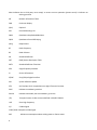

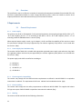


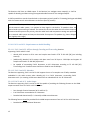

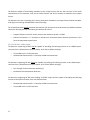
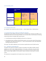

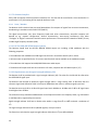
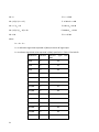
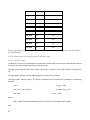


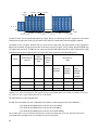
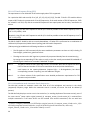

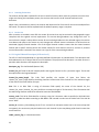
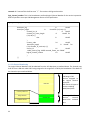


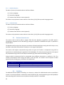
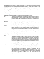
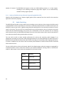


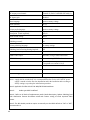
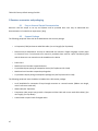
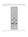


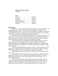


![UFM-30CTL Operation manual[PDF:4.1MB] - FOR](http://vs1.manualzilla.com/store/data/005676883_1-d2048345a5eb1a6d8c39e09dd604009b-150x150.png)