1
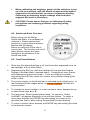
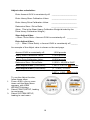
Self-Weighing Truck and Trailer Scales™ QuickLoad™ On-Board Scale Calibration and Operations Manual PN: 901-0124-000 R8 Table of Contents I. QUICKLOAD TRUCK SCALE SYSTEM OVERVIEW ...............5 I.A. Air suspension: basic instructions ......................................5 I.B. Non-air suspension: basic instructions ..............................5 I.B. QuickLoad Scale Overview .................................................6 II. CALIBRATION ..........................................................................7 II.A. Preliminary Considerations ................................................7 II.A.1. 5th Wheel Location, for Calculated Steer ...................8 II.A.2. Air or Non-Air Suspension Steer Axle ........................9 II.A.3 Lift axle considerations ................................................9 II.B. Calibrating Tractor Scale Overview ...................................9 II.B.1 Fast and easy calibration with drop-and-hook trailer .10 II.C. Calibrating Direct-Connect Trailers ..................................11 II.C.1 Easy calibration with direct-connect trailer ................11 II.D. Manual Calibration Procedure .........................................11 II.D.1. Calibrating Empty Weights .......................................12 II.D.2. Calibrating Heavy Weights .......................................14 II.E. Calibration by Direct Entry of RATIO and OFFSET .........15 II.F. Adjusting the Calibration ..................................................15 III. OPERATIONS ........................................................................17 IV. FUNCTIONAL OPERATIONS ...............................................18 IV.A. Weight Displays ..............................................................18 IV.B. How-To-Weigh instructions.............................................19 IV.C. Creating a PIN ................................................................19 IV.D. Alarm Function ...............................................................20 IV.D.1. Alarm Function Programming Procedure ................20 IV.D.1.a. Turning the Alarm Feature On or Off ...................20 IV.D.1.b. Alarm Weights ......................................................20 IV.D.2. Using Alarm 2 For Steer Axle Underweight ............21 2 IV.D.3. Delaying Alarm Activation and Deactivation ...........21 IV.D.4. Changing alarm polarity ..........................................21 IV.E. Languages ......................................................................22 IV.F. Display Backlight and Set-Up .........................................22 IV.G. Filtering or Smoothing Rapid Weight Changes ..............22 IV.H. Models 5826, 5827 Split Axles (DRV1/DRV2) ...............23 IV.I. Large Character Display ..................................................23 VI. MENU OPERATIONS AND DEFINITIONS ...........................25 WEIGHTS DISPLAYS ..............................................................25 MAIN MENU .............................................................................25 WEIGHTS .................................................................................25 ALARMS ...................................................................................25 SETUP, DIAGOSTICS MENU ..................................................25 SYSTEM SETUP MENU ..........................................................25 CALIBRATION ..........................................................................25 SYS CONFIG ............................................................................25 SET PIN # .................................................................................25 SYS CONFIG MENU ................................................................25 DISPLY SETUP ........................................................................25 MODEL NUMBER ....................................................................25 DISPLY SETUP MENU ............................................................26 WEIGHT SETUP MENU ...........................................................26 LBS / KGS ................................................................................26 2 OR 3 LINES ...........................................................................26 DRIVE 1 % ................................................................................26 SHOW / HIDE ...........................................................................26 MORE OPTIONS ......................................................................26 BACKLIGHT .............................................................................26 BRIGHTNESS ..........................................................................26 TRL FRT/REAR ........................................................................26 3 FIRST DISPLY..........................................................................26 MODEL NUMBER ....................................................................27 SHOW / HIDE MENU ...............................................................27 SHOW GVW .............................................................................27 SHOW STEER..........................................................................27 SHOW HELP ............................................................................27 DIAGNOSTICS MENU .............................................................27 SYSTM STATUS ......................................................................27 DIAGNOSTICS: ALARM WEIGHTS MENU ............................27 ALRM WEIGHTS ......................................................................27 TEST ALARM ...........................................................................27 DIAGNOSTICS: SENSORS MENU.........................................27 A/D READINGS ........................................................................28 CALIB DATA .............................................................................28 VII. SYSTEM TROUBLE SHOOTING .........................................28 VII.A. INCORRECT WEIGHT READINGS ..............................29 VII.B. SUSPENSION TROUBLESHOOTING ..........................29 VII.B.1. Ride Height .............................................................30 VII.B.2. Linkage ...................................................................30 VII.B.3. Height Control Valve ..............................................30 VIII. MAINTENANCE ...................................................................30 IX. CUSTOMER SUPPORT.........................................................30 X. Index of Application Notes ...................................................31 XI. Limited Warranty ..................................................................32 XI.A. Procedure for Warranty Claims ......................................33 Appendix: Kit Configuration Sensor Assignment ..................34 Installation data ...........................................................................37 4 I. QUICKLOAD TRUCK SCALE SYSTEM OVERVIEW The QuickLoad™ Scale converts straight truck or tractor and trailer suspension loads to an accurate on-ground weight. Suspensions may be either air or spring. Once calibrated correctly, as described in this manual, the scale will display accurate weights for any load. The scale will display the actual on-ground weight of each air suspension axle group to within 300 pounds (140 kgs). For air suspensions, an axle group is defined by the Height Control Valves (HCV), or leveling valves, on the air suspension. For instance, a tandem drive axle suspension typically has only one HCV, so the two drive axles are referred to as a single axle group and the weight displayed will be for the total tandem weight. For non-air suspensions whose load is measured by a load cell or deflection sensor, an axle group is similarly defined as the set of axles supporting that suspension. The scale will display the actual on-ground weight of each such suspension to within ±2% of its maximum load. The QuickLoad scale display can show up to four axle groups on one straight truck or tractor/trailer combination. Once the QuickLoad is calibrated for weight, it is not necessary to recalibrate unless the suspension characteristics change. For details, see “Troubleshooting”. I.A. Air suspension: basic instructions Calibrate the scale system with the tractor and trailer brakes released, to release suspension binding. Chock the wheels to prevent rolling. Calibrating or observing weight readings with the brakes engaged will result in inaccuracy. For best accuracy, calibrate and weigh on a level surface, with the vehicle adequately chocked to prevent rolling. Air-Weigh recommends that the suspension of a vehicle equipped with air-suspension dump valves be momentarily exhausted and re-inflated before calibrating or weighing. 5-10 seconds of air dump is normally sufficient. This will improve repeatability and accuracy. I.B. Non-air suspension: basic instructions After installing a deflection sensor, operate the vehicle for at least one week before calibrating that axle group, to ensure that the installation settles. (Waiting a week without operating the vehicle will not settle the installation.) 5 When calibrating and weighing, gently roll the vehicle to a stop on a flat level surface, with the wheels straight and the brakes released for the last few feet, to release suspension binding. Calibrating or observing weight readings with the brakes engaged will result in inaccuracy. CAUTION! Please ensure that you are following all safety precautions and company guidelines regarding rolling conditions. I.B. QuickLoad Scale Overview Before using your Air-Weigh QuickLoad Scale, it is necessary to calibrate it. Before starting that process it’s a good idea to become familiar with the display. Below is a definition of the use of each button. The function and use of these buttons remain the same throughout all operations of the QuickLoad scale. I.B. Front Panel Buttons 1. When the QuickLoad backlight is off, the first button depressed turns on the backlight, with no other effect. 2. Depressing the ESC key (with the backlight lit) changes the Weights Display to the Main Menu, depicted above. It changes all other menus and displays to the previous screen. If you are entering a number, depressing the ESC key clears the numeric entry without changing the scale’s value. 3. The cursor location on the QuickLoad is indicated by the blinking line. In the QuickLoad Scale images below, an orange highlight indicates the cursor location. 4. To change the cursor location, or to set a numeric value, depress the up or down arrow keys ▲ or ▼. 5. The instruction “Select [some menu item],” for instance, “Select ALARMS,” will appear frequently in the text that follows. To select a menu item, depress the ENTER key after setting the cursor to the specified line, that is, after making the specified line start blinking. 6. To enter a numeric value, depress the ENTER key after setting the value to the desired number. 6 II. CALIBRATION There are two methods of calibrating the QuickLoad Scale. The usual method is by entering the EMPTY weights into the scale system when the vehicle is empty, and entering the HEAVY weights into the scale system when the vehicle is fully loaded. It’s recommended to have a full tank of fuel when calibrating the steer and drive axle groups. When selecting this calibration method, you MUST enter empty weights when the vehicle is empty and heavy weights when the vehicle is loaded heavy. Failing to do so will result in inaccurate weight readings. th Alternatively, for those with identical suspensions and 5 wheel locations on several vehicles, it may be more convenient to enter the RATIO and OFFSET calibration data directly, if these are known. Use only one of these methods (the usual method, or alternatively, direct ratio and offset entry) to calibrate the scale. Once calibrated, if a suspension’s weight is always incorrect by the same amount on the empty and heavy weights, it is easy to adjust the scale to correct it by using the ADJUST function. Visit our YouTube channel to view our online installation and calibration videos: http://www.youtube.com/user/AirWeigh II.A. Preliminary Considerations The accuracy of the QuickLoad Scale depends on the accuracy of the certified scale used to calibrate or check-weigh. Ensure that the in-ground scale is reliable, recently certified and in good repair. It is preferable to obtain all weight tickets from the same certified scale. This ensures comparative accuracy. Segmented scales, those that provide individual axle group weights, are preferred. When segmented scales are not available, take extra precaution in calculating weights. For the best calibration results with air suspensions, the truck should be: Parked on level ground Full tank of fuel Tractor brakes released Engine running If possible, deflate the suspension for 5 to 10 seconds, and then re-inflate to factory-specified ride height 7 For the best calibration results with non-air suspensions, the truck should be: Operated under normal conditions for a week or 800 miles, whichever comes first, after installation of the deflection sensor Gently rolled to a stop on a flat level surface with wheels straight Brakes unused for the last few feet Brakes released and wheels straight while weighing CAUTION! Please follow all company safety guidelines during weighing and calibration. Once the QuickLoad Scale is calibrated, it is not necessary to re-calibrate unless the suspension characteristics change. Assigning a PIN number during the system set-up process will protect the calibration procedure from tampering. Normally a PIN number is not assigned until AFTER the scale has been calibrated. See Section IV.C for PIN information. II.A.1. 5th Wheel Location, for Calculated Steer If your truck scale system uses the Air-Weigh "calculated steer weight" method, the steer axle weight is determined by the load on the drive suspension and the position of the 5th wheel. In that case, the 5th wheel must be in the same position to weigh as it was when calibrated. The kit includes 5th wheel decals to remind the driver where the calibration/weighing position is located. In normal operations, a driver will set the 5th wheel in a position that allows a maximum GVW load with 12,000 lbs on the steer axle, 34,000 lbs on the drive axles, and 34,000 lbs on the trailer axles. For calibration and weighing, Air-Weigh recommends setting the 5th wheel to the position where both the steer and drive axle weights can be maximized legally, or where the 5th wheel is used most often. The calculated steer axle weight will only be accurate when you weigh with the 5th wheel in the same location as it was when the scale was calibrated. The 5th wheel location affects the accuracy only of calculated steer axle weights. It will not affect either the drive axle weights or sensor-based steer axle weights. Once you have positioned the 5th wheel in the notch that is used most often, apply these decals when you are about to calibrate the Air-Weigh 8 truck scale. Be sure the surface is clean and free of any grease, so the decals will stick permanently. One decal should be on the 5th wheel slider assembly and the other should be on the frame mounting, with the points of the triangles together when calibrating and weighing. How is the leaf spring steer axle weighed? A percentage of weight from the drive axles is transferred to the steer axle. As long as the 5th wheel is positioned in the same notch as when the scale was calibrated, the distance between the 5th wheel and steer axle does not change. Therefore, the ratio of weight transfer does not change. II.A.2. Air or Non-Air Suspension Steer Axle Truck suspensions with a sensor on the steer axle do not use the “calculated steer weight” method, and the steer axle weight will be accurate regardless of the 5th wheel location. II.A.3 Lift axle considerations If your software configuration is 5833 through 5836 or 5838, refer to Product Application Note Calibrating the Lift Axle, Air-Weigh P/N 9010117-000 . All other users should always calibrate with the lift axle up. With the lift axle up, weight readings of all calibrated axle groups, as well as GVW and Net readings, will all be accurate. With the lift axle down, weight readings of all calibrated axle groups will still be accurate. However the GVW and the Net will be inaccurate with the lift axle down for all software configurations except 5833 through 5836 and 5838. II.B. Calibrating Tractor Scale Overview For Manual Calibration, the EMPTY and HEAVY axle weights must be entered by the user. When calibrating using this method, the EMPTY weights must be entered while the vehicle is empty, and the HEAVY weights must be entered while the vehicle is fully loaded. Failure to calibrate scales when vehicle is actually empty and when it has a true heavy load will result in inaccurate weights. Air-Weigh recommends that both empty and full weights be taken on the same reliable, certified scale, preferably a segmented scale that will provide axle weights. The order of calibration is not important; however, both EMPTY and HEAVY weights must be properly entered before the weight display is accurate. Once the calibration procedure is properly completed one time, the EMPTY or HEAVY weights can be updated or re-calibrated individually. 9 II.B.1 Fast and easy calibration with drop-and-hook trailer (This section is only for tractors with drop-and-hook trailers. For directconnect trailers, see II.C Calibrating Direct-Connect Trailers, on the next page.) Here’s a fast and easy way to calibrate a tractor scale. With a fully loaded trailer, go to a reliable, certified scale and weigh the steer axle and the drive axles separately. Move the vehicle to a level spot close by where you can coast to a stop without the brakes and not roll. Briefly exhaust the air suspension for 5 or 10-seconds, and then re-inflate the suspension to factory ride-height. Enter your heavy axle weights into the Air-Weigh scale according to the calibration procedure. Now, drop the trailer in a convenient spot and return the bobtail tractor to the scale to re-weigh the steer and drive axles. Return to your level parking spot, no brakes, re-inflate the suspension, and then enter the empty axle weights into the Air-Weigh scale. Once you’ve properly entered both heavy and empty axle weights, the scale will display the actual on-the-ground weight. Double check the loaded weights when you’ve hooked up the trailer again. Visit our YouTube channel to view our online installation and calibration videos: http://www.youtube.com/user/AirWeigh 10 II.C. Calibrating Direct-Connect Trailers Model numbers 5840, 5841, 5842, 5843, 5844, 5845, 5850, 5851, 5852, 5853, 5854, 5855, 5856, 5857 and 5860 are “trailer-direct” scale systems. In the typical installation of these configurations, an air line from the suspension on the trailer, or (for models 5840 through 5845) air lines from both trailer suspensions, provide pressure directly to a sensor or sensors from which the scale determines the weight of the towed vehicle(s). As with the steer and drive axle groups, you must calibrate the directconnect trailer axle group(s) before you can get their weight readings. And also as with the tractor axle groups, the EMPTY weights must be entered with the trailer(s) empty, and the HEAVY weights must be entered with the trailer(s) fully loaded, before their calibration is complete. II.C.1 Easy calibration with direct-connect trailer (This section is only for tractors with direct-connect trailers. For drop-andhook trailers, see II.B.1 Fast and easy calibration with drop-and-hook trailer, on the previous page.) Here’s an easy way to calibrate a truck scale with direct-connect trailer(s). With a fully loaded trailer, go to a reliable, certified scale and weigh the steer axle, the drive axles, and the trailer(s) axles separately. Move the vehicle to a level spot close by where you can coast to a stop without the brakes and not roll. Briefly exhaust the air suspension for 5 or 10seconds, and then re-inflate the suspension to factory ride-height. Enter your heavy axle weights into the Air-Weigh scale according to the calibration procedure. Later, with the trailer(s) unloaded, return the truck to the scale to re-weigh the steer, drive and trailer(s) axles. Return to your level parking spot, no brakes, re-inflate the suspension, and then enter the empty axle weights into the Air-Weigh scale. Once you’ve properly entered both heavy and empty axle weights, the scale will display the actual on-the-ground weight. Double check the loaded weights later, with the trailer(s) reloaded. II.D. Manual Calibration Procedure Remember, EMPTY or HEAVY weight calibrations can be entered in any order, but the HEAVY weights must be entered while the trailer is loaded, and the EMPTY weights must be entered while the trailer is EMPTY. Additionally, the scale must have both EMPTY and HEAVY weights entered before calibration is complete and accurate weights are displayed. The following two pages give step-by-step procedures for entering the EMPTY and HEAVY calibrations, respectively. 11 II.D.1. Calibrating Empty Weights 1. 2. 3. 4. 5. 6. 7. 8. Press <ESC> one or more times until the Main Menu appears, with VIEW WEIGHTS blinking. Select SETUP, DIAG, leading to next menu. Select SYSTEM SETUP, leading to next menu. Select CALIBRATION, leading to next menu. Select MANUAL CALIBRATION, leading to next menu. Select EMPTY WEIGHT, leading to next menu. The screen pauses for three seconds with the display, “ENTER EMPTY – VEHICLE MUST BE EMPTY” before proceeding automatically to the next menu. On the PICK AXL menu, select one of the offered axle groups: STR (Steer), DRV (Drive), TRL (if only one trailer) or TRA (Trailer A if there are two trailers, or Full Trailer with two axle groups) and TB (Trailer B). If PIN is needed for access, enter it at this time. (See Section IV.C for PIN setup instructions) 12 9. Using the up/down arrows <>, scroll to the proper empty weight identified from a certified scale ticket, then depress <ENTER>. The screen will briefly show Accepted to indicate its acceptance of the Empty Weight. 10. Press <ESC> to return to the PICK AXL menu and choose another axle for entering its Empty Weight calibration. 11. Note that you must calibrate each axle group in order for the scale to be fully calibrated. Repeat the above steps for the Drive axle group, and, if one or more trailers are attached, for the trailer(s) as well. 13 II.D.2. Calibrating Heavy Weights 1. 2. 3. 4. 5. 6. 7. 8. Press <ESC> one or more times until the Main Menu appears, with VIEW WEIGHTS blinking. Select SETUP, DIAG, leading to next menu. Select SYSTEM SETUP, leading to next menu. Select CALIBRATION, leading to next menu. Select MANUAL CALIBRATION, leading to next menu. Select HEAVY WEIGHT, leading to next menu. The screen pauses for three seconds with the display, “ENTER HEAVY – VEHICLE MUST BE HEAVY” before proceeding automatically to the next menu. On the PICK AXL menu, select one of the offered axle groups: STR (Steer), DRV (Drive), TRL (if only one trailer) or TRA (Trailer A if there are two trailers, or Full Trailer with two axle groups) and TB (Trailer B). If PIN is needed for access, enter it at this time. (See Section IV.C for PIN setup instructions) 14 9. Using the up/down arrows <>, scroll to the proper empty weight identified from a certified scale ticket, then depress <ENTER>. The screen will briefly show Accepted to indicate its acceptance of the Heavy Weight. 10. Press <ESC> to return to the PICK AXL menu and choose another axle for entering its Heavy Weight calibration. 11. Note that you must calibrate each axle group in order for the scale to be fully calibrated. Repeat the above steps for the Drive axle group, and, if one or more trailers are attached, for the trailer(s) as well. II.E. Calibration by Direct Entry of RATIO and OFFSET To use this method, you must first obtain the RATIO and OFFSET values from another QuickLoad Scale on a tractor with identical suspension and 5th wheel position, which already has been correctly calibrated. Then you can directly enter these values into the QuickLoad Scale you wish to calibrate. For further details, refer to Product Application Note Calibration by Direct Entry of RATIO and OFFSET Values, Air-Weigh P/N 903-0115-000. II.F. Adjusting the Calibration After the initial calibration is complete and the truck has been operated in normal conditions, you may find that the weights are consistently off up to 1500 lbs GVW in the same direction. You can use the Adjust function to move the calibrated weights closer to those of a certified ground scale. You can use the Adjust function in any vehicle configuration ( for instance, empty or loaded, brakes on or brakes released). Note that you cannot Adjust GVW directly. If you can weigh the axle groups individually at a certified ground scale, you can Adjust each axle group by the amount of its individual consistent error. Otherwise, use the worksheet on the next page to determine how to Adjust the Steer and Drive axle groups, based on the consistent GVW error. 15 Adjust value calculation: Enter Amount GVW is consistently off: ______________________ Enter Heavy Steer Calibration Value: ______________________ Enter Heavy Drive Calibration Value: ______________________ Determine Steer / Drive Ratio: _______________________ (Note: This is the Steer Heavy Calibration Weight divided by the Drive Heavy Calibration Weight.) Steer Adjust Value = Steer / Drive Ratio × Amount GVW is consistently off: _________ Drive Adjust Value = (1 – Steer / Drive Ratio) × Amount GVW is consistently off ______ An example of the Adjust value is shown on the next page. Amount GVW is consistently off: 1,500 pounds Heavy Steer Calibration Value: 21,000 pounds Heavy Drive Calibration Value: 45,000 pounds Determine Steer / Drive Ratio: 21,000 ÷ 45,000 is 0.467 Steer Adjust Value (Calculated): 1,500 × 0.467 is 700 pounds Drive Adjust Value (Calculated): (1 – 0.467) = 0.533. 0.533 × 1,500 = 800 pounds 1. 2. 3. To use the Adjust function, follow these steps. Press <ESC> one or more times until the Main Menu appears, with VIEW WEIGHTS blinking. Select PRINT,SETUP, leading to next menu. Select SYSTEM SETUP, leading to next menu. 16 4. 5. 6. Select ADJUST CALIBRATION, leading to next menu. The screen pauses for three seconds with the display, “ADJUST IF WT ALWAYS OFF BY SAME AMT,” before proceeding automatically to the next menu. On the PICK AXL menu, select one of the offered axle groups: STR (Steer) or DRV (Drive). If PIN is needed for access, enter it at this time. (See Section IV.C for PIN setup instructions) 7. 8. Use the up and down arrows to select the weight adjustment you want to make. Press ENTER once the weight is reached. The screen will display “Accepted” for 2 seconds, then it will return to the previous screen. The weight will show the adjustment and the adjustment itself will again show 0 (zero), as illustrated above. Press <ESC> to return to the PICK AXL menu and choose another axle for entering its Adjust. III. OPERATIONS Once calibrated, your Air-Weigh LoadMaxx Tractor Scale is ready to display weights in 20lb (20kg) increments, and be accurate to within 300lbs (140kgs) of a certified ground scale. Continued accuracy is established by following a few simple rules before taking weight readings: 1. 2. 3. 4. Park the tractor and trailer on a level surface. Release tractor brakes to relieve any binding in the tractor suspension. Chock wheels to ensure vehicle doesn’t roll. If equipped with a dump valve, dump air in tractor suspension for 5 – 10 seconds, then re-inflate to factory-specified ride height. Accurate weight is displayed when numbers stop blinking. It may take a few loads to learn how to weigh accurately, but with a little practice you should be able to weigh within 100 lbs. on a regular basis. With Air-Weigh scales installed on the tractor and trailer suspensions, your entire vehicle becomes the scale. When you want to weigh, remember that you need to weigh the vehicle the same way every time. 17 IV. FUNCTIONAL OPERATIONS IV.A. Weight Displays The Weight Displays show the weights for all axle groups, the GVW (Gross Vehicle Weight), and the NET (Net Vehicle Payload). You can reach the STEER / DRIVE Weight Display by depressing the <ESC> button repeatedly until it appears, or alternatively by selecting VIEW WEIGHTS on the Main Menu and depressing the <ENTER> button. Use the up/down arrows <> to scroll between the various weight displays showing tractor, trailer, and GVW/NET weights. On all Weight Displays, when a weight is changing, it flashes rapidly until it stabilizes. On all Weight Displays, if a particular axle (or GVW or Net) is over the alarm or warning weight, causing an alarm, a bell icon flashes rapidly between the axle name (or GVW or Net) and its weight. On all Weight Displays, pushing Enter stops the alarm unless PIN protection is active. See “Alarm Function,” above, for full details. If no alarm is active, you can zero the NET on the GVW screen by pressing <ENTER> twice while that screen is displayed. The first time, the Net Weight flashes slowly. The second time, it goes to zero. The amount of each addition to, or subtraction from, the GVW will then be added to or subtracted from the Net Weight, allowing you to see how much weight has been loaded or unloaded. 18 IV.B. How-To-Weigh instructions How-To-Weigh instructions are displayed on the tractor scale in rotation with the actual weight screen. To turn off these instructions permanently: 1. 2. 3. 4. 5. 6. 7. 8. Press <ESC> one or more times until the Main Menu appears, with VIEW WEIGHTS blinking. Select SETUP, DIAG, leading to the next menu. Select SYSTEM SETUP, leading to the next menu. Select SYS CONFIG, leading to the next menu. Select DISPLY SETUP, leading to the next menu. Select SHOW / HIDE, leading to the next menu. Select SHOW HELP, leading to the next menu. Select HIDE HELP to turn off the How-To-Weigh instructions. Press <ESC> repeatedly to return to the main menu. Note: You can turn off the How-To-Weigh instructions temporarily, until the next time you turn the truck off and on, by pushing either of the up/down arrows <> when the instructions are visible. IV.C. Creating a PIN When the trailer scale PIN is set to 0, the operator will not need to enter a PIN to access the PROGRAM menu functions. Setting a PIN into the QuickLoad Scale will eliminate tampering with that scale’s CALIBRATION, SCALE TYPE, and PIN settings. After calibration, fleets with both tractor and trailer scales should develop a fleet PIN policy to protect the calibration settings from tampering. To set a PIN: 1. 2. 3. 4. Select SETUP, DIAG, leading to the next menu. Select SYSTEM SETUP, leading to the next menu. Select SYS CONFIG, leading to the next menu. Select SET PIN #, leading to the next menu. If PIN is needed for access, enter it at this time. (See Section IV.C for PIN setup instructions) 19 5. Using the up/down arrows <> scroll to the desired PIN, then depress <ENTER>. Press <ESC> repeatedly to return to main menu. The new PIN is now entered into the scale. To change the PIN later, repeat these steps and change the setting. Setting the PIN to zero will reset the scale’s PIN to its original status of No PIN Needed. Note that once you gain PIN access by entering the PIN correctly, you will retain that access until the scale has a power cycle. IV.D. Alarm Function The Air-Weigh QuickLoad Scale has two 12V-24V alarms. Alarms will activate when a programmed warning weight or alarm weight limit is reached. (Warning weight output is pulsing voltage, while alarm weight output is continuous voltage.) The limits activating this feature are set by the user. Note that you must turn the alarm feature ON for alarm functions to operate. See section IV.D.1.a, below, for details. To deactivate and reset an active warning or alarm weight alarm, simply press the Enter button <ENTER> once while one of the weight displays for tractor, trailer or GVW/NET screen is displayed on the scale display screen. If the scale is not PIN-protected, this will stop the alarm circuit. Once the displayed weight readings fall below the programmed alarm settings, the alarm function resets. The alarm feature is now ready for the next load. Note that all alarm functions, except for the alarm diagnostic test, are PINprotected. IV.D.1. Alarm Function Programming Procedure IV.D.1.a. Turning the Alarm Feature On or Off 1. Press <ESC> one or more times until the Main Menu appears, with VIEW WEIGHTS blinking. 2. Select ALARMS, leading to the next menu. If PIN is needed for access, enter it at this time. (See Section IV.C for PIN setup instructions) 3. The bottom line gives the state of the alarm feature, “(Now ON)” or “(Now OFF).” Select TURN ON/OFF to change this state to its opposite. IV.D.1.b. Alarm Weights 1. Press <ESC> one or more times until the Main Menu appears, with VIEW WEIGHTS blinking. 2. Select ALARMS, leading to the next menu. 20 If PIN is needed for access, enter it at this time. (See Section IV.C for PIN setup instructions) 3. 4. 5. 6. 7. 8. 9. Select SET ALARMS, leading to the next menu. Select ALARM 1, leading to the next menu. Select one of GVW, NET ALM 1, TRCTR ALRMS1, or TRLER ALRMS1, leading to the next menu. Depending on the previous step, select from GVW ALARM and NET ALARM; or from STEER ALARM and DRIVE ALARM; or from TRAILER WARN WT 1 and ALARM WT 1. (If there are two trailers, it will first be necessary to select from TRAILER A and TRAILER B.) Select WARN WT 1 or ALARM WT 1 for the chosen alarm. Using the up/down arrows <> scroll to the desired warning or alarm weight, then depress <ENTER>. Press <ESC> as needed to start setting any additional desired alarms. Press <ESC> repeatedly to return to previous menu or the main menu. Repeat this procedure for ALARM 2 if used. IV.D.2. Using Alarm 2 For Steer Axle Underweight You can change the function of Alarm 2 from its default use as a second overweight alarm. Instead, you can use it to activate when the on-theground weight at the steer axle tires is less than 25% of the on-the-ground weight at the drive axle tires. For details, see Product Application Note QuickLoad, Using Alarm 2 For Steer Axle Underweight, P/N 903-0109-000. Note that this Product Application Note is oriented to straight trucks, not tractor-trailers, so instead of referring to the steer as 25% of the drives, it refers to the steer as 20% of the GVW. However, the function is the same. IV.D.3. Delaying Alarm Activation and Deactivation You can insert a delay between the beginning of an overweight condition and the resulting alarm enunciation, or between the end of an overweight condition and the resulting alarm deactivation. This can keep the alarm from responding to the shocks and vibrations incurred during travel. For details, see Product Application Note Installing and Programming Overweight Alarms, P/N 903-0122-000. IV.D.4. Changing alarm polarity The alarms will default to activating at the line voltage and deactivating at 0 VDC. You can reverse this polarity for each alarm independently. For details, see Product Application Note Installing and Programming Overweight Alarms, P/N 903-0122-000. 21 IV.E. Languages The QuickLoad offers a choice of language display: 1. Press <ESC> one or more times until the Main Menu appears, with VIEW WEIGHTS blinking. 2. Select SETUP, DIAG, leading to the next menu. 3. Select SYSTEM SETUP, leading to the next menu. 4. Select SYS CONFIG, leading to the next menu. 5. Select LANGUAGE, , leading to the next menu. 6. Press the <> buttons to select the desired language, then depress <ENTER>. IV.F. Display Backlight and Set-Up Like other gauges, the scale display is “key-on” powered, so it is always operating. Pressing any key will automatically turn on the display backlight. The display screen will automatically drop into its programmed “sleep mode” with the backlight turned off after one to 30-minutes from the last keystroke operation. The factory-set default time is 5 minutes. To change the amount of time the display is lit 1. Press <ESC> one or more times until the Main Menu appears, with VIEW WEIGHTS blinking. 2. Select SETUP, DIAG, leading to the next menu. 3. Select SYSTEM SETUP, leading to the next menu. 4. Select SYS CONFIG, leading to the next menu. 5. Select DISPLY SETUP, leading to the next menu. 6. Select MORE OPTIONS, leading to the next menu. 7. Select BACKLIGHT, leading to the next menu. 8. Select MINUTES, leading to the next menu. 9. Press the <> buttons to select the desired time period. Press ENTER. This backlight will automatically dim to the “sleep mode” after the selected operation time period. To turn on the backlight, press any button. IV.G. Filtering or Smoothing Rapid Weight Changes You can cause the display to respond more slowly and smoothly to rapidly changing weights by activating the weight filter. For details, see Product Application Note Filtering or Smoothing Rapid Weight Changes, P/N 903-0135-000. 22 IV.H. Models 5826, 5827 Split Axles (DRV1/DRV2) On the Weights Display, model numbers 5826 and 5827 show the drive axle group weight as DRV1 and DRV2. The drives are calibrated as a single axle group and the weight is split according to the DRIVE 1 %. See Product Application Note QuickLoad, Drive 1 and Drive 2 in Models 582223, 5826-27, P/N 903-0112-000. IV.I. Large Character Display The Air-Weigh QuickLoad Scale can display weights on either three lines, with twelve characters per line as shown here on the left, or with larger characters, on two lines, with eight characters per line, as shown here on the right. Only the Weights Displays can appear as large characters on two lines. On this display, axle group names are represented by their first letters: S = STEER D = DRIVE G = Gross Vehicle Weight (GVW) N = Net Payload (NET) T = TRAILER (if semi or full trailer) A = TRAILER A (if two trailers) B = TRAILER B (if two trailers) F = FRONT TRAILER (full trailer) R = REAR TRAILER (full trailer) All other screens always appear as three line displays. To change between two line and three line displays: 1. 2. 3. 4. 5. 6. 7. 8. Press <ESC> one or more times until the Main Menu appears, with VIEW WEIGHTS blinking. Select SETUP, DIAG, leading to the next menu. Select SYSTEM SETUP, leading to the next menu. Select SYS CONFIG, leading to the next menu. Select DISPLY SETUP, leading to the next menu. Select WEIGHT SETUP, leading to the next menu. Select 2 OR 3 LINES, leading to the next menu. At the bottom of the menu the current choice is shown as (Now 2 LINE) or (Now 3 LINE). At this point you can choose between the two line display with larger characters, or the three line display. Press the <> buttons to select the desired display configuration, 2 LINE DISP or 3 LINE DISP, and press <ENTER>. 23 V. QUICK REFERENCE MENU DIRECTORY QuickLoad Scale System SETUP, DIAGN CALIBRATION REQUIRED BEFORE USE SYSTEM SETUP CALIBRATION (Requires PIN#. Each axle suspension must be calibrated separately.) ADJUST CALIB MANUAL CALIB EMPTY WEIGHT HEAVY WEIGHT ENTER RATIO CALIB RATIO CALIB OFFSET SYS CONFIG DISPLAY SETUP WEIGHT SETUP LBS/KGS 2 OR 3 LINES DRIVE 1 %* FILTER FREQ SHOW/HIDE SHOW GVW SHOW STEER SHOW HELP MORE OPTIONS † BACKLIGHT BRIGHTNESS MINUTES TRL FRT/REAR ‡ FIRST DISPLY § MODEL NUMBER (Requires PIN#) LANGUAGE SET PIN # WEIGHTS ALARMS SETUP, DIAG SYSTEM SETUP CALIBRATION SYS CONFIG SET PIN# DIAGNOSTICS WEIGHT Displays first 3 axle weights (Next axle weights if any) <> for GVW/Net Payload Or TRAILER NET PAYLOAD (Models 5830, 5858 and 5861 only) ALARMS SET ALARMS (Requires PIN#.) ALARM 1 (or ALARM 2 if not using STR 20% GVW) GVW, NET ALM1 (or ALM 2) GVW ALARM WARN WT 1 (or 2) ALRM WT 1 NET ALARM WARN WT 1 ALRM WT 1 TRCTR ALRMS1 STEER ALARM WARN WT 1 ALRM WT 1 DRIVE ALARM WARN WT 1 ALRM WT 1 TRLER ALRMS1 WARN WT 1 ALRM WT 1 ALARM CONTRLS STR 20% GVW USE ALARM 2 USE 20% ALRM ALARM LOGIC ALARM 1 (or ALARM 2) ACTIV 12/24V ACTIVE LOW ALARM DELAYS ON 1 OFF 1 ON 2 OFF 2 TURN ON/OFF DIAGNOSTICS SYSTEM STATUS ALARMS ALARM WEIGHTS TEST ALARM SENSORS A/D READINGS CALIB DATA USER DATA<A/D> USER DATA<WEIGHTS> * With models 5822, 5823, 5826 and 5827. † With the models listed in the next footnotes. ‡ With models 5831, 5840, 5841, 5842, 5843, 5844, 5845, 5846 and 5849. § With models 5805, 5806, 5807, 5808, 5814, 5815, 5817, 5818, 5820, 5821, 5824, 5825, 5828, 5829, 5833, 5834, 5835, 5836, 5837, 5838, 5839 and 5864. 24 VI. MENU OPERATIONS AND DEFINITIONS Press the <ESC> button one or more times to reach the Main Menu. Use the <> and <> buttons to scroll to new selections. Refer to the Quick Reference Menu Directory above for the entire menu structure. WEIGHTS DISPLAYS See Section IV.A. MAIN MENU Press <ESC> to enter the Main Menu from the Weights Display. From all other displays, press <ESC> one or more times to reach the Main Menu. WEIGHTS Press <ENTER> to observe the first weights screen, showing at least the STEER and DRIVE axle weights, and possibly the TRLR weight. Press the <> to scroll to additional weight screens for trailer, GVW, and Net Payload weights. ALARMS See Section IV.D. SETUP, DIAGOSTICS MENU Provides access to System Setup menu and Diagnostic menu. SYSTEM SETUP MENU CALIBRATION See Section II. SYS CONFIG See the SYS CONFIG MENU subsection, below. SET PIN # See Section IV.C. SYS CONFIG MENU DISPLY SETUP See the DISPLY SETUP MENU subsection, below. MODEL NUMBER See the MODEL NUMBER MENU subsection, below. 25 DISPLY SETUP MENU WEIGHT SETUP MENU LBS / KGS Changes the weight display and data entry modes to pounds or kilograms. Changing this selection will also automatically convert any calibration values previously entered to the new unit of measure. 2 OR 3 LINES See Section IV.H. DRIVE 1 % With models 5826 and 5827. All other models show LBS/KGS only. See Section IV.G. SHOW / HIDE See the SHOW / HIDE subsection, below. MORE OPTIONS For models 5805, 5806, 5807, 5808, 5814, 5815, 5817, 5818, 5820, 5821, 5824, 5825, 5828, 5829, 5831, 5833, 5834, 5835, 5836, 5837 5838, 5840, 5841, 5842, 5843, 5844 and 5845, allows access to TRL FRT/REAR and/or FIRST DISPLY, as well as to BACKLIGHT. For all other models, only BACKLIGHT is shown. BACKLIGHT Changes the amount of time the display is backlit from last keystroke. Factory default is 5 minutes. Duration can be selected from one to 30 minutes. BRIGHTNESS Allows the selection of a bright or dim backlight, for optimal day or night appearance. TRL FRT/REAR For models 5831, 5840, 5841, 5842, 5843, 5844 and 5845, allows the Weights Display to show two trailer axle groups as either two semi trailers (TRL A and TRL B), or as a full trailer (TRAILER, TRL F, and TRL R). If TRL FRT/REAR is selected, TRAILER gives the sum of TRL F (front) and TRL R (rear). Note that all diagnostic and setup screens refer to TRL F as Trailer A (TRA), and TRL R as Trailer B (TRB). FIRST DISPLY For models 5805, 5806, 5807, 5808, 5814, 5815, 5817, 5818, 5820, 5821, 5824, 5825, 5828, 5829, 5833, 5834, 5835, 5836, 5837 and 5838, the user can select the weights display to appear immediately after power on: the STEER / DRIVE display or the GVW / NET display. 26 MODEL NUMBER Used to change the QuickLoad Truck Scale configuration; for instance, when adding an additional sensor at a later date. Note that otherwise identical configurations will have different model numbers depending on whether or not the sensor operates with air pressure. Consult Air-Weigh Customer Support before changing MODEL NUMBER. SHOW / HIDE MENU SHOW GVW Causes the GVW / Net screen to be visible or not, depending on whether a trailer axle group is configured. SHOW GVW lets the GVW / Net screen be visible even without a trailer. HIDE GVW requires a direct connect trailer suspension to be configured in order to access the GVW / Net screen. SHOW STEER SHOW STEER causes the Steer Axle to be visible on the first Weights Display. HIDE STEER removes the Steer Axle from the first Weights Display, and also prevents access to the GVW / Net screen. SHOW / HIDE STEER is changed automatically with some changes in the Scale Type (see under SYS CONFIG subsection, above). For example, a 5800 model number is identical with a 5803 model number, except that a 5800 has SHOW STEER and a 5803 defaults to HIDE STEER. SHOW HELP See the Section IV.B, How-To-Weigh Instructions, above. DIAGNOSTICS MENU SYSTM STATUS Use this menu to obtain the QuickLoad Scale’s system status, including weight units (Lbs or Kgs), error status, the QuickLoad Scale’s software version numbers and its serial number, and inclinometer diagnostics. Use the up/down arrows <> to scroll between the three SYSTEM STATUS displays, which together show this information. DIAGNOSTICS: ALARM WEIGHTS MENU ALRM WEIGHTS Shows the programmed warning and alarm weights for each axle group, GVW and Net. Values are shown on a different display for each axle group (or GVW or Net). Use the up/down arrows <> to scroll between the axle groups. TEST ALARM Causes both QuickLoad Scale alarms to be actuated for three seconds. DIAGNOSTICS: SENSORS MENU 27 A/D READINGS Shows the sensor reading for each axle group in A/D (electronic) values. For air suspensions, this diagnostic also shows PSI and Bars. Values are shown on a different display for each axle group. Use the up/down arrows <> to scroll between the axle groups. A reading of 409 on an air suspension indicates a sensor fault, sensor cable unplugged, no sensor, etc. For model numbers with averaged dual sensor readings, ‘A/D’ will flash. By pressing the <ENTER> button, you will be able to view the individual AD readings. CALIB DATA Each axle group has values shown on three different displays. The first two are considered User Data, while the third is considered System Data. Use the up/down arrows <> to scroll between the different displays and axle groups. The first display per axle group shows the Empty and Heavy A/D values at the time the user entered Empty and Heavy weights, respectively (unless calibration was performed by direct ratio and offset entry). The second display per axle group shows the Empty and Heavy Weights that the user entered (unless calibration was performed by direct ratio and offset entry). The third display per axle group shows the Ratio and Offset that either the system calculated after the user entered Empty and Heavy weights, or the Ratio and Offset that the user entered. VII. SYSTEM TROUBLE SHOOTING The Air-Weigh QuickLoad Scale system is extremely self-sufficient. To operate correctly, power and ground are the only tractor electrical connections needed. Ensure all connectors (male/female) make a good connection and at least 9.5 volts is entering the system. When troubleshooting, initially check for power at the connecting plugs. If the system used to power up, but now doesn’t, double-check the circuit being used to power it. If there is no power to the scale, use a voltmeter and test the power and ground circuits, using a bracketing method to isolate where power is lost. Once the break in the power circuit is found, make the proper repairs. All other faults can be identified internally through the DIAGNOSTICS display on the scale display. Press <ESC> one or more times until the Main Menu appears, with VIEW WEIGHTS blinking. Select SETUP, DIAGN, leading to the next menu. Select DIAGNOSTICS, leading to the next menu. Select STATUS, leading to the next menu. 28 The screen should show MODEL 58xx Now Lbs (or Now Kgs). If no errors show on the screen, the QuickLoad is functioning normally. Reference the chart below for all fault code problems and solutions. Troubleshooting Chart Code Def EEPROM Problem Description EEPROM error Solution Memory failure. Send to Air-Weigh for repair. VII.A. INCORRECT WEIGHT READINGS If weights are always off by the same amount, see the subsection ADJUST WEIGHTS in the CALIBRATION section, above. If weights are otherwise incorrect, including 0 (zero) or unstable, ensure that the sensor is connected to the QuickLoad Scale correctly. You may use the A/D readings to observe sensor faults. 1. 2. 3. 4. 5. 6. Press <ESC> one or more times until the Main Menu appears, with VIEW WEIGHTS blinking. Select SETUP, DIAGN, leading to the next menu. Select DIAGNOSTICS, leading to the next menu. Select SENSORS, leading to the next menu. Select A/D READINGS, leading to the STR A/D reading. Press the <> buttons to select the desired axle group A/D reading. A reading of 409 (for an air suspension) or less than 50 (for a non-air suspension) indicates a sensor fault, sensor cable unplugged or severed, no sensor, etc. VII.B. SUSPENSION TROUBLESHOOTING Your Air-Weigh Scale’s accuracy is dependent on your suspensions being in good mechanical repair and in factory-specified adjustment. Once the scale is installed and functioning properly, the degree of accuracy will be affected by the proper operation and setting of the suspension. Three major suspension factors affect the degree of accuracy and repeatability: 1. Proper setting of ride height. 2. Proper setting of a high quality height control valve (HCV). 3. Proper adjustment of the HCV linkage. 29 Follow these guidelines to ensure your scale is as accurate and repeatable as possible. VII.B.1. Ride Height Symptoms: Scale readout accuracy varies from certified weight, by varying amounts. Solution: Proper ride height is the most important factor in ensuring accuracy. Ride height is normally defined as the vertical distance from the center of the axle to the bottom of the frame rail. This varies by vehicle and suspension make, so check the proper manual. Most heights are specified +/- 1/8", so the proper setting is critical. VII.B.2. Linkage Symptoms: Scale accuracy varies from a certified weight, usually consistently lower. Solution: Play in the linkage or bushings will detract from scale accuracy since the proper ride height is not always maintained. VII.B.3. Height Control Valve Symptoms: Scale readout is higher or lower than a certified weight, but consistently by the same amount. Solution: Ensure your HCV has minimum dead-band. This is the play in the valve where the ride height changes without actuating the valve. Quality HCVs that demonstrate less than three degrees of total deadband provide most accurate weight readings. Replace defective valve with either Hadley or Barksdale valves. VIII. MAINTENANCE QuickLoad Scale: The Air-Weigh QuickLoad Scale should be maintenance-free under normal operation. Keep the scale in a protected environment and treat as any electronic component. Gently use a clean, soft cloth, slightly damp with water, to wipe away dust from the display. IX. CUSTOMER SUPPORT If you cannot correct a problem, or you suspect you have a malfunctioning part, please contact Air-Weigh Customer Support at (888) 459-3247, Monday through Friday, 7 AM–5 PM Pacific Time. From outside the US and Canada, please call (541) 343-7884. 30 X. Index of Application Notes The following Application Notes are available from Air-Weigh Customer Support for additional information on these subjects: 903-0071-000 – Collecting and Entering Calibration 903-0073-000 – 5800, Calculating Axle Weights on a Platform Scale 903-0079-000 – Best practices for weighing on Volvo Trucks 903-0109-000 – Application Note, ComLink, Using Alarm 2 For Steer Axle Underweight 903-0112-000 – Application Note, ComLink, Drive 1 and Drive 2 in Models 5822-23, 5826-27 903 -0115-000 – Calibration by Direct Entry of RATIO and OFFSET Values 901-0117-000 – Calibrating the Lift Axle 903-0122-000 – Installing and Programming Overweight Alarms 903-0135-000 – Filtering or Smoothing Rapid Weight Changes 31 XI. Limited Warranty For product failures due to material or manufacturing defects, Air-Weigh will replace or repair all air suspension components for up to 3 years from shipment date to the end-user Air-Weigh customer. These three-year components include: Displays, ComLinks, Air Sensors, Power Cables, Air Sensor Assemblies, Air Sensor Harnesses, and all other associated external components. Air-Weigh assumes no responsibility for administering warranty claims directly with any third party end users. The responsibility of Air-Weigh under this warranty is limited to the repair, replacement, or credit of the defective part or assembly. This warranty does not cover incidental or consequential damage to persons or property caused by use, abuse, misuse, or failure to comply with installation or operating instructions. This limited warranty does not apply to any product that has failed due to accident, abuse, alteration, installation not consistent with printed installation instructions, improper maintenance, improper operation, or as a result of system integration or installation not explicitly approved in writing by Air-Weigh. Air-Weigh and its resellers shall have no responsibility or liability for damages if the purchaser or any other person alters the vehicle incorporating Air-Weigh products. This limited warranty shall not apply to any product that has been repaired or altered by anyone not employed by Air-Weigh or not operated in accordance with the manufacturer’s printed material delivered with this product. Air-Weigh hereby expressly disclaims any and all implied warranties of any type, kind of nature whatsoever, particularly any implied warranty of merchantability or fitness for a particular purpose not expressly stated by Air-Weigh in its printed material delivered with its products. Some states do not allow the exclusion or limitation of incidental or consequential damages. If such laws apply, the limitations or exclusions contained in the terms and conditions of this Warranty may not apply. This warranty gives you specific legal rights and you may also have other rights, which vary state to state. May be covered by U.S. Patent Nos. 5478974, 5780782, 7478001 Foreign Patent Nos. 260494, 677998, 2122766 Copyright © 2004, 2006, 2007, 2010, 2013 by Hi-Tech Transport Electronics, Inc. All rights reserved. Air-Weigh®, ComLink™, QuickLoad™ and Hi-Tech Transport Electronics are trademarks or registered trademarks of Hi-Tech Transport Electronics, Incorporated. Other brand, product, or service names listed in this document are the trademarks or registered trademarks of their respective holders. Information contained in this literature was accurate at time of publication. Product changes may have been made after copyright dates that are not reflected. 32 XI.A. Procedure for Warranty Claims 1. In the event Air-Weigh requests to examine product prior to disposition, OR for repairs or replacements, Air-Weigh requires a Return Material Authorization (RMA) number to be issued before the item is returned. Contact Customer Support Department at (888) 459-3247 for an RMA number. Please reference this RMA number in all correspondence. 2. Claimed items shall be shipped freight pre-paid to: Air-Weigh, Customer Support Department, 1730 Willow Creek Circle, Eugene, Oregon 97402, USA. The Air-Weigh RMA number shall appear on the outside of the return packaging. 3. Air-Weigh shall examine returned material within 30 days after receipt, or sooner if mutually agreed upon. If Air-Weigh determines that the part or assembly was defective in material or workmanship and within the warranty period, Air-Weigh will repair or replace the part or assembly and return freight pre-paid. In the event Air-Weigh determines that the part or assembly cannot be repaired or replaced and is within the warranty period, a credit not to exceed the purchase price will be issued to the AirWeigh customer. 4. Air-Weigh Accounting will process a credit memo and notify the AirWeigh customer by email or fax. The Air-Weigh customer will process a corresponding debit memo and notify Air-Weigh Accounting. 5. If the part or assembly received by Air-Weigh does not meet the requirements of the warranty program set forth above, at the Air-Weigh customer’s request the part or assembly will either be discarded, returned freight collect, or repaired or replaced at the Air-Weigh customer’s expense and returned freight collect. 1730 Willow Creek Circle • Eugene, Oregon 97402-9152 USA P.O.Box 24308 • Eugene, Oregon 97402-0437 USA Telephone (541) 343-7884 • Order Desk (888) 459-3444 Customer Support (888) 459-3247 • FAX (541) 431-3121 Hours of Operation: Mon-Fri, 7am – 5pm, Pacific Time www.Air-Weigh.com 33 Appendix: Kit Configuration Sensor Assignment Number See Kit Part Number for Model Number Sensor Installed on this Suspension HCV = Height Control Valve Sensor Type AP = Air Pressure Sensor QuickLoad Sensor Cable Input Jack DS = Deflection Sensor LC = Load Cell 5800 Drive 5801 Drive, Dual HCV’s AP, AP AP Sensor A & B Sensor A 5803 Drive, Hide Steer AP Sensor A 5805 Drive Steer AP AP Sensor A Sensor B 5806 Drive, Dual HCV’s Steer AP, AP AP Sensor A & B Sensor C 5807 Drive Steer AP DS Sensor A Sensor B 5808 Drive, Dual HCV’s Steer AP, AP DS Sensor A & B Sensor C 5810 Drive, Dual Defl’n Sensors DS, DS Sensor A & B 5814 Drive, Dual Defl’n Sensors Steer DS, DS Sensor A & B DS Sensor C Drive, Dual HCV’s AP, AP Sensor A & B Steer, Dual HCV’s AP, AP Sensor C & D 5816 Drive, Dual HCV’s, Hide Steer AP, AP Sensor A & B 5817 Drive Steer DS DS Sensor A Sensor B 5821 Drive <not used> Steer, Dual HCV’s AP N/A AP, AP Sensor A Sensor B Sensor C & D 5826 Drive Steer AP AP Sensor A Sensor B 5827 Drive, Dual HCV’s Steer AP, AP AP Sensor A & B Sensor C 5828 Drive <not used> Steer, Dual Defl’n Sensors AP N/A Sensor A Sensor B DS, DS Sensor C & D DS, DS Sensor A & B Steer DS Sensor C Lift AP Sensor D 5815 Drive, Dual Defl’n Sensors 5833 34 Number See Kit Part Number for Model Number 5834 5835 Sensor Installed on this Suspension HCV = Height Control Valve Sensor Type AP = Air Pressure Sensor QuickLoad Sensor Cable Input Jack DS = Deflection Sensor LC = Load Cell Drive Steer Lift DS DS AP Sensor A Sensor B Sensor C Drive Steer Lift AP DS AP Sensor A Sensor B Sensor C AP, AP DS AP Sensor A & B Sensor C Sensor D 5836 Drive, Dual HCV’s Steer Lift 5838 Drive Steer Lift AP AP AP Sensor A Sensor B Sensor C 5839 Drive Steer Pusher Lift Tag Lift DS DS AP AP Sensor A Sensor B Sensor C Sensor C Trailer Direct 5840 Drive, Hide Steer Trailer, Trailer – BTrain AP Sensor A AP, AP Sensor B & C Trailer Direct 5841 Drive Trailer, Trailer – BTrain AP Sensor A AP, AP Sensor B & C Trailer Direct 5842 Drive Steer Trailer, Trailer – BTrain AP AP Sensor A Sensor B AP, AP Sensor C & D Trailer Direct 5843 Drive Steer Trailer, Trailer – BTrain AP DS Sensor A Sensor B AP, AP Sensor C & D Trailer Direct 5844 Drive, Dual HCV’s Trailer, Trailer – BTrain AP, AP Sensor A & B AP, AP Sensor C & D Trailer Direct 5845 Drive, Dual HCV’s Trailer, Trailer – BTrain AP, AP Sensor A & B AP, AP Sensor C & D 35 Number See Kit Part Number for Model Number Sensor Installed on this Suspension HCV = Height Control Valve Sensor Type AP = Air Pressure Sensor QuickLoad Sensor Cable Input Jack DS = Deflection Sensor LC = Load Cell Drive LC Sensor A Trailer Direct 5846 Steer DS Sensor B AP, AP Sensor C & D Trailer Direct 5850 Drive, Hide Steer AP Sensor A Trailer AP Sensor B Trailer Direct 5851 Drive AP Sensor A Trailer AP Sensor B Drive AP Sensor A Steer AP Sensor B Trailer AP Sensor C Drive AP Sensor A Steer Trailer DS AP Sensor B Sensor C AP, AP Sensor A & B Trailer Direct 5852 Trailer Direct 5853 Trailer, Trailer – BTrain Trailer Direct 5854 Drive, Dual HCV’s, Hide Steer Trailer AP Sensor C Trailer Direct 5855 Drive, Dual HCV’s Trailer AP, AP AP Sensor A & B Sensor C Trailer Direct 5856 Drive, Dual HCV’s Steer Trailer AP, AP AP AP Sensor A & B Sensor C Sensor D Trailer Direct 5857 Drive, Dual HCV’s Steer Trailer AP, AP DS AP Sensor A & B Sensor C Sensor D Trailer Direct 5860 Drive, Dual HCV’s Trailer, Dual HCV’s AP, AP AP, AP Sensor A & B Sensor C & D Drive AP Sensor A Steer Pusher Lift Tag Lift DS AP AP Sensor B Sensor C Sensor C AP, AP Sensor A & B DS Sensor C 5864 5878 No FSK Drive, Dual HCV’s Steer 36 Installation data See Diagnostics Menu sections, pages 24 – 25, to find the following. QuickLoad Scale serial number DIAGNOSTICS / SYSTM STATUS /▼ _________________________ QuickLoad Scale software version DIAGNOSTICS / SYSTM STATUS /▼ _________________________ Steer axle calibration empty A/D DIAGNOSTICS / SENSORS / CALIB _________________________ Steer axle calibration heavy A/D DIAGNOSTICS / SENSORS / CALIB _________________________ Steer axle calibration empty weight DIAG / SENSORS / CALIB /▼ _________________________ Steer axle calibration heavy weight DIAG / SENSORS / CALIB /▼ _________________________ Steer axle calibration ratio DIAG / SENSORS / CALIB /▼▼ _________________________ Steer axle calibration offset DIAG / SENSORS / CALIB /▼▼ _________________________ Drive axle calibration empty A/D DIAG / SENSORS / CAL /▼▼▼ _________________________ Drive axle calibration heavy A/D DIAG / SENSORS / CAL /▼▼▼ _________________________ Drive axle calibration empty weight DIAG / SENSORS / CAL /▼▼▼ ▼ _________________________ Drive axle calibration heavy weight DIAG / SENSORS / CAL /▼▼▼ ▼ _________________________ Drive axle calibration ratio DIAG / SENSORS / CAL /▼▼▼ ▼▼ _________________________ Drive axle calibration offset DIAG / SENSORS / CAL /▼▼▼ ▼▼ _________________________ Steer axle warning 1 weight DIAGNOSTICS / ALARMS / WEIGHTS _________________________ Steer axle alarm 1 weight DIAGNOSTICS / ALARMS / WEIGHTS _________________________ Drive axle warning 1 weight DIAG / ALARMS / WEIGHTS /▼ _________________________ 37 Drive axle alarm 1 weight DIAG / ALARMS / WEIGHTS /▼ _________________________ GVW warning 1 weight DIAG / ALARMS / WEIGHTS /▼▼▼ _________________________ GVW alarm 1 weight DIAG / ALARMS / WEIGHTS /▼▼▼ _________________________ Net warning 1 weight DIAG / ALARMS / WTS /▼▼▼ ▼ _________________________ Net alarm 1 weight DIAG / ALARMS / WTS /▼▼▼ ▼ _________________________ Steer axle warning 2 weight DIAG / ALARMS / WTS /▼▼▼ ▼▼ _________________________ Steer axle alarm 2 weight DIAG / ALARMS / WTS /▼▼▼ ▼▼ _________________________ Drive axle warning 2 weight DIAG / ALARMS / WTS /▼▼▼ ▼▼▼ _________________________ Drive axle alarm 2 weight DIAG / ALARMS / WTS /▼▼▼ ▼▼▼ _________________________ GVW alarm 2 weight DIAG / A’S / WTS /▼▼▼ ▼▼▼ ▼ _________________________ GVW warning 2 weight DIAG / A’S / WTS /▼▼▼ ▼▼▼ ▼ _________________________ Net alarm 2 weight DIAG / A’S / WTS /▼▼▼ ▼▼▼ ▼▼ _________________________ Net warning 2 weight DIAG / A’S / WTS /▼▼▼ ▼▼▼ ▼▼ _________________________ 38 Notes 39 1730 Willow Creek Circle • Eugene, Oregon 97402-9152 USA P.O.Box 24308 • Eugene, Oregon 97402-0437 USA Telephone (541) 343-7884 • Order Desk (888) 459-3444 Customer Support (888) 459-3247 • FAX (541) 431-3121 Hours of Operation: Mon-Fri, 7am – 5pm, Pacific Time www.Air-Weigh.com 40