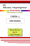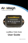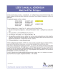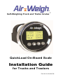
1
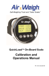
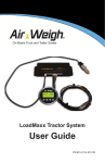
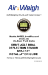
Self-Weighing Truck and Trailer Scales ™ QuickLoad On-Board Scale Installation Guide for Trucks and Tractors PN: 901-0123-000 R6 TABLE OF CONTENTS I. SCALE OVERVIEW .................................................................... 4 1. QuickLoad Tractor Scale Overview ................................ 5 2. Installation Overview for QuickLoad Scale System ......... 7 A. Overview for Electronic Components Installation ........ 7 B. Overview for Air Pressure Sensor(s) Installation ......... 7 C. Overview for Deflection Sensor(s) Installation ............ 8 II. QUICKLOAD PARTS PER VEHICLE TYPE ............................... 9 III. TOOLS REQUIRED (CUSTOMER SUPPLIED) ......................... 11 1. Tools for Air Pressure Sensor(s) installation ................ 11 2. Tools for Deflection Sensor Installation ........................ 11 IV. INSTALLING THE QUICKLOAD SCALE .................................. 12 1. Installing the QuickLoad Display .................................. 12 A. Preparing the QuickLoad Display for Installation ....... 12 B. Mounting the QuickLoad Display .............................. 12 2. Connecting the QuickLoad Wiring Harness .................. 13 A. Connecting the QuickLoad to Power ........................ 13 B. Connecting the QuickLoad to Sensors and Alarms ... 14 B. Secure Cables and Reassemble the Dash ............... 14 3. V. QuickLoad Connection Diagrams ................................ 15 INSTALLING AIR SUSPENSION SENSOR(S) ......................... 19 1. Air Line Installation for each leveling valve................... 19 A. Route Air Line from Air Suspension ......................... 19 B. Routing Air line for Dedicated Tractor / Trailer Scale 20 2. Installing Sensor(s) ..................................................... 23 A. Installing Air Pressure Sensor (s) ............................. 23 B. Installing Scales with a Steer Axle Deflection Sensor 25 C. Parts and Sensor Configuration Tables .................... 26 2 Setting the QuickLoad’s Sensor Configuration ............. 31 3. VI. A. Front Panel Buttons................................................. 31 B. Entering the Sensor Configuration ........................... 32 FOR FURTHER INFORMATION ............................................... 33 LIMITED WARRANTY ...................................................................... 34 3 I. SCALE OVERVIEW The Air-Weigh® QuickLoad Scale™ for trucks and tractors with AP (Air Pressure) drive suspension includes a dashboardmounted a QuickLoad display, power harness, sensor cable(s), and sensor(s) with mounting hardware. This Installation Guide (p/n: 901-0123-000) gives instructions for scale installations on vehicles having air or spring drive suspensions, possibly in combination with air or spring steer suspensions. It also includes dedicated tractor and trailer configurations. See Table 7. Kit Configuration Sensor Assignment for more detail on the various vehicle configurations. Follow Air-Weigh’s installation procedures exactly for the most accurate weighing. The User Guide (p/n: 901-0124-000), included also with the scale, provides the complete scale calibration and operation procedures. These procedures include, among others, the steps for setting up the scale for your specific sensor configuration. Table 1. Specifications QuickLoad Scale Weigh Reading Accuracy Diameter: 2.43 inches (61.7 mm) Height: 3.10 inches (78.7 mm) Weight: 4.7 oz. (133 g) Operating Temperature Range: -4 to 158F (-20 to 70C) Input voltage: 9.5V DC to 32V DC Alarm Output Circuit Limit: 1.0 amps Axle with Air Sensor: ±300 lbs (140 kgs) per axle group Axle with Deflection Sensor: ±2% maximum axle group weight 4 1. QuickLoad Tractor Scale Overview The QuickLoad scale converts tractor and trailer suspension loads to an accurate on-ground weight by comparing empty and loaded axle group weights with empty and loaded sensor output. Once calibrated, the scale displays accurate weights for any air suspension load. The scale displays the actual on-ground weight of each axle group to within 300 pounds (140 kilograms) for air suspensions, or ±2% of maximum axle group weight for spring suspensions. An axle group is defined by the Height Control Valve(s) (HCV), or leveling valve(s), on the air suspension, or as the set of axles supporting a spring suspension. For instance, a tandem drive axle suspension typically has only one HCV. The two drive axles make up a single group and the displayed weight will be for the total tandem weight. The QuickLoad scale can display up to four axle groups on one tractor/trailer combination. Once the QuickLoad is calibrated for weight, it is not necessary to recalibrate unless the suspension characteristics change. Following installation, you must calibrate the scale before you can use it to determine axle group and vehicle weight. For instructions on calibration, please consult p/n 901-0124-000, QuickLoad Calibration and Operations Manual. 5 Figure 1. Air Pressure Drive Sensor Hookup Figure 2. Deflection Sensor Drive Sensor Hookup Legend: 6 2. Installation Overview for QuickLoad Scale System This guide will give all necessary details of the following steps for installing the QuickLoad Scale System. Air lines and cables to the sensor, and any other Air-Weigh wiring, must be separated by a minimum of 12 inches, or properly shielded, from exhaust piping. Ensure that each sensor’s electrical cable is connected to the correct QuickLoad port. For a list of the correct port for each sensor, see Table 7, page 22. A. Overview for Electronic Components Installation Cut hole in dash for display; mount QuickLoad to dash. – OR – B. Mount QuickLoad in pod on top of dash, using the optional pod mounting kit, P/N: 1225. Overview for Air Pressure Sensor(s) Installation For air suspension scales with air bag(s) on the drive suspension, install air pressure sensor(s) under dash. Route air line(s) from drive suspension to sensor(s) installed under dash. For scales which calculate the weight at the steer axle from the drive axle suspension (configurations 5800, 5801, 5841, 5845, 5851, 5855, 5860), no steer axle sensor is needed. 7 C. For scales where the steer axle weight is intentionally not displayed (configurations 5803, 5809, 5810, 5816, 5840, 5844, 5850, 5854), no steer axle sensor is needed. For scales with a steer axle with air suspension (configurations 5805, 5806, 5815, 5821, 5826, 5827, 5838, 5842, 5847, 5852, 5856), route air line(s) from steer axle suspension to sensor(s) installed under dash. For scales which determine the weight at the lift axle (configurations 5833 – 5836, 5838, 5839 and 5864), refer to p/n 901-0117-000, Application Note, LoadMaxx, Installing and Calibrating the Lift Axle, for lift axle sensor installation instructions. For Dedicated Tractor/Trailer Scales (configurations 5840 – 5857 except 5849), route trailer suspension air line(s) to sensor(s) installed under dash. Overview for Deflection Sensor(s) Installation For scales that include steer axle deflection sensors (configurations 5807, 5808, 5814, 5817, 5820, 5822, 5823, 5825, 5828, 5829, 5831, 5833, 5834, 5835, 5836, 5839, 5843, 5846, 5853, 5857 and 5864), refer to p/n 901-0059-000, Steer Axle Deflection Sensor Kit Installation Guide, for installation instructions. For scales that include dual drive axle deflection sensors on Hendrickson™ HaulMaxx or HN 462/463 suspensions (configurations 5810, 5814, 5818, 5824, 5829 or 5833), refer to p/n 901-0092-000, Drive Axle Dual Deflection Sensor Installation Guide. For scales that include a single drive axle deflection sensor (configurations 5807, 5708, 5817, 5833 – 5836, 5839, 5843, 5853), contact Air-Weigh. 8 II. QUICKLOAD PARTS PER VEHICLE TYPE The most popular QuickLoad parts are shown in Table 2, below. See Table 6 for a comprehensive listing of all QuickLoad parts. The Air Line and Disconnect kits in Table 2 are optional. They are needed only if the vehicle does not already have those air lines and disconnects, bringing air pressure from the air suspension to behind the dash, already in place. Table 2: QuickLoad Part Numbers Part Number Description 1350 QuickLoad Display Kit which includes the display, mounting hardware, power cable, and user manual. 1360 QuickLoad Air Sensor Kit which includes a single air pressure sensor, push-in fittings, and a 3' cable. 1361 QuickLoad Air Sensor Kit which includes dual air pressure sensors, push-in fittings, two 3' cables and a Y Cable. For 3-sensor and 4-sensor systems only. 1380 QuickLoad Alarm Kit. 1390 Deflection Sensor Kit which includes 15’ sensor cable, mounting brackets, and installation manual. 010-0023-000 Air Line Kit (optional) 010-0028-002 Trailer Disconnect Kit (optional) 010-0029-002 Two Trailer Disconnect Kit (optional) 9 QuickLoad parts per vehicle type, for the most popular software configurations, are shown in Table 3, following. See Table 7 for a comprehensive listing of QuickLoad parts for all vehicle types. All configurations require P/N 1350, QuickLoad Display Kit, which is not otherwise shown in the following table. Table 3: QuickLoad Parts for the Most Popular Vehicle Configurations Vehicle Description Drive Suspension Tractor Air-Ride Single HCV Tractor Air-Ride Dual HCV Truck Tractor Air-Ride Single HCV Air-Ride Single HCV Truck Air-Ride Single HCV Dedicated Tractor Trailer Air-Ride Single HCV Dedicated Tractor Trailer Air-Ride Single HCV Steer Leaf Spring, Calculated to 1% Leaf Spring, Calculated to 1% Leaf Spring, Not Displayed Air-Ride Single HCV Leaf Spring, Deflection Sensor Leaf Spring, Not Displayed Leaf Spring, Calculated to 1% 10 Trailer Suspension Parts Needed Software Config Not Included 1 ea. 1360 5800 Not Included 2 ea. 1360 5801 Not Included 1 ea. 1360 5803 Not Included 2 ea. 1360 5805 Not Included 1 ea. 1360 1 ea. 1390 5807 Air-Ride Single HCV 2 ea. 1360 5850 Air-Ride Single HCV 2 ea. 1360 5851 III. TOOLS REQUIRED (CUSTOMER SUPPLIED) 1. Tools for Air Pressure Sensor(s) installation Screwdrivers – flathead and/or Philips Assorted wrenches Drill 2 1/8” hole saw Optional ¾” hole saw for running air line to dash Safety glasses Wire cutter Crimper Teflon™ pipe thread tape 2. Tools for Deflection Sensor Installation Sander with 40-grit medium Chalk or permanent marker Flat blade screwdriver 9/16-inch combination wrench Torque wrench, 20 – 80 ft-lb 9/16-inch deep well socket with ⅜-inch socket handle ½-inch to ⅜-inch socket adapter Optional: Deflection Sensor Field Test Set The Deflection Sensor Install Field Test Set, p/n 1000, can measure raw deflection sensor readings without the sensor’s connection to the QuickLoad Scale. For installation of the steer axle deflection sensor, refer to p/n 901-0059-000, Steer Axle Deflection Sensor Kit Installation Guide, which is included in kits 1390 and 1391. 11 For installation of the Hendrickson Walking Beam drive axle deflection sensors, refer to p/n 901-0092000, Steer Axle Deflection Sensor Kit Installation Guide, which is included in kit 1392. IV. INSTALLING THE QUICKLOAD SCALE The installation of an Air-Weigh QuickLoad Scale on a vehicle includes mounting two major classes of components: Electronics components: QuickLoad display and power interface cable Sensor(s) and sensor cable(s) 1. Installing the QuickLoad Display A. Preparing the QuickLoad Display for Installation Numbers called out in refer to Figure 3 unless otherwise stated. 1. Select a location for the display (1) on the dash panel (5) with at least 3-inch clearance behind the dash panel for the unit and its connections. A higher dash position provides better visibility. 2. Cut a 2⅛-inch hole (2) in the dash at that location. 3. Remove the hex nuts (4) from the studs (6) on the back of the display (1) to release the mounting bracket (3). B. Mounting the QuickLoad Display 1. Position the display (1) in the hole (2) so that it appears level on the dash, as shown in Figure 3. 2. Reinstall the mounting bracket (3) on the back of the display and secure with two nuts (4) on the display studs (6). Tighten the nuts and secure the display to the dash using 6 ft-lbs. of torque. Do not over tighten the mounting bracket nuts. 12 2 3 1 4 6 5 AW0099-1006 Figure 3. Installing the Display 2. Connecting the QuickLoad Wiring Harness A. Connecting the QuickLoad to Power The QuickLoad power wiring harness, p/n 012-0600-008, connects the QuickLoad scale to the vehicle’s power and ground circuits. Consult Table 4. Table 4. Wiring Harness Hookup Power and Ground Table White wire Vehicle chassis ground Blue/Black wire with in-line fuse 12VDC or 24VDC ignition hot power 1. Connect the white wire to chassis ground. 2. Connect blue/black wire with inline fuse to the positive (+) or “hot” side of the 12 VDC or 24 VDC ignition power source. DO NOT connect directly to battery. 13 B. Connecting the QuickLoad to Sensors and Alarms 1. Connect the 4-pin sensor cable(s) to the QuickLoad Sensor Inputs A, B, or C/D, as indicated in the Sensor Connection figures, pages 15-17. 2. To connect an external alarm using the QuickLoad Alarm Kit (p/n 1380), consult the QuickLoad Alarm Kit Manual, included in the Alarm Kit. a) Connect the 4-pin sensor cable with alarm lead to the QuickLoad Sensor Input specified in the Sensor Connection figures, pages 15-17. b) Connect the sensor cable alarm lead to the end of the alarm cable. c) Connect the alarm (or alarm light) power wire to a 12V/ 24V ignition hot source. 3. Turn on key for system self-test. If system does not successfully complete the self-test, see Troubleshooting Section at the end of this manual. B. Secure Cables and Reassemble the Dash 1. Coil excess wires and harnesses and secure using nylon cable ties. 2. Tie wires and sensor assemblies to other secured harnesses, to prevent damage due to vibration. 3. Reassemble the dash assembly. Ensure all connections are tight. 4. Turn the ignition key ON and perform a final system check. 14 3. QuickLoad Connection Diagrams Please reference Table 7. Kit Configuration Sensor Assignment, for the sensor configuration required for your installation. The following figures give a view of the connectors on the back face of the QuickLoad Scale. They show where the ports for the different configurations mentioned in Table 7 are located. A – Port for sensor and 1st alarm connection PWR – Power connection C/D – Port for single or dual sensor connection B – Port for sensor and 2nd alarm connection Figure 4. QuickLoad sensor and alarm ports A – Port for sensor connection (Optional: 1st alarm connection) PWR – Power connection Figure 5. Connections for single sensor system 15 PWR – Power connection A – Port for sensor connection (Optional: 1st alarm connection) B – Port for sensor connection (Optional: 2nd alarm connection) Figure 6. Connections for a two sensor system PWR – Power connection A – Port for sensor connection (Optional: 1st alarm connection) B – Port for sensor connection (Optional: 2nd alarm connection) C – Port for sensor connection Figure 7. Connections for most three sensor systems (excludes 5821 and 5828) 16 A – Port for sensor connection (Optional: 1st alarm connection) PWR – Power connection C/D – Port for dual sensor connection Figure 8. Connections for configurations 5821 and 5828 PWR – Power connection A – Port for sensor connection (Optional: 1st alarm connection) C/D – Port for two single or one dual sensor connection B – Port for sensor connection (Optional: 2nd alarm connection) Figure 9. Connections for four sensor system 17 The scale will only display accurate weights after it has been completely calibrated to a certified platform scale, by entering empty and loaded axle weights into the Air-Weigh Scale. Enter empty weights only when the vehicle is empty! Enter loaded weights only when the vehicle is loaded! See QuickLoad Calibration and Operations Manual, p/n 901-0124-000, for complete instructions. 18 V. INSTALLING AIR SUSPENSION SENSOR(S) 1. Air Line Installation for each leveling valve A. Route Air Line from Air Suspension Follow the same instructions for air line and sensor installation for both drive and steer air suspensions. The parts in this section’s instructions are listed in Table 5. If an Air Suspension Gauge for the suspension already exists in dash, skip to V.2, Installing Sensor(s). Otherwise, continue with this procedure. 1. Route a ¼-inch air line from the airbag suspension to the dash. Additional Air Line Air Supply Line for Airbag T-fittings Air Line to Sensor Airbag Figure 10. Airbag and Air Line Connections 2. Use a ¼-inch straight street-T at the top of a convenient drive axle suspension air bag to access 19 air pressure. If you choose to connect in the middle of an existing air line between two air bags, thoroughly remove any paint on the air line and wipe clean before cutting the air line. 3. Route the air line along with other air lines and cables into the dash. Loosely connect the air line to the other air lines and cable with cable ties to prevent it from being damaged. Avoid connecting on the air bag’s supply line. B. Routing Air line for Dedicated Tractor / Trailer Scale The parts in this section’s instructions are listed in Table 5. If Trailer Suspension gauge already exists in dash, skip to V.2, Installing Sensor(s). Table 5. Air Line and Disconnect Kit BOMs Bill of Materials for Suspension Air Line Kit, p/n 010-0023-000 PART NUMBER DESCRIPTION QTY 145-4552-001 NYLON TIE, 7", T-50, NYLON, BLK 25 150-4081-000 ¼ NPT STREET TEE, DOT, BRASS 1 150-4083-000 DOT COMPRESSION, ¼ NPT, MALE,BRASS 1 380-0046-000 40' X ¼” SAE J844 DOT TUBING 1 BOM for Trailer-Direct Disconnect Kit, p/n 010-0028-002 145-4552-001 NYLON TIE, 7", T-50, NYLON, BLK 25 150-4081-000 ¼ NPT STREET TEE, DOT, BRASS 1 150-4083-000 DOT COMPRESSION, ¼ NPT, MALE,BRASS 3 20 150-4091-000 FITTING, BRASS, QUICK COUPLER, MALE 1 150-4092-000 FITTING, BRASS, ADAPTER PLUG,FEMALE 1 152-0001-000 BULKHEAD FITTING, 1/4" NPT 2 380-0050-000 100' X ¼” SAE J844 DOT TUBING 1 380-0053-000 AIR HOSE, COILED, 1/4" NPT X 2, 25’ 1 901-0052-000 INSERT, AW5800, TRAILER-DIRECT 1 BOM for Two-Trailer-Direct Disconnect Kit, p/n 010-0029-002 145-4552-001 NYLON TIE, 7", T-50, NYLON, BLK 50 150-4081-000 ¼ NPT STREET TEE, DOT, BRASS 2 150-4083-000 DOT COMPRESSION, ¼ NPT, MALE,BRASS 8 150-4091-000 FITTING, BRASS, QUICK COUPLER, MALE 3 150-4092-000 FITTING, BRASS, ADAPTER PLUG,FEMALE 3 152-0001-000 BULKHEAD FITTING, 1/4" NPT 6 380-0046-000 40' X ¼” SAE J844 DOT TUBING 1 380-0050-000 100' X ¼” SAE J844 DOT TUBING 2 380-0053-000 AIR HOSE, COILED, 1/4" NPT X 2, 25’ 3 901-0065-000 INSERT, AW5800, TWO-TRAILERS-DIRECT 1 1. Remove existing air line connection from one trailer air bag. 2. Install street-T (p/n: 150-4081-000) into air bag. 3. Install fitting (p/n: 150-4083-000) into side of street-T and connect to air line (p/n: 380-0050000). 4. Reinstall original air line and fitting connector to top of street-T. 21 5. Run air line (p/n: 380-0050-000) to front of trailer. Secure with cable ties. 6. Drill hole for trailer bulkhead fitting at a point near where existing airlines attach to trailer. 7. Install bulkhead fitting (p/n: 152-0001-000). 8. Cut air line to length and connect to rear side of bulkhead fitting. Use remaining air line in step 13. 9. Attach female quick-disconnect coupling (p/n: 1504092-000) to face of bulkhead fitting. Female coupling MUST be connected to trailer air line to keep air in suspension system. 10. Connect end of coiled air line (p/n: 380-0053-000) with male quick disconnect coupling to female quick disconnect coupling (p/n: 150-4092-000). See Figure 11. Air Line Female Quick Disconnect Coupler Bulkhead Fitting Male Quick Disconnect Coupler Bulkhead Fitting Jamnut Bulkhead Coiled Air Line AW0099-1003 Figure 11. Installing Bulkhead Connector 11. Attach quick disconnect fitting (p/n: 150-4091-000) to one end of coiled air hose and couple to quick 22 disconnect fitting (p/n: 150-4092-000) on front bulkhead of trailer. See Figure 11. 12. Drill hole in tractor bulkhead near where existing air lines attach to the tractor and install bulkhead fitting (p/n: 152-0001-000). 13. Connect the other end of the coiled air line (p/n: 380-0053-000) to the face of the bulkhead fitting. 14. Install brass fitting (p/n: 150-4083-000) into rear of bulkhead fitting. Run air line (380-0050-000) from brass fitting to under dash, close to QuickLoad mounting location. Secure with wire ties. 15. Connect open end of air line, near QuickLoad, to push-on fitting on end of Air Pressure Sensor. 16. Connect electrical cable from opposite end of air pressure sensor to appropriate port on QuickLoad. See Table 7. Kit Configuration Sensor Assignment to determine the appropriate port for the sensor connector. 2. Installing Sensor(s) Avoid dropping the sensors. Dropping can cause the sensors to fail immediately or shorten their lifespan. A. Installing Air Pressure Sensor (s) There are two methods of installing the sensor connections to the suspension air line(s) under the dash. See Figure 12. Connecting the Air Pressure Sensor 1. Insert a T-fitting into an existing suspension air gauge. 2. Terminate the air line into the nickel plated brass fitting supplied by Air-Weigh. 23 The Air-Weigh kit includes fittings for terminating air lines of either of two diameters, ¼-inch and 5/32-inch. The customer will need to purchase additional fittings to insert a T-fitting into an existing air line. Air-Weigh only supplies the connectors needed for a terminated connection. 1. Connect sensor to fitting and tighten. Using a torque wrench, set torque to approximately 25 ft-lbs. 2. Push end of air line into fitting and ensure connection is firmly secured. While the air line can be removed from the fitting by retracting the O-ring while gently pulling the air line out, repeated removal and replacement will weaken the seal. Air Line Air - Weigh Furnished Fitting Air Pressure Sensor Optional T-fitting (Customer Furnished) AW0099-1005 Figure 12. Connecting the Air Pressure Sensor Female coupling MUST be connected to trailer air line to keep air in the air bag suspension system. 24 B. Installing Scales with a Steer Axle Deflection Sensor When installing kits with configurations 5807, 5808, 5843, 5846, 5853, 5857 or 5878, which include steer axle deflection sensors, refer to p/n 901-0059-000, Steer Axle Deflection Sensor Kit Installation Guide, for installation instructions. For installation of the Hendrickson Walking Beam drive axle deflection sensor, refer to p/n 901-0092000, Steer Axle Deflection Sensor Kit Installation Guide, which is included in kit 1392. For installation of the Volvo T-Ride drive axle deflection sensor, refer to p/n 901-0125-000, Installation Guide for Vocational Vehicles with Volvo T-Ride Suspensions, which is included in kit 1397. 25 C. Parts and Sensor Configuration Tables All configurations require P/N 1350, QuickLoad Display Kit, which is not otherwise shown in the following table. Table 6. QuickLoad Parts for Each Vehicle Configuration Vehicle Description Drive Suspension Steer Trailer Suspension Parts Needed Software Config Tractor Tractor Truck Tractor Tractor Single HCV Dual HCV Single HCV Single HCV Dual HCV Calculated Calculated Hide steer Single HCV Single HCV Not Included Not Included Not Included Not Included Not Included 5800 5801 5803 5805 5806 Truck Single HCV Def Sensor Not Applicable Truck Dual HCV Def Sensor Not Applicable 1 ea. 1360 2 ea. 1360 1 ea. 1360 2 ea. 1360 3 ea. 1360 1 ea. 1360 1 ea. 1390 2 ea. 1360 1 ea. 1390 5808 or 5878 Tractor Dual Def Sensor Hide Not Included 1 ea. 1392 5810 Tractor Dual Def Sensor Def Sensor Not Applicable Tractor Dual HCV Dual HCV Not Included Tractor Dual HCV Dual HCV Not Included Tractor Dual HCV Hide steer Not included Truck Def Sensor Def Sensor Not included Truck Dual HCV Dual Def Sensor Not Included Truck Single HCV Dual Def Sensor Not Applicable Truck with lift axle air sensor Dual Def Sensor Def Sensor Not applicable Truck with lift axle air sensor Def Sensor Def Sensor Not Applicable Truck with lift axle air sensor Single HCV Def Sensor Not Applicable 2 ea. 1360 1 ea. 1390 5835 Truck with lift axle air sensor Dual HCV Def Sensor Not Applicable 1 ea 1360 1 ea 1361 1 ea 1390 5836 26 1 ea. 1390 1 ea. 1392 2 ea. 1360 1 ea. 1361 2 ea. 1360 1 ea. 1361 2 ea. 1360 1 ea. 1390 1 ea. 1397 2 ea. 1360 1 ea. 1390 1 ea. 1393 1 ea. 1360 1 ea. 1390 1 ea. 1393 1 ea. 1360 1 ea. 1390 1 ea. 1392 1 ea. 1360 1 ea. 1390 1 ea. 1397 5807 5814 5815 5815 5816 5817 5825 5828 5833 5834 Vehicle Description Drive Suspension Steer Trailer Suspension Truck with lift axle air sensor Single HCV Single HCV Not Applicable Truck with two lift axle air sensor Def Sensor Def Sensor Not Applicable Single HCV Hide Steer Single HCV Calculated Two Trailer Direct Single HCV Single HCV Two; each with single HCV Two Trailer Direct Single HCV Deflection Sensor Two; each with single HCV Two Trailer Direct Dual HCV Hide Steer Two; each with single HCV Two Trailer Direct Dual HCV Calculated Two; each with single HCV 2 ea. 1360 1 ea. 1361 1 ea. 1360 1 ea. 1361 1 ea. 1390 2 ea. 1360 1 ea. 1361 2 ea. 1360 1 ea. 1361 Single HCV Hide Steer Single HCV 2 ea. 1360 5850 Single HCV Calculated Single HCV 2 ea. 1360 5851 Single HCV Single HCV Single HCV 3 ea. 1360 5852 Single HCV Deflection Sensor Single HCV 2 ea. 1360 1 ea. 1390 5853 Dual HCV Hide Steer Single HCV 3 ea. 1360 5854 Dual HCV Calculated Single HCV 3 ea. 1360 5855 Dedicated Tractor Trailer Dual HCV Single HCV Single HCV Dedicated Tractor Trailer Dual HCV Calculated Dual HCV on Trailer Truck with two lift axle air sensor Single HCV Def Sensor Not Applicable Two Trailer Direct Two Trailer Direct Dedicated Tractor Trailer Dedicated Tractor Trailer Dedicated Tractor Trailer Dedicated Tractor Trailer Dedicated Tractor Trailer Dedicated Tractor Trailer 27 Two; each with single HCV Two; each with single HCV Parts Needed 3 ea. 1360 Software Config 5838 2 ea. 1360 1 ea. 1390 1 ea. 1397 5839 3 ea. 1360 5840 3 ea. 1360 5841 2 ea. 1360 1 ea. 1361 2 ea. 1360 1 ea. 1361 3 ea. 1360 1 ea. 1390 5842 5843 5844 5845 5856 5860 5864 Table 7. Kit Configuration Sensor Assignment Number Sensor Type Sensor Installed AP = Air Pressure Sensor QuickLoad Sensor See Kit Part on this Suspension Cable Input Jack Number for DS = Deflection Sensor Model Number HCV = Height Control Valve LC = Load Cell 5800 Drive AP Sensor A 5801 Drive, Dual HCV’s AP, AP Sensor A & B 5803 Drive, Hide Steer AP Sensor A Drive AP Sensor A 5805 Steer AP Sensor B Drive, Dual HCV’s AP, AP Sensor A & B 5806 Steer AP Sensor C Drive AP Sensor A 5807 Steer DS Sensor B Drive, Dual HCV’s AP, AP Sensor A & B 5808 Steer DS Sensor C 5810 Drive, Dual Defl’n Sensors DS, DS Sensor A & B Drive, Dual Defl’n Sensors DS, DS Sensor A & B 5814 Steer DS Sensor C Drive, Dual HCV’s AP, AP Sensor A & B 5815 Steer, Dual HCV’s AP, AP Sensor C & D 5816 5817 5818 5820 5821 5822 DRIV1/DRIV2 5823 DRIV1/DRIV2 5824 5825 5826 5827 Drive, Dual HCV’s, Hide Steer Drive Steer AP, AP Sensor A & B DS DS Sensor A Sensor B Drive, Dual Defl’n Sensors DS, DS Sensor A & B Steer, Dual HCV’s Drive, Load Cell <not used> Steer, Dual DS’s Drive <not used> Steer, Dual HCV’s Drive Steer Drive, Dual HCV’s Steer Drive, Dual DS’s Steer AP, AP LC N/A DS, DS AP N/A AP, AP AP DS AP, AP DS DS, DS AP Sensor C & D Sensor A Sensor B Sensor C & D Sensor A Sensor B Sensor C & D Sensor A Sensor B Sensor A & B Sensor C Sensor A & B Sensor C Drive, Dual HCV’s Steer, Dual DS’s AP, AP DS, DS Sensor A & B Sensor C & D Drive Steer Drive, Dual HCV’s Steer AP AP AP, AP AP Sensor Sensor Sensor A Sensor 28 A B &B C Number Sensor Type Sensor Installed AP = Air Pressure Sensor QuickLoad Sensor See Kit Part on this Suspension Cable Input Jack Number for DS = Deflection Sensor Model Number HCV = Height Control Valve LC = Load Cell Drive AP Sensor A 5828 <not used> N/A Sensor B Steer, Dual Defl’n Sensors DS, DS Sensor C & D Drive, Dual DS’s DS, DS Sensor A & B 5829 Steer, Dual DS’s DS, DS Sensor C & D 5830 Trk Payload Trailer Direct 5831 Trailer Direct 5832 5833 5834 5835 5836 5837 5838 5839 Trailer Direct 5840 Trailer Direct 5841 Trailer Direct 5842 Drive Steer Drive Steer Trailer, Front Trailer, Rear Drive Trailer Drive, Dual Defl’n Sensors Steer Lift AP HY LC DS AP AP DS AP DS, DS DS AP Sensor A Sensor B Sensor A Sensor B Sensor C Sensor D Sensor A Sensor B Sensor A & B Sensor C Sensor D Drive Steer Lift Drive Steer Lift Drive, Dual HCV’s Steer Lift Drive – Front Drive – Rear Steer – Front Steer – Rear Drive Steer Lift Drive Steer Pusher Lift Tag Lift Drive, Hide Steer Trailer, Trailer – B-Train Drive Trailer, Trailer – B-Train Drive Steer Trailer, Trailer – B-Train DS DS AP AP DS AP AP, AP DS AP DS DS DS DS AP AP AP DS DS AP AP AP AP, AP AP AP, AP AP AP AP, AP Sensor A Sensor B Sensor C Sensor A Sensor B Sensor C Sensor A & B Sensor C Sensor D Sensor A Sensor B Sensor C Sensor D Sensor A Sensor B Sensor C Sensor A Sensor B Sensor C Sensor D Sensor A Sensor B & C Sensor A Sensor B & C Sensor A Sensor B Sensor C & D 29 Number Sensor Type Sensor Installed AP = Air Pressure Sensor QuickLoad Sensor See Kit Part on this Suspension Cable Input Jack Number for DS = Deflection Sensor Model Number HCV = Height Control Valve LC = Load Cell Drive AP Sensor A Trailer Direct Steer DS Sensor B 5843 Trailer, Trailer – B-Train AP, AP Sensor C & D Drive, Dual HCV’s AP, AP Sensor A & B Trailer Direct 5844 Trailer, Trailer – B-Train AP, AP Sensor C & D Drive, Dual HCV’s AP, AP Sensor A & B Trailer Direct 5845 Trailer, Trailer – B-Train AP, AP Sensor C & D Drive LC Sensor A Trailer Direct Steer DS Sensor B 5846 Trailer, Trailer – B-Train AP, AP Sensor C & D Drive AP Sensor A Trailer Direct 5847 Trailer DS Sensor B Drive DS Sensor A 5849 Steer Calculated n/a Drive, Hide Steer AP Sensor A Trailer Direct 5850 Trailer AP Sensor B Drive AP Sensor A Trailer Direct 5851 Trailer AP Sensor B Drive AP Sensor A Trailer Direct Steer AP Sensor B 5852 Trailer AP Sensor C Drive AP Sensor A Trailer Direct Steer DS Sensor B 5853 Trailer AP Sensor C Drive, Dual HCV’s AP, AP Sensor A & B Trailer Direct 5854 Trailer AP Sensor C Drive, Dual HCV’s AP, AP Sensor A & B Trailer Direct 5855 Trailer AP Sensor C Drive, Dual HCV’s AP, AP Sensor A & B Trailer Direct Steer AP Sensor C 5856 Trailer AP Sensor D Drive, Dual HCV’s AP, AP Sensor A & B Trailer Direct Steer DS Sensor C 5857 Trailer AP Sensor D Drive, Dual HCV’s AP, AP Sensor A & B Trailer Direct 5860 Trailer, Dual HCV’s AP, AP Sensor C & D Drive LC Sensor A Trailer Direct Steer DS Sensor B 5863 Trailer AP Sensor C Drive AP Sensor A Steer DS Sensor B 5864 Pusher Lift AP Sensor C Tag Lift AP Sensor D 30 3. Setting the QuickLoad’s Sensor Configuration The default sensor configuration for the QuickLoad Display is 5851. (See Table 7, above.) For any other configuration, you must set it yourself. The following gives the necessary background and steps to do this. First, it’s a good idea to become familiar with the QuickLoad Display. Below is a definition of the use of each button. The function and use of these buttons remain the same throughout all operations of the scale. A. Front Panel Buttons 1. When the QuickLoad Display backlight is off, the first button push turns on the backlight, with no other effect. 2. Depressing the ESC key (with the backlight lit) changes the Weights Display to the Main Menu, depicted above. It changes all other menus and displays to the previous screen. If you are on another menu, pressing the ESC key repeatedly will bring you to the Main Menu. Pushing it once more will bring you to the Weights Display. If you are entering a number, depressing the ESC key clears the numeric entry without changing the scale’s value. 3. The cursor location on the 5800 is indicated by the blinking line. In the QuickLoad Display images below, an orange highlight indicates the cursor location. 4. To change the cursor location, or to set a numeric value, depress the up or down arrow keys ▲ or ▼. 5. The instruction “Select [some menu item]” will appear frequently in the text that follows. To select a menu item, depress the ENTER key after setting the cursor to the specified line, that is, after making the specified line start blinking. 6. To enter a numeric value, depress the ENTER key after setting the value to the desired number. 31 B. Entering the Sensor Configuration 1. Depress <ESC> one or more times until the Main Menu appears, with VIEW WEIGHTS blinking. 2. Select SETUP,DIAG leading to next menu. 3. Select SYSTEM SETUP, leading to next menu. 4. Select SYS CONFIG, leading to next menu. 5. Select MODEL NUMBER, leading to next menu. 6. The screen pauses with the display, “USE CAUTION! PUSH ENTER TO CONTINUE.” 7. Depress <ENTER>, leading to the MODEL NUMBER menu, initially showing 5851. 8. Using the up/down arrows <▲▼>, scroll to the proper scale configuration identified from Table 7. In the example, this is 5834. The screen will briefly show Accepted to indicate its acceptance of the Model Number. 9. Press <ESC> repeatedly to return to the Main Menu or to the Weights Display. 32 VI. FOR FURTHER INFORMATION Included in the Scale Kit: 901-0039-000 – Card, Sensor Configuration, AW5800, BOM Level 901-0041-000 – Card, Quickstart, AW5800, Generic 901-0054-000 – Card, AW5800, Operations, Calibration 901-0124-000 – Manual, QuickLoad, Operations and Calibration Included in the Trailer-Direct or Two-Trailers-Direct Disconnect Kit: 901-0052-000 – Insert, AW5800, Trailer-Direct 901-0065-000 – Insert, AW5800, Two-Trailers-Direct 901-0100-000 – Insert, QuickLoad, Install Guide Included in the QuickLoad Alarm Kit (p/n 1380): 901-0094-000 – QuickLoad Alarm Kit: Installation and Programming Available from Air-Weigh Support: 901-0117-000 – Application Note, Calibrating The Lift Axle 33 LIMITED WARRANTY For product failures due to material or manufacturing defects, Air-Weigh will replace or repair all components for up to 3 years from shipment date to the end-user Air-Weigh customer. These three-year components include: Displays, QuickLoads, Air Sensors, Power Cables, Air Sensor Assemblies, Air Sensor Harnesses, and all other associated external components. Air-Weigh assumes no responsibility for administering warranty claims directly with any third party end users. The responsibility of Air-Weigh under this warranty is limited to the repair, replacement, or credit of the defective part or assembly. This warranty does not cover incidental or consequential damage to persons or property caused by use, abuse, misuse, or failure to comply with installation or operating instructions. This limited warranty does not apply to any product that has failed due to accident, abuse, alteration, installation not consistent with printed installation instructions, improper maintenance, improper operation, or as a result of system integration or installation not explicitly approved in writing by Air-Weigh. Air-Weigh and its resellers shall have no responsibility or liability for damages if the purchaser or any other person alters the vehicle incorporating Air -Weigh products. This limited warranty shall not apply to any product that has been repaired or altered by anyone not employed by Air-Weigh or not operated in accordance with the manufacturer’s printed material delivered with this product. Air-Weigh hereby expressly disclaims any and all implied warranties of any type, kind of nature whatsoever, particularly any implied warranty of merchantability or fitness for a particular purpose not expressly stated by Air Weigh in its printed material delivered with its products. Some states do not allow the exclusion or limitation of incidental or consequential damages. If such laws apply, the limitations or exclusions contained in the terms and conditions of this Warranty may not apply. This warranty gives you specific legal rights and you may also have other rights, which vary state to state. May be covered by U.S. Patent Nos. 5478974, 5780782, 7478001 Foreign Patent Nos. 260494, 677998, 2122766 Copyright © 2004, 2006, 2007, 2008, 2009, 2010, 2013 by Hi-Tech Transport Electronics, Inc. All rights reserved. Air-Weigh®, QuickLoad™, WireLink™, Weight Gauge™, and HiTech Transport Electronics are trademarks or registered trademarks of Hi-Tech Transport Electronics, Incorporated. Other brand, product, or service names listed in this document are the trademarks or registered trademarks of their respective holders. Information contained in this literature was accurate at time of publication. Product changes may have been made after copyright dates that are not reflected. 34 PROCEDURE FOR WARRANTY CLAIMS 1. In the event Air-Weigh requests to examine product prior to disposition, OR for repairs or replacements, Air-Weigh requires a Return Material Authorization (RMA) number to be issued before the item is returned. Contact Customer Support Department at (888) 4593247 for an RMA number. Please reference this RMA number in all correspondence. 2. Claimed items shall be shipped freight pre-paid to: Air-Weigh, Customer Support Department, 1730 Willow Creek Circle, Eugene, Oregon 97402, USA. The Air-Weigh RMA number shall appear on the outside of the return packaging. 3. Air-Weigh shall examine returned material within 30 days after receipt, or sooner if mutually agreed upon. If Air-Weigh determines that the part or assembly was defective in material or workmanship and within the warranty period, Air-Weigh will repair or replace the part or assembly and return freight pre-paid. In the event Air-Weigh determines that the part or assembly cannot be repaired or replaced and is within the warranty period, a credit not to exceed the purchase price will be issued to the Air-Weigh customer. 4. Air-Weigh Accounting will process a credit memo and notify the Air Weigh customer by email or fax. The Air-Weigh customer will process a corresponding debit memo and notify Air-Weigh Accounting. 5. If the part or assembly received by Air-Weigh does not meet the requirements of the warranty program set forth above, at the AirWeigh customer’s request the part or assembly will either be discarded, returned freight collect, or repaired or replaced at the AirWeigh customer’s expense and returned freight collect. 35 1730 Willow Creek Circle • Eugene, Oregon 97402-9152 USA P.O.Box 24308 • Eugene, Oregon 97402-0437 USA Telephone (541) 343-7884 • Order Desk (888) 459-3444 Customer Support (888) 459-3247 • FAX (541) 431-3121 Hours of Operation: Mon-Fri, 7am – 5pm, Pacific Time www.Air-Weigh.com 36