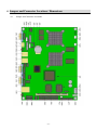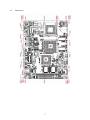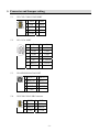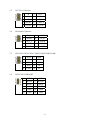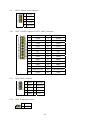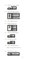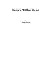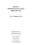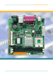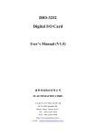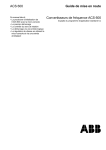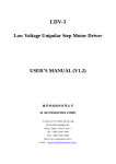
1
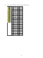
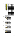
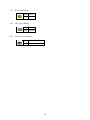
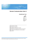
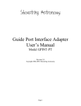
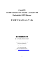
FA-8553
Intel Pentium® M /Intel® Celeron® M
Embedded CPU Board
USER’S MANUAL (V1.0)
健昇科技股份有限公司
JS AUTOMATION CORP.
台北縣汐止市中興路 100 號 6 樓
6F,No.100,Chungshin Rd.
Shitsu, Taipei, Taiwan, R.O.C.
TEL:886-2-2647-6936
FAX:886-2-2647-6940
http://www.automation.com.tw
E-mail:[email protected]
-1-
CONTENTS
1.
2.
3.
4.
5.
6.
Forward..........................................................................................................................................3
Features..........................................................................................................................................4
Specifications.................................................................................................................................5
Jumper and Connector Locations / Dimensions ............................................................................6
4.1
Jumper and Connector Locations .......................................................................................6
4.2
Dimensions .........................................................................................................................7
Connector and Jumper setting .......................................................................................................8
5.1
CN1/CN2:COM1/COM2 PORT.........................................................................................8
5.2
CN3: VGA PORT ...............................................................................................................8
5.3
CN4: KB/MS Mini Din PORT ...........................................................................................8
5.4
CN5/CN6/CN16:USB Connector.......................................................................................8
5.5
CN7:VGA Connector .........................................................................................................9
5.6
CN8:Audio Connector........................................................................................................9
5.7
CN9/CN12/CN23/CN24: COM3/COM4/COM5/COM6...................................................9
5.8
CN10/CN11:USB PORT ....................................................................................................9
5.9
CN13/CN14:Inverter Connector ........................................................................................10
5.10 CN15: LVDS2 Connector /CN17:LVDS1 Connector ........................................................10
5.11 CN18:GPIO Connector.......................................................................................................10
5.12 CN19:Temperature Sensor .................................................................................................10
5.13 CN20: Power Output Connector.........................................................................................11
5.14 CN21: LED Output Connector ...........................................................................................11
5.15 CN22 : SMBUS Connector ................................................................................................11
5.16 CN25:Power Input (12V) ...................................................................................................11
5.17 CN26: Power LED Connector............................................................................................11
5.18 CN27: IDE Active LED......................................................................................................11
5.19 CN28: Compact Flash Socket.............................................................................................11
5.20 CN29: K/B Lock Connector ...............................................................................................11
5.21 IDE1: Prinary HDD interface /IDE2:Secondary HDD interface .......................................12
5.22 LPT1: PRINT Connector....................................................................................................13
5.23 FAN1/FAN2: CPU FAN .....................................................................................................13
5.24 JP1/JP5: LVDS Voltage ......................................................................................................13
5.25 JP2: CPU VCCP Select.......................................................................................................13
5.26 JP3: CPU VCCA Select ......................................................................................................13
5.27 JP4: COMS Setup...............................................................................................................14
5.28 SW1: Reset Button .............................................................................................................14
5.29 SW2: Power On Button ......................................................................................................14
Ordering Information.....................................................................................................................15
-2-
1. Forward
Thank you for your selection of FA-8553 cpu card.
Any comment is welcome,
please visit our website: www.automation.com.tw for the up to date information.
-3-
2. Features
Support On-board 479 uFC-BGA ULV Intel ® Celeron ®M or Intel ® Celeron ® M or 479
uFC-PGA Intel® Pentium® M to 1GHz+
On Board 512MB DDR Memory
Dual Independent LVDS Display
High Performance Intel Ethernet (10Base-T/100Base-TX or Gigabit Ethernet)
6 USB, 6 COM, Multi-IO Supported
Type II Compact Flash for Embedded OS (Option)
Compact 5.25” ESB Form Factor, Low Profile Design
8 bit TTL IO
Wide Temperature Embedded SBC (-20 to +60 degree C )
12V DC only
-4-
3. Specifications
CPU : Intel® Pentium / Celeron® M
System Chipset : Intel ® 855GM/852GM
System Memory : On Board DDR Memory (512MB)
Display : Intel GMCH Integrated Graphics Controller with 64MB sharing memory.
SSD : Compact Flash Connector (under secondary master device)
Ethernet : ICH4 embedded MAC with Intel 82562EZ PHY 10/100 Ethernet Controller or Intel
82540EM Gigabit LAN Chipset
Audio :
18 Bit Audio Codec Chip
AC 97 2.3 complaint interface
Support Line_in / Line_out / Mic_in
Daughter Board 2Watts Amplifier (optional)
I/O :
USB Port : 6 , USB 2.0 ports
Serial Port : 6 , high speed 16550 fast UART serial ports with 12V/5V Power
IDE Interface : 2, Ultra ATA100 interface
FDD Interface : 1, supports 1.44/2.88MB and 3-mode floppy drive
Printer Port : On board printer port with SPP/EPP/ECP mode
Keyboard / Mouse : 2 , PS/2
TTL IO : 8, TTL IO ports
PCI Slot Extension : 32 bit PCI slot for Extension
H/W Monitoring : Winbond 83627HF support 7 voltage, 3 temperature and 2 fan-speed control
Watchdog Timer : Software Programmable Watchdog Timer with 1sec/minute timeout intervals
range from 1 to 255 seconds/minutes
Real Time Clock : 256 bytes CMOS RAM built-in ICH4 chipset Backup by non-rechargeable
Lithium cell battery
Power Requirement : 12V Single Power Required
Temperature : Operating: -20 to +60 degree C
Relative Humidity : Operating: 10% to 80% (non-condensing)
-5-
4. Jumper and Connector Locations / Dimensions
4.1
Jumper and Connector Locations
-6-
4.2
Dimensions
-7-
5. Connector and Jumper setting
5.1
5.2
CN1/CN2:COM1/COM2 PORT
1
DCD
6
DSR
2
RX
7
RTS
3
TX
8
CTS
4
DTR
9
RI
5
GND
CN3: VGA PORT
1
R
2
G
3
B
4
NC
5
GND
6
GND
7
GND
8
GND
9
VCC
10
GND
11
NC
12 V_DATA
13 HSYNC 14
VSYNC
15 V_CLK
5.3
CN4: KB/MS Mini Din PORT
1
KDATA
2 MDATA
3 KMGND 4 KMVCC
5.4
5
KCLK
6
MCLK
7
GND
8
GND
9
GND
CN5/CN6/CN16:USB Connector
1
5VSB
2
GND
3
DATA
4 DATA+
5 DATA+ 6
DATA
7
5VSB
GND
8
-8-
5.5
CN7:VGA Connector
1
R
2
VCC
3
G
4
GND
5
B
6
NC
8
V_DATA
7 HSYNC
9 VSYNC 10
5.6
5.7
5.8
V_CLK
CN8:Audio Connector
1
IN_L
2
AGND
3
AGND
4
IN_R
5
OUT_L
6
AGND
7
AGND
8
OUT_R
9
MIC IN
10
AGND
CN9/CN12/CN23/CN24: COM3/COM4/COM5/COM6
1
DCD
2
DSR
3
RX
4
RTS
5
TX
6
CTS
7
DTR
8
RI
9
GND
10
NC
CN10/CN11:USB PORT
1
5VSB
5
GND
2
DATA
6
DATA+
3
DATA+
7
DATA
4
GND
8
5VSB
G1
GND
G2
GND
G3
GND
G4
GND
-9-
5.9
CN13/CN14:Inverter Connector
1
P12V
2
GND
3
VCC
4
GND
5 ON/OFF
5.10
5.11
5.12
CN15: LVDS2 Connector /CN17:LVDS1 Connector
1
LCD+
2
LCD+
3
YAP0
4
YAM0
5
YAP1
6
YAM1
7
YAP2
8
YAM2
9
YAP3
10
YAM3
11
CLKAP
12
CLKAM
13
NC
14
NC
15
GND
16
GND
17
YBP0
18
YBM0
19
YBP1
20
YBM1
21
YBP2
22
YBM2
23
YBP3
24
YBM3
25
CLKBP
26
CLKBM
27
(DDCPCLK)
28
(DDCPDATA)
29
GND
30
GND
CN18:GPIO Connector
1 GPIP4 2
GPOP0
3 GPIP5
4
GPOP1
5 GPIP6
6
GPOP2
7 GPIP7
8
GPOP3
9
10 VCC
GND
CN19:Temperature Sensor
1
Sensor+
2
GND
- 10 -
5.13
5.14
CN20: Power Output Connector
1
VCC
2
GND
CN21: LED Output Connector
1
IDE LED
2
VCC3
3
Power LED
4
GND
5.15
CN22 : SMBUS Connector
5.16
CN25:Power Input (12V)
5.17
1
VIN
2
VIN
3
GND
4
GND
CN26: Power LED Connector
1 LED+
2
5.18
LED-
CN27: IDE Active LED
1 LED+
2
5.19
LED-
CN28: Compact Flash Socket
(Refer to the specification of CF card)
5.20
CN29: K/B Lock Connector
1
Keylock
2
GND
- 11 -
5.21
IDE1: Prinary HDD interface /IDE2:Secondary HDD interface
1
LDERST
2
GND
3
PD7
4
PD8
5
PD6
6
PD9
7
PD5
8
PD10
9
PD4
10
PD11
11
PD3
12
PD12
13
PD2
14
PD13
15
PD1
16
PD14
17
PD0
18
PD15
19
GND
20
NC
21
PDREQ
22
GND
23
PIOW
24
GND
25
PIOR
26
GND
27
PHDRDY
28
GND
29
PDACK
30
GND
31
IRQ14
32
NC
33
PDA1
34
NC
35
PDA0
36
PDA2
37
PDCS1
38 PDCS3
39 HD_LED1 40
GND
41
VCC
42
VCC
43
GND
44
GND
- 12 -
5.22
LPT1: PRINT Connector
1
STB
2
AFD
3
D0
4
ERR
5
D1
6
INIT
7
D2
8
SLIN
9
D3
10 GND
11
D4
12 GND
13
D5
14 GND
15
D6
16 GND
17
D7
18 GND
19
ACK
20 GND
21 BUSY 22 GND
5.23
5.24
5.25
23
PE
24 GND
25
SLCT
26 GND
FAN1/FAN2: CPU FAN
1
GND
2
12V
3
Sense
JP1/JP5: LVDS Voltage
1-2
3.3V
2-3
5V
JP2: CPU VCCP Select
1-2 Banias
2-3 Dothan
5.26
JP3: CPU VCCA Select
1-2 Banias
2-3 Dothan
- 13 -
5.27
JP4: COMS Setup
Short Clear
Open Normal
5.28
SW1: Reset Button
ON
Reset
OFF Normal
5.29
SW2: Power On Button
ON
PWR ON/OFF
OFF
Normal
- 14 -
6. Ordering Information
PRODUCT
JD50FA8553
JD50FA8553B
DESCRIPTIONS
FA-8553A Celeron M 1GHz 852GM
FA-8553B Celeron M 600MHz 852GM
- 15 -