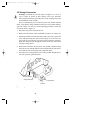
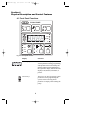
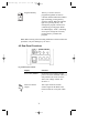
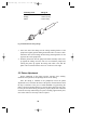
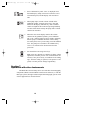
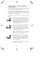
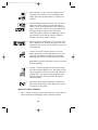
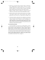
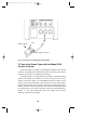
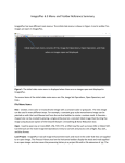
1
M7318140J.qxp
4/17/2006
2:17 PM
Page a
Model EP-1
Econo Pump
Instruction
Manual
Catalog Numbers
731-8140
731-8142
For Technical Service
Call Your Local Bio-Rad Office or
in the U.S. Call 1-800-4BIORAD
(1-800-424-6723)
M7318140J.qxp
4/17/2006
2:17 PM
Page b
Warranty
Model _________________________________________
Serial Number ___________________________________
Date of Delivery _________________________________
Warranty Period _________________________________
The Model EP-1 Econo Pump is warranted for 1 year against defects in
materials and workmanship.
If any defects should occur during this warranty period, Bio-Rad will
replace the defective parts without charge. However, the following defects
are specifically excluded:
1. Defects caused by improper operation.
2. Repair or modification done by anyone other than Bio-Rad
Laboratories or their authorized agent.
3. Use with tubings or fittings not specified by Bio-Rad Laboratories for
use with this pump.
4. Deliberate or accidental misuse.
5. Damage caused by disaster.
6. Damage due to use of improper solvent or sample.
This warranty does not apply to tubing, fittings, and fuses.
For inquiry or request for repair service, contact Bio-Rad Laboratories
after confirming the model and serial number of your instrument.
For Technical Service Call Your Local Bio-Rad Office or in the U.S.
Call 1-800-4BIORAD (1-800-424-6723).
M7318140J.qxp
4/17/2006
2:17 PM
Page c
Table of Contents
Section 1
Safety ..............................................................................1
Section 2
Introduction ...................................................................2
Section 3
Unpacking and Setting Up............................................3
3.1
3.2
Unpacking Instructions.............................................................3
Voltage Conversion...................................................................4
Section 4
Physical Description and Control Features ................5
4.1
4.2
4.3
Front Panel Functions...............................................................5
Rear Panel Functions................................................................7
Pump Base Features .................................................................8
Section 5
Tubing Selection and Installation ................................8
5.1
5.2
5.3
Tubing Selection .......................................................................8
Installation of Precut Bio-Rad Tubing .....................................9
Installation of Uncut Tubing...................................................10
Section 6
Stand Alone Operation ................................................11
Section 7
Operation with other Instruments.............................12
7.1
Use of the Pump with the Model 2110
Fraction Collector ...................................................................13
Use of the Econo Pump with the Model 2128
Fraction Collector ...................................................................16
Use of the Econo Pump with the
BioLogic System ....................................................................17
7.2
7.3
Section 8
Cleaning and Maintenance .........................................17
Section 9
Troubleshooting ...........................................................18
Section 10
Embedded Functions...................................................19
Appendix A
Technical Specifications ..............................................20
Appendix B
Operation of the Econo Pump When
Connected to Other Instruments ...............................21
Appendix C
Ordering Information .................................................22
M7318140J.qxp
4/17/2006
2:17 PM
Page 1
Section 1
Safety
!
Disconnect supply before servicing. No user serviceable parts inside,
refer servicing to Bio-Rad service personnel.
This instrument is intended for laboratory use only.
This product conforms to the “Class A” standards for electromagnetic
emissions intended for laboratory equipment applications. It is possible
that emissions from this product may interfere with some sensitive
appliances when placed nearby or in the same circuit as those
appliances. The user should be aware of this potential and take
appropriate measures to avoid interference.
1
M7318140J.qxp
4/17/2006
2:17 PM
Page 2
Section 2
Introduction
Fig. 2.1. Model EP-1 Econo Pump.
The Model EP-1 Econo Pump is a two-channel, bi-directional, variable
speed peristaltic pump for low-pressure chromatography and general
laboratory use. It offers a full range of features to facilitate ease of use as a
stand-alone pump or as a part of the BioLogic System. As a stand-alone
pump, the Model EP-1 Econo Pump delivers flow rates from 0.1 to 40
ml/min with the ability to self-calibrate the flow rate for 0.8, 1.6, and 3.2
mm ID tubing, displaying pump output in ml/min. The pump can be
programmed to control fraction collector parameters such as fraction size,
void volume, and total run volume. A membrane key panel with graphic
icon displays allows easy user interface.
2
M7318140J.qxp
4/17/2006
2:17 PM
Page 3
Section 3
Unpacking and Setting Up
3.1 Unpacking Instructions
Carefully remove the unit from the shipping box, lifting from the
handle on the back of the pump or from the bottom of the instrument.
Remove the plastic bag and inspect the instrument for any external damage.
Parts included with the Model EP-1 Econo Pump are illustrated in Figure
3.1. Check off all parts against the supplied packing list.
Your Model EP-1 Econo Pump was carefully tested at the factory and
was shipped in good working order. If any part is missing or damaged,
contact Bio-Rad Laboratories immediately. Refer to Figure 3.1 for the
proper identification designation of any missing or damaged part(s).
Tubing and Fitting
Starter Kit
Power Cord
Model EP-1 Econo Pump
Also includes: Instruction Manual
Fig. 3.1. Parts supplied with the Model EP-1 Econo Pump.
3
M7318140J.qxp
4/17/2006
2:17 PM
Page 4
3.2 Voltage Conversion
Warning: The Model EP-1 Econo Pump is shipped in its 120 V or
220 V version. To operate at other voltages, refer to the procedure
below. Failure to follow this procedure may result in damage to the unit
and invalidation of the warranty.
Prior to connecting the power cord to the power entry module and wall
outlet, verify that the voltage indicated on the power entry module matches
your line voltage. If it does not, use the following procedure to make the
conversion. Refer to Figure 3.2.
1. Disconnect the power cord from the unit.
2. Remove the fuse drawer with a small-blade screwdriver or similar tool.
3. Pull the fuse holder out of the fuse drawer and, if necessary, replace the
fuses with ones having the correct current rating. Use 0.50 A fuses for
100 V and 120 V operation; 0.25 A fuses for 220 V and 240 V operation.
Rotate the voltage selector through the window in the fuse drawer until
the proper voltage shows.
4. Reinsert the fuse drawer into the power entry module, with the locking
tab to the left. The voltage indicator will read right-side-up if the drawer
is oriented correctly. Press gently until it snaps into place.
5. Insert the power cord plug into the power entry module. Plug the power
cord into a properly grounded outlet.
Power
Entry Module
Voltage Selector
Fuse Drawer
Window
Fig. 3.2. Voltage conversion.
4
M7318140J.qxp
4/17/2006
2:17 PM
Page 5
Section 4
Physical Description and Control Features
4.1 Front Panel Functions
ECONO PUMP
ml
min
ml/min
%
0.8
1.6
Vo
Vt
3.2
CAL
Fig. 4.1. Front panel controls.
Display
Function
LED Display
The four-character display will show
various parameters during programming
and operation of the Econo Pump. The
indicator lights located immediately to
the right of the display indicate the units
displayed: ml, minutes, ml/minute, or
percent.
Arrow Keys
These keys are used for setting system
parameters when programming the
system, and for selecting which
parameter to display when running the
pump.
5
M7318140J.qxp
4/17/2006
ml
2:17 PM
Page 6
Indicator Lights
These lights indicate the units for the
value displayed on the LED display
located to the left. A flashing light
indicates that a value can be set using
the Arrow keys.
Run/Stop Key
This key is used to start or stop the
pump. It also has secondary functions
such as holding or aborting a method.
Purge Key
This key is used to prime and purge
tubing lines without disturbing the
primary speed setting of the pump.
When Purge is pressed, the pump will
run at maximum speed (25 rpm). The
purge key will not operate during a
fraction collection method.
Direction Key
This key changes the direction of
pump head rotation. The Econo Pump
must be stopped before the direction
can be changed.
Tubing Calibration Key
This key is used to select pre-programmed calibration settings for three
tubing sizes, or allows user calibration
for increased flow rate accuracy or
non-standard tubing sizes. The pump
must be stopped for this key to operate.
Fraction Collector Key
This key is used to set fraction size,
void volume (to move a diverter valve
to "collect" or "waste" positions), and
total run volume. The total run volume (Vt) may be used to program the
pump to automatically shut off after a
given volume has been delivered.
min
ml/min
%
0.8
1.6
3.2
CAL
Vo
Vt
6
M7318140J.qxp
4/17/2006
2:17 PM
Page 7
Program Run Key
This key is used to control a
programmed gradient or fraction
collection method. When the indicator
light is flashing, pressing this key
starts the method. When the indicator
light is lit, pressing this key will
interrupt the program, which can be
continued by pressing again. When
the LED displays “FAIL”, (indicating
a brief power outage has occurred),
pressing this key continues the
program.
Note: When entering values for tubing calibration or fraction collection
procedures, only the flashing keys are active.
4.2 Rear Panel Functions
Fig. 4.2. Rear panel sockets.
Display
Function
Power Entry Module
Grounded 3-pin receptacle for the
power cord. Also contained within is a
four-position (100 V/120 V/220 V/
240 V) line voltage selector. See
Section 3.2.
Fraction Collector
Output
This 8-pin connector sends an
advance signal to the Model 2110
Fraction Collector via System Cable
1.
7
M7318140J.qxp
4/17/2006
2:17 PM
Page 8
Diverter Valve Output
This 8-pin outlet sends a signal to the
Model SV-3 diverter valve, to divert
flow between collection devices.
Auxiliary Output
This 8-pin connector is for communication with the Model EM-1 Econo
UV Monitor and the BioLogic System.
4.3 Pump Base Features
The base of the Model EP-1 Econo Pump contains a 40-pin connector
for connection of the Econo Pump to the (discontinued) Econo System
Controller. This connector is not currently used with any systems sold by
Bio-Rad Laboratories, and should remain unused.
Section 5
Tubing Selection and Installation
5.1 Tubing Selection
The Model EP-1 Econo Pump may be used with most flexible tubing
having an inner diameter less than or equal to 3.2 mm (1/8"), and a wall
thickness of 1.0 mm or less, including silicone, Tygon, and PharMed.
Silicone tubing, the most inert of the three, is suitable for aqueous and polar
solutions. Tygon is suitable for most aqueous solutions. It will generally
have the shortest lifetime of the three. PharMed is the longest lasting of the
three, and will provide the most consistent flow rate over time. Table 5.1
shows approximate flow rate ranges with different tubing sizes. Flow rates
above 20 ml/min may be obtained by plumbing two channels of 3.2 mm
tubing through the pump and joining them at the output.
Table 5.1. Approximate Flow Rate Ranges
ubing Size
D x Wall)
Flow Rate Range ml/min
0.1
.2
.3
.4
.5
.6 .7 .8 .9 1.0
2
3
4
5
6
7 8 9 10
20
0.8 mm
1.6 mm
3.2 mm
Tubing length and the amount of tubing prestretch have a significant
effect on both flow rate calibration and reproducibility of flow. The PharMed
tubing supplied with the Econo Pump has been cut to a predetermined length
to accommodate tubing prestretch. (Silicon tubing in precut lengths is also
available from Bio-Rad. See ordering information in appendix C.)
8
M7318140J.qxp
4/17/2006
2:17 PM
Page 9
When using tubing other than precut tubing from Bio-Rad, the tubing
must be cut to the following lengths to accommodate prestretch:
Tubing
Length
Tygon, PharMed
179 mm +/- 1.5 (7.04" +/- 0.05)
Silicone
171 mm +/- 1.5 (6.75" +/- 0.05)
Install tubing onto the pump head as described in Section 5.2.
!
Warning: If using tubing other than the type supplied by Bio-Rad, make
sure the wall thickness is not greater than 1.0 mm. Using tubing with a
greater wall thickness can damage the pump and void your warranty.
5.2 Tubing Installation
1. Referring to Figure 5.1, pull the platen cam lever away from the pump
head to unlock the platen and slide the platen away from the pump head
frame assembly, exposing the rollers.
Fig. 5.1. Tubing installation.
2. Slip a lock-ring onto one end of the tubing. See below for the size and
color of each lock-ring. Insert a barbed female luer-fitting into the same
end until the tubing reaches the flange of the fitting. Clamp the luer-fitting into place by sliding the lock-ring along the tubing over the barbed
fitting (see Figure 5.2). Repeat on the other end of tubing.
Note: Use of lock-rings is required only when operating at pressures
above 10 psi.
9
M7318140J.qxp
4/17/2006
2:17 PM
Page 10
Lock-Ring Color
Tubing ID
Red
Orange
Yellow
0.8 mm (1/32")
1.6 mm (1/16")
3.2 mm (1/8")
Fig. 5.2. Attachment of tubing fittings.
3. Insert one end of the tubing into the tubing retaining bracket of the
pump head. Lightly pull the tubing around the rollers to remove slack.
Attach the other end of tubing into the tubing retaining bracket on the
opposite side of the pump head.
4. Slide the platen back into the pump head frame assembly until it rests
up against the tubing. Press the cam lever in toward the pump head,
locking the platen up against the tubing and rollers. Note that the
platen can be inserted with the cam lever on the left or the right.
5.3 Platen Adjustment
Proper adjustment of the platen pressure increases flow stability,
minimizes flow pulsation, and prolongs the life of the tubing.
Once the tubing is installed in the pumphead, loosen the platen
adjustment screw, located on the front of the platen, counterclockwise until
the stop is reached. For one piece of either PharMed or Tygon tubing, the
platen is properly adjusted at three to four full turns clockwise from stop.
For one piece of silicon tubing, the platen is properly adjusted two full turns
clockwise from stop. When using two pieces of tubing, approximately 50%
more turns clockwise from stop will be required.
10
M7318140J.qxp
4/17/2006
2:17 PM
Page 11
Note: Overtightening the platen adjustment screw will reduce flow rate
and shorten tubing life. If the platen is too loose, flow rate will decrease
as backpressure increases.
Section 6
Stand Alone Operation
The Model EP-1 Econo Pump functions as a stand-alone pump. By
specifying the pump tubing size, it allows you to enter a flow rate rather
than a nominal pump speed setting. (An uncalibrated Econo Pump will
display pump speed as percent of maximum rpm.) There are two ways to
calibrate the pump: through a preset tubing size or through a user
calibration procedure.
Flow Rate Calibration with Pre-Selected Tubing Sizes (0.8, 1.6,
and 3.2 mm ID)
0.8
1.
With the pump in Stop mode, install tubing as described
in Section 5.2.
2.
Press the key in the lower left-front of the pump panel
corresponding to the pump calibration feature, and
continue pressing until the indicator light corresponding
to either 0.8, 1.6, or 3.2 mm ID tubing is lit.
3.
The LED display reads ml/min for any of these pre-programmed tubing settings. If improved flow rate accuracy
is desired, see User Calibration Procedure below.
4.
The pump is now automatically calibrated for the specific
tubing size. Press the Run/Stop key to start flow. Increase
or decrease the pump speed with the Arrow keys.
1.6
3.2
CAL
ml
min
ml/min
%
ml
min
ml/min
%
User Calibration Procedure
1.
Install tubing as described in Section 5.2. Connect
pump inlet to a container of water or buffer. Connect a
length of tubing to the pump outlet.
2.
Run pump to purge air from tubing, then stop pump.
Place the end of the outlet tubing in an empty graduated
cylinder.
11
M7318140J.qxp
4/17/2006
0.8
2:17 PM
3.
Press Calibration key until “CAL” is displayed. Press
the Run/Stop key. Pump will run for 5 minutes at 25%
of maximum speed, and the display will count down
time.
4.
When pump stops, read the volume of fluid on the
graduated cylinder. Using the Arrow keys, enter this
amount on the display. Alternatively, when a suitable
volume of liquid has been collected, pressing Run/Stop
will turn off the timer and stop the pump. Enter volume
collected as described.
5.
When the value on the display matches the volume
collected in the graduated cylinder, press Calibration.
The “CAL” indicator light will glow steadily, indicating
that the pump is calibrated. DO NOT select a tubing
size at this point, even if you are using one of the standard
sizes. The pump will “remember” the calibration key
even if it is switched off or disconnected from the
power line.
6.
Set desired flow rate using arrow keys.
1.6
3.2
CAL
0.8
Page 12
1.6
3.2
CAL
Note: Flow rate depends on condition of tubing, platen
adjustment, and back pressure. For maximum flow rate
accuracy it may be necessary to recalibrate as the tubing
ages, when the tubing is replaced, if the platen is readjusted, or if back pressure changes significantly.
Section 7
Operation with other Instruments
The Model EP-1 Econo Pump can be used with other chromatography
components (Model 2110 and Model 2128 fraction collectors), or with the
BioLogic System, the high resolution liquid chromatography system. Each
of these applications is discussed below.
12
M7318140J.qxp
4/17/2006
2:17 PM
Page 13
7.1 Use of the Econo Pump with the Model 2110
Fraction Collector
The Econo Pump is capable of controlling the Model 2110 Fraction
Collector. The pump must be calibrated in order to run a fraction collector
program. See Section 6 for calibration instructions.
Use System Cable 1 (catalog number 731-8261) to connect the Econo
Pump to the fraction collector. Connect the 9-pin “D” connector to rear of
the Model 2110, and the mini-DIN plug to the rear port of the Econo Pump
with the collector icon. (See Figure 4.2.)
To program a simple time-based collection method, follow these
instructions.
1.
Press the Fraction Collector key on the pump front panel
to enter the fraction collector Edit mode. Note that the
fraction size and ml indicator lights are flashing, prompting entry of fraction size. Enter the fraction size in 0.1 ml
increments using the Arrow keys. After fraction size is
selected, press the Fraction Collector key once more to
confirm the fraction size.
2.
Enter a void volume (Vo ) in 1 ml increments using the
Arrow keys. This feature allows the user to begin collecting fractions only after a pre-set volume of liquid
(i.e., the void volume) has passed through the column.
Press the Fraction Collector key to confirm this value. If
a void volume is not desired, enter 0.
Vo
Vt
ml
min
ml/min
%
Vo
Vt
ml
min
ml/min
%
Note: The optional Model SV-3 Diverter Valve (catalog
number 731-8235) is required to use the void volume
feature of the Model EP-1 Econo Pump.
3.
Select the total run volume (Vt ) in 1 ml increments
using the Arrow keys.* If zero is entered and confirmed,
the fraction collection scheme is disabled. To resume
data entry, see Step 1 above. All values previously
entered remain in the memory until other values are
entered to replace them.
*
Note: The Econo Pump will automatically shut off upon
reaching the total run volume (Vt ).
Vo
Vt
ml
min
ml/min
%
13
M7318140J.qxp
4/17/2006
2:17 PM
4.
After selecting a Vt value, press the flashing Fraction
Collection key to enter the value. The flashing LED
display shows the estimated number of fractions to be
collected.
5.
Press the flashing Fraction Collection key once more to
enable the fraction collector. To actuate the fraction
collector, press the Program Run key after starting the
pump. (The fraction collector can be programmed with
the pump running or stopped.) After the fraction
collection program is initiated, the LED display shows
the progression of the fraction collection scheme in
minutes, to the nearest tenth of a minute.
6.
While a program is running, the user can use the Arrow
keys to display the ml of output, the progression of the
collection in min, the flow rate in ml/min, or the percent
of total run-time.
7.
To abort the fraction collection scheme at any time
during the program, press the Run/Stop key twice. The
pump will stop, and the LED display will read OFF,
indicating abortion of the fraction collection program.
Vo
Vt
Vo
Vt
ml
min
ml/min
%
ml
Page 14
min
ml/min
%
Note: When a program is aborted, it can only be restarted
from the beginning.
8.
To place a collection program that has begun on Hold,
press the lit Program Run key once. The pump will stop
and the program will be held. To resume the collection
program, press once again. Pressing the Run/Stop key
while the program is on hold will abort the fraction
collection scheme.
9.
When the fraction collection program is complete, the
pump stops and the display reads "END." Press any key
to return to the ready mode.
Notes on Fraction Collection:
1. After a fraction collection program has begun, the pump cannot be
turned off without terminating the fraction collection program.
14
M7318140J.qxp
4/17/2006
2:17 PM
Page 15
2. During the Vo period of the fraction collection scheme (as indicated by
the Vo indicator light), the fraction collector is not active. To collect
fractions during this void volume period, cancel Vo by pressing the
Fraction Collector key. The fraction collector will start, with the LED
display indicating the time-progression of the collection scheme.
3. When the fraction collector is disabled by pressing the Fraction
Collector key, the fraction collector carousel will advance one tube.
4. When the fraction collector indicator light on the pump is lit, the Model
2110 Fraction Collector will be put into remote mode. Only the
manual advance keys will be active, and the Model 2110 display reads
---.
5. The fraction collection control feature of the Model EP-1 Econo Pump
can be used to turn off the pump even if a fraction collector is not
connected. Simply enter 0 for fraction size. After confirming the Vt
value entered (the Vt light will be lit solid), start the pump, if not
already running; then press the flashing Program Run key. The LED
display will show time elapsed. The pump will stop automatically when
the total run volume has been delivered.
Use of the Diverter Valve
The optional Model SV-3 diverter valve (catalog number 731-8235)
provides a means to divert the eluant stream from a fraction collector to a
waste receptacle or other collection device during a fraction collection
program. If the void volume function (Vo ) of the collection scheme is
enabled with the diverter valve in place, the eluant stream will be diverted
away from the fraction collector during that period. When that period is
over, the eluant stream will be diverted to the fraction collector. Whenever
the diverter valve changes from waste to collect, or vice versa, an event
mark is generated. This will appear as a deflection on the chart recorder.
For connection of the diverter valve, see Figure 7.1.
15
M7318140J.qxp
4/17/2006
2:17 PM
Outlet to Waste
Page 16
Inlet
Outlet to Collector
Fig. 7.1. Connection of the Model SV-3 Diverter Valve.
7.2 Use of the Econo Pump with the Model 2128
Fraction Collector
The Econo Pump is capable of controlling the Model 2128 Fraction
Collector. The pump must be calibrated in order to run a fraction collector
program. See Section 6 for calibration instructions.
Use System Cable 15 (catalog number 731-8286) to connect the Econo
Pump to the Model 2128 Collector. If the SV-3 diverter valve is used,
connect it as shown in Figure 7.1. If the Model 2128 Diverter Valve is used,
connect one end of System Cable 3 to the diverter valve port on the Econo
Pump, and connect the other end to the mini-DIN port on the Model 2128
Fraction Collector. This cable transmits flow diversion information from
the Econo Pump to the collector. Program collection as demonstrated in
Section 7.1. For more information about the Model 2128 Fraction
Collector, consult the user manual.
16
M7318140J.qxp
4/17/2006
2:17 PM
Page 17
7.3 Use of the Econo Pump with the BioLogic
System
The Econo Pump can be controlled by the BioLogic System and used
as a sample loading pump.
Note: The Econo Pump must have v2.12 software in order to accept
on/off commands from the BioLogic System. See Section 10.1 for
instructions on how to check the software version. If an upgrade is
required, contact your local Bio-Rad representative.
To connect the Econo Pump to the BioLogic, use System Cable 7
(catalog number 731-8267). Connect the mini-DIN end of the cable to the
AUX port of the Econo Pump, and make a bare wire connection to the AUX
port of the BioLogic Workstation (RED to port 6, BLUE to port 9).
To connect the wires to the AUX port of the BioLogic System, turn the
small flathead screwdriver counterclockwise to back out the screw. Insert
the bare wire into the port and turn the screwdriver clockwise to secure the
connection. Be sure to calibrate the pump and set a flow rate prior to using
the Econo Pump with the BioLogic System, since the BioLogic sends only
“on/off” commands to the Econo Pump. To program the Econo Pump as a
sample loading pump with the BioLogic System, refer to the BioLogic
System user manual.
Section 8
Cleaning and Maintenance
The Model EP-1 Econo Pump requires very little maintenance to assure
reliable operation. The procedures outlined below will insure maximum
pump life:
•
Check tubing regularly for signs of cracking and wear. If any exist,
replace the tubing.
•
For optimal tubing life, use a slow to medium pump speed. To increase
throughput, increase tubing size to obtain the desired output.
•
When not in use, tubing should be removed from the pump to prevent
deformation of the tubing. Remove the platen and relax the tubing by
unhooking one end of the tubing from the tubing bracket.
•
To prevent the formation of precipitates around the pump head and on
the membrane key panel, promptly remove any spills. Clean with
deionized water.
17
M7318140J.qxp
4/17/2006
2:17 PM
Page 18
Section 9
Troubleshooting
Problem
Possible Cause
Solution
Pump displays
"OUT"
Power surge or
brownout
1. Turn the power switch off.
2. Press and hold down the
down arrow key and the CAL
key simultaneously while turning
the power switch on. This will
reset the pump. If the pump was
previously calibrated you will
have to recalibrate it.
Pump displays
"FAIL"
Power outage
If you wish to continue a run in
progress, press program run key.
Otherwise, press the run/stop
key.
Pump will not run
(no LEDs lit)
No power
Verify that powercord is plugged
in and the power switch is turned
on.
Fuses
Check that proper fuses are
installed and intact.
Insure that the calibration indicatorlight is not flashing. For pump
to run, this light must either be
off or steadily lit.
Liquid remains
stationary in tubing
Flow rate not
consistent
Platen not adjusted
Platen too loose. Turn platen
screw clockwise just until liquid
begins moving within tubing.
Clogged tubing,
valves, or fittings
Check tubing, fittings, and valves
for obstructions.
Damaged tubing
Check pump tubing for damage.
Replace damaged tubing.
Pump tubing
damaged or worn out
Replace tubing.
Platen adjustment
incorrect
Adjust platen.
Wrong tubing size
selected
Re-select tubing size on front
panel of pump.
18
M7318140J.qxp
4/17/2006
Problem
2:17 PM
Page 19
Possible Cause
Solution
Large change in
back pressure or
fluid viscosity
Re-calibrate flow.
Restriction on inlet
side
Remedy
Excessive tubing
wear
Platen too tight
Turn platen adjustment screw
clockwise to stop flow, then
clockwise until flow starts.
Cannot calibrate
pump
Pump must be
stopped in order to
calibrate pump
Insure that pump is stopped.
Error message
displayed upon
powering up (ER ##)
Contact Bio-Rad Technical
Service
Section 10
Embedded Functions
During a technical service call, you may be asked to perform tasks
which require you to press combinations of keys. These tasks are defined
below.
10.1 Software Confirmation
To check the version of software installed in the Econo Pump, simultaneously hold down the direction key (in the upper left corner) and the
“down” arrow key on the front panel of the Econo Pump. The four digit
display should display “v2.01” or higher.
10.2 Warm Reboot
You may be asked to perform a warm reboot if the Econo Pump software is not functioning properly. To initiate a warm reboot, press the
Tubing Calibration and Down Arrow keys simultaneously and hold for 3
seconds.
10.3 Cold Reboot
A cold reboot may be necessary if the warm reboot was unsuccessful.
Turn off the pump and hold the Tubing Calibration and Down Arrow keys
while turning the pump back on. Hold the two keys until the display
stabilizes.
19
M7318140J.qxp
4/17/2006
2:17 PM
Page 20
Appendix A
Technical Specifications
Number of channels
2
Flow rate range (per channel)
0.1-20 ml/min (depending on tubing diameter)
Pump head speed
25 rpm maximum
Tubing diameter
0.4 mm ID to 3.2 mm ID
Speed adjustment
1%
Speed stability
1% of full scale
Maximum counterpressure
30 psi (2 kg/cm2 or bars)
Motor
DC speed controlled, 55 watts
Line voltage
90-132 VAC
180-265 VAC
47-63 Hz
Dimensions
143 x 202 x 222 mm
(W x D x H) with pumphead
Weight
3.3 kg
Operating temperature
4 to 40 °C
Material of construction
polypropylene and other solvent
resistant plastics
Regulatory
CSA: C22.2 No.151-M1986
Compliance
TÜV: EN61010-1:1993
CE: EN55011:1991 Class A
EN50082-2:1995
20
M7318140J.qxp
4/17/2006
2:17 PM
Page 21
Appendix B
Operation of the Model EP-1 Econo Pump When
Connected to Other Instruments
The Model EP-1 Econo Pump provides a variety of output signals which
can be used to control the operation of non Bio-Rad fraction collectors, or
to communicate with non Bio-Rad UV monitors and recording devices.
Communication is accomplished through two standard 8-pin mini-DIN
sockets on the rear panel of the pump. The third socket is for the operation
of the Model SV-3 Diverter Valve (see Figure 4.2). Bio-Rad offers an
accessory breakout cable (System Cable 7), which has an 8-pin mini-DIN
connector at one end and loose wires on the other, for connection to other
instruments. Output signals are TTL compatible. To use these signals, you
must insure that the circuit external to the Model EP-1 Econo Pump does not
draw more than 15 milliamperes of current. The following table describes
the two rear panel mini-DIN connector pinouts.
Table B. Rear Panel Pinouts
Pinout
*
1
2
3
4
5
6
7
8
Signal Type
Pinout
Shield
Fraction Advance
(low-going output)
No Contact
No Contact
No Contact
Fraction Advance
(high-going output)
No Contact
Ground
Fraction Advanced Marks to
Recorder (low-going input)
21
*
1
Signal Type
2
3
4
5
Shield
Start/Enable
(output)
No Contact
Mark A (output)
No Contact
No Contact
6
7
8
Pen (output)
Ground
Mark B (output)
M7318140J.qxp
4/17/2006
2:17 PM
Page 22
Appendix C
Ordering Information
Catalog
Number
Product Description
Model EP-1
Econo Pump
731-8140
Model EP-1 Econo Pump, 110 V (USA power cord), with
tubing set and starter fittings kit
731-8142
Model EP-1 Econo Pump, 220 V (no power cord), with
tubing set and starter fittings kit
731-8145
Model EP-1 Pumphead Assembly
731-8235
Model SV-3 Diverter Valve
Tubing and Accessories
731-8210
Silicone Tubing, 0.8 mm ID, 0.8 mm wall, 10 m
731-8211
Silicone Tubing, 1.6 mm ID, 0.8 mm wall, 10 m
731-8212
Silicone Tubing, 3.2 mm ID, 0.8 mm wall, 10 m
731-8214
Tygon Tubing, 0.8 mm ID, 0.8 mm wall, 10 m
731-8215
Tygon Tubing, 1.6 mm ID, 0.8 mm wall, 10 m
731-8207
PharMed Tubing, 0.8 mm ID, 1.0 mm wall, 10 m
731-8208
PharMed Tubing, 1.6 mm ID, 1.0 mm wall, 10 m
731-8209
PharMed Tubing, 3.2 mm ID, 1.0 mm wall, 10 m
731-8240
Silicone Tubing Kit, 0.8 mm ID, 20 precut lengths and 4
sets of fittings
731-8241
Silicone Tubing Kit, 1.6 mm ID, 20 precut lengths and 4
sets of fittings
731-8242
Silicone Tubing Kit, 3.2 mm ID, 20 precut lengths and 4
sets of fittings
731-8247
PharMed Tubing Kit, 0.8 mm ID, 20 precut lengths and 4
sets of fittings
731-8248
PharMed Tubing Kit, 1.6 mm ID, 20 precut lengths and 4
sets of fittings
731-8249
PharMed Tubing Kit, 3.2 mm ID, 20 precut lengths and 4
sets of fittings
22
M7318140J.qxp
4/17/2006
Catalog
Number
731-8220
2:17 PM
Page 23
Product Description
Low Pressure Fittings Kit, includes over 250 male and
female luer connectors, 2- and 3-way stopcocks, and tubing
connectors
Cables
731-8261
System Cable 1, 8-pin mini-DIN to DB-9 connector. For
connection of Model 2110 Fraction Collector to the Econo
Pump, to the BioLogic LP
731-8262
System Cable 2, 8-pin mini-DIN to 8-pin standard DIN. For
connection of Model 1327 Chart Recorder to the Econo UV
Monitor
731-8264
System Cable 4, 8-pin mini-DIN to banana cable. To connect Econo UV Monitor to the Model 1327 Chart Recorder
731-8267
System Cable 7, 8-pin mini-DIN to bare wires. To connect
Econo Pump to the BioLogic System
Model 2110 Fraction Collector
731-8122
Model 2110 Fraction Collector, 100/120 V
731-8120
Model 2110 Fraction Collector, 220/240 V
Model 2128 Fraction Collector
731-8123
Model 2128 Fraction Collector, 100/120 V
731-8124
Model 2128 Fraction Collector, 220/240 V
Bio-Rad sells a complete line of integrated chromatography systems
for protein purification. For more information on the BioLogic System
family of products, contact your local Bio-Rad representative.
PharMed and Tygon are the registered trademarks of the Norton
Company.
23
M7318140J.qxp
4/17/2006
2:17 PM
Page 24
Bio-Rad
Laboratories
Life Science
Group
Bulletin 0000
US/EG
Web site www.bio-rad.com USA (800) 4BIORAD Australia 02 9914 2800
Austria (01) 877 89 01 Belgium 09-385 55 11 Brazil 55 21 507 6191
Canada (905) 712-2771 China 86-10-8201-1366/68 Denmark 45 44 52-1000
Finland 358 (0)9 804 2200 France 01 47 95 69 65 Germany 089 318 84-177
Hong Kong 852-2789-3300 India (91-124) 6398112/113/114 Israel 03 951 4124
Italy 34 91 590 5200 Japan 03-5811-6270 Korea 82-2-3473-4460
Latin America 305-894-5950 Mexico 52 5 534 2552 to 54
The Netherlands 0318-540666 New Zealand 64-9-4152280 Norway 47-23-38-41-30
Russia 7 095 979 98 00 Singapore 65-2729877 Spain 34-91-590-5200
Sweden 46 (0)8-55 51 27 00 Switzerland 061-717-9555 United Kingdom 0800-181134
Rev A
00-000
0000
Sig 1200
M7318140 Rev J