1
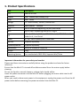
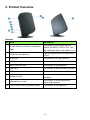
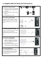
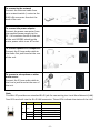
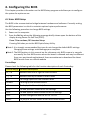
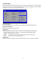
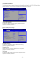
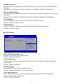
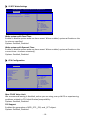
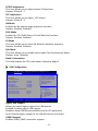
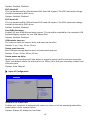
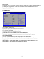
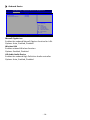
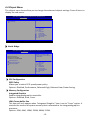
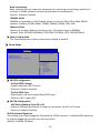
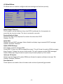
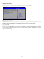
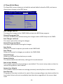
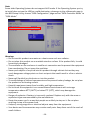
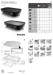
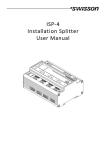
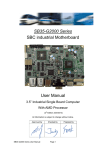
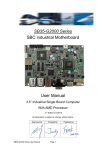
User’sManual Sapphire EDGE-HD Mini PC -1 1. Product Specifications Item Description CPU AMD APU E450 Chipset AMD® Hudson‐M1 (A50M) Chip RAM 4GB – DDR3 Storage 2.5'' SATA 250GB / 320GB / 500GB HDD Graphics AMD RadeonTM HD6320 LAN Built‐in Ethernet supporting 10/100/1000 Mbps WIFI Built‐in WIFI supporting IEEE 802.11 b/g/n I/O VGA x1, HDMI x1, RJ45x 1, USB 3.0 Ports x2, USB 2.0 Ports x2, Audio‐In x1, Line Out x1 Power AC 100~240V 50/60Hz,19v~3.42A 65W Monitor Supplied separately Keyboard/Mouse Supplied separately Dimensions 19.3(L) X 14.8(W) X 2.2(H) cm Weight 530g Operating System Pre‐installed with FREE DOS; Supports Win7/Vista Important information for your safety and comfort Please read these instructions carefully before using the product and save for future reference. Ensure that the Mini‐PC is turned off and disconnected from the mains supply before cleaning Do not use liquid or aerosol cleaners, a damp cloth should suffice Insert the power connector into the Mini PC before plugging the mains cable into the AC power outlet. When you need to disconnect power to the equipment, unplug the power cord from the AC power outlet before removing the power connector from the Mini PC. -2 2. Product Overview Features No. Item 1 Power Switch and Power Indication light 2 HDD Activity Indicator 3 VGA port Description The power switch allows you to switch the Mini PC ON or OFF. The light will glow when the power is on Light will glow when the hard disk is in use To connect to a VGA monitor 4 HDMI port To connect to an HDMI monitor 5 Rear USB 2.0 Ports To connect to USB devices 6 LAN Port To connect to an Ethernet LAN cable 7 DC Input 8 Audio out jack 9 Microphone in jack To connect the power supply To connect to headphones or speakers To connect to a microphone or other audio source To connect to USB devices. 10 Front USB3.0 Ports (remove cover) -3 3. Sapphire Mini PC Setup and Connections To attach the Desktop Stand (1). Feed the thumb screw provided through the hole in the base of the stand (2). Align stand with the base of the Mini PC (3). Hand tighten the screw To connect to a VGA display Connect the VGA monitor or other display device to the 15 pin D‐Sub connector found on the rear of the unit. To connect to an HDMI display / TV Connect the HDMI monitor or other display device to the HDMI connector found on the rear of the unit. To connect to a DVI display (1). Connect the HDMI to DVI adapter included with the Mini PC to the HDMI port found at the rear of the unit. (2). Connect the DVI monitor to the female DVI port on the adapter. To connect USB devices Connect USB devices to the USB ports found both at the rear of the unit and under the cover on the front of the unit. -4 To connect to the network Connect the Ethernet cable from your network switch / router to the RJ45 LAN connector found at the back of the unit. To connect the power adapter Connect the power connector from the supplied power supply to the DC – In connector found on the rear of the unit BEFORE attaching the mains power cable to an AC outlet. To connect speakers or headphones Connect the 3.5mm audio cable to the Audio Out jack found at the rear of the unit. To connect a microphone or other audio source Connect the 3.5mm audio cable to the Line In jack found at the rear of the unit. Note: This Mini PC provides one standard RJ‐45 jack for connecting to a Local Area Network (LAN). Two LEDs are built into the RJ‐45 LAN connector. These LEDs indicate the status of the LAN. LED LED Color LED state Indicates Off LAN link is not established A B Green On LAN link is established Blinking LAN activity is occurring N/A Off 10 Mb/s data rate Green On 100 Mb/s data rate Yellow On 1000 Mb/s data rate -5 4. Configuring the BIOS This chapter provides information on the BIOS Setup program and allows you to configure the system for optimum use. 4‐1 Enter BIOS Setup The BIOS is the communication bridge between hardware and software. Correctly setting the BIOS parameters is critical to maintain optimal system performance. Use the following procedure to change BIOS settings. 1. Power on the computer. 2. Press the Del key when the following message briefly shows upon the bottom of the display during Power On Self Test (POST). Press F1 to continue, DEL to enter Setup. Pressing Del takes you to the BIOS Aptio Setup Utility. Note1: It is strongly recommended that you do not change the default BIOS settings. Changing some settings could damage your computer. Note2: The BIOS options in this manual are for reference only. BIOS screens in manuals are usually the first BIOS version when the board is released and may be different from your purchased motherboard. Users are welcome to download the latest BIOS version from our official website ControlKeys Please check the following table for the function description of each Controlkey. Control Key(s) Function Description / Moves cursor left or right to select Screens / Moves cursor up or down to select items + / ‐ To change option for the selected items <Enter> To bring up the selected screen <F1> To display the General Help Screen <F2> To load previous values for all the settings <F3> To load optimal default values for all the settings <F4> To save changes and exit the SETUP UTILITY <ESC> To jump to the Exit Screen or exit the current screen -6 4‐2 Main Menu When entering the Aptio Setup Utility, the main menu screen appears. This main menu includes the system overview and displays the basic system configuration, such as BIOS information, memory size and system date/time. Aptio Setup Utility ‐ Copyright (C) 2010 American Megatrends, Inc. Main Advanced BIOS Information BIOS Vendor Core Version Compliancy Project Version Build Date and Time Memory Information Total Memory System Date System Time Access Level Chipset Boot American Megatrends 4.6.4.0 UEFI 2.1 1A0VU 0.41 x64 10/14/2011 15: 12 : 34 2032 MB (DDR3) [Wed 10/19/2011] [13:55:02] Administrator Security Save & Exit Set the Date. Use Tab to switch between Data elements. : Select Screen : Select Item Enter: Select +/‐: Change Opt. F1: General Help F2: Previous Values F3: Optimized Defaults F4: Save and Exit ESC: Exit Version 2.10.1208. Copyright (C) 2010 American Megatrends, Inc. BIOS Information This field displays the current BIOS version, build date and ID information etc.. Memory Information Displays current system memory size. System Date Allows you to set the system date. The format is <Day><Month><Date><Year>. [Day] Weekday from Sun. to Sat., this is automatically displayed by BIOS. [Month] The month from 1 to 12. [Date] The date from 1 to 31 can be keyed by numeric function keys. [Year] The year can be adjusted by users. System Time Allows you to set the system time. The time format is <hour>:<minute>:<second>. -7 4‐3 Advanced Menu The Advanced menu items allow you to change the settings for the CPU, USB and other system devices. Press <Enter> to display the configuration options. Aptio Setup Utility ‐ Copyright (C) 2010 American Megatrends, Inc. Main Advanced Legacy OpROM Support Launch PXE OpROM PCI Subsystem Settings ACPI Settings S5 RTC Wake Settings CPU Configuration USB Configuration Super IO Configuration H/W Monitor Onboard Device Chipset Boot [Disabled] Security Save & Exit Enables or disable Boot option for legacy network devices : Select Screen : Select Item Enter: Select +/‐: Change Opt. F1: General Help F2: Previous Values F3: Optimized Defaults F4: Save and Exit ESC: Exit Version 2.10.1208. Copyright (C) 2010 American Megatrends, Inc. Launch PXE OpROM Enables the Boot option for legacy network devices. Options: Enabled, Disabled. PCI Subsystem Settings Aptio Setup Utility ‐ Copyright (C) 2010 American Megatrends, Inc. Advanced PCI Bus Driver Version V 2.03.00 PCI Express Device Settings Relaxed Ordering Extended Tag No Snoop Maximum Payload Maximum Read Request [Disabled] [Disabled] [Enabled] [Auto] [Auto] PCI Express Link Settings ASPM Support [Disabled] WARNING: Enabling ASPM may cause some PCI‐E devices to fail Extended Synch [Disabled] Enables or Disables PCI Express Device Relaxed ordering. : Select Screen : Select Item Enter: Select +/‐: Change Opt. F1: General Help F2: Previous Values F3: Optimized Defaults F4: Save and Exit ESC: Exit Version 2.10.1208. Copyright (C) 2010 American Megatrends, Inc. Relaxed Ordering Enables the PCI Express device Relaxed Ordering. Options: Enabled, Disabled. Extended Tag Allows device to use 8‐bit TAG field as a requester. Options: Enabled, Disabled No Snoop Enables the No Snoop function of PCI Express device. Options: Enabled, Disabled. -8 Maximum Payload Sets the Maximum Payload size of PCI Express Device or allows the System BIOS to select the value. Options: Auto, 128 Bytes, 256 Bytes, 512 Bytes, 1024 Bytes, 2048 Bytes, 4096 Bytes. Maximum Read Request Sets the Maximum Read Request of PCI Express Device or allows the System BIOS to select the value. Options: Auto, 128 Bytes, 256 Bytes, 512 Bytes, 1024 Bytes, 2048 Bytes, 4096 Bytes. ASPM Support Sets the ASPM level, select “Force L0” can force all links to L0 state. Options: Disabled, Auto, Force L0. Extended Synch If select “Enabled”, allows generation of Extended Synchronization patterns. Options: Enabled, Disabled. ACPI Settings Aptio Setup Utility ‐ Copyright (C) 2010 American Megatrends, Inc. Advanced Enable ACPI Auto Configuration Enable Hibernation ACPI Sleep State Lock Legacy Resources [Disabled] [Enabled] [S3 (Suspend to RAM)] [Disabled] Enables or Disables BIOS ACPI Auto Configuration. : Select Screen : Select Item Enter: Select +/‐: Change Opt. F1: General Help F2: Previous Values F3: Optimized Defaults F4: Save and Exit ESC: Exit Version 2.10.1208. Copyright (C) 2010 American Megatrends, Inc. Enable ACPI Auto Configuration Enables the BIOS ACPI auto configuration. Options: Enabled, Disabled. Enable Hibernation Enables system ability to Hibernate (OS/S4 Sleep Sate). This option may be not effective with some OS. Options: Enabled, Disabled. ACPI Sleep State Selects the ACPI state used to suspend system. Options: Suspend Disabled, S3 (Suspend to RAM). Lock Legacy Resources When enabled (locked), this option prevents the operating system from modifying assignments for legacy resources. Options: Enabled, Disabled. -9 S5 RTC Wake Settings Aptio Setup Utility ‐ Copyright (C) 2010 American Megatrends, Inc. Advanced Wake system with Fixed Time Wake system with Dynamic Time [Disabled] [Disabled] : Select Screen : Select Item Enter: Select +/‐: Change Opt. F1: General Help F2: Previous Values F3: Optimized Defaults F4: Save and Exit ESC: Exit Version 2.10.1208. Copyright (C) 2010 American Megatrends, Inc. Wake system with Fixed Time Enable or disable system wake on alarm event. When enabled, system will wake on the hr:min:sec specified. Options: Enabled, Disabled. Wake system with Dynamic Time Enable or disable system wake on alarm event. When enabled, system will wake on the current time + Increase minutes(s). Options: Enabled, Disabled. CPU Configuration Aptio Setup Utility ‐ Copyright (C) 2010 American Megatrends, Inc. Advanced CPU Configuration Limit CPUID Maximum PSS Support PSTATE Adjustment PPC Adjustment NX Mode SVM Mode C6 Mode Cpb Mode Node 0 Information Disabled for Windows XP. [Disabled] [Enabled] [PState 0] [PState 0] [Enabled] [Enabled] [Enabled] [Auto] : Select Screen : Select Item Enter: Select +/‐: Change Opt. F1: General Help F2: Previous Values F3: Optimized Defaults F4: Save and Exit ESC: Exit Version 2.10.1208. Copyright (C) 2010 American Megatrends, Inc. Max CPUID Value Limit We recommend leaving it disabled, unless you are using a very old OS or experiencing problems related to CPU identification/compatibility. Options: Enabled, Disabled. PSS Support Enables the generation of ACPI_PCC,_PSS, and _PCT object. Options: Enabled, Disabled. - 10 PSTATE Adjustment This item allows you to adjust startup P‐State level. Options: PState 0 ~7. PPC Adjustment This item allows you to adjust _PPC object. Options: PState 0 ~2 NX Mode Enables the No‐execute page protection function. Options: Enabled, Disabled. SVM Mode Enables the CPU SVM( Secure Virtual Machine) function. Options: Enabled, Disabled. C6 Mode This item allows you to select C6 State for Nehalem processor. Options: Enabled, Disabled. Cpb Mode This item allows you to disable turbo mode Core Performance Boost. Options: Auto, Disabled. Node 0 Information This field displays the CPU information related to Node 0. USB Configuration Aptio Setup Utility ‐ Copyright (C) 2010 American Megatrends, Inc. Advanced USB Configuration USB Devices: 1 Keyboard, 1 Mouse Legacy USB Support [Enabled] USB3.0 Support [Enabled] XHCI Hand‐off [Enabled] EHCI Hand‐off [Disabled] Part 60/64 Emulation [Enabled] USB Hardware delays and time‐outs: USB transfer time‐out [20 sec] Device reset time‐out [20 sec] Device power‐up delay [Auto] Enables Legacy USB support; AUTO option disables legacy support if no USB devices are connected, DISABLED option will keep USB devices available only for EFI application. : Select Screen : Select Item Enter: Select +/‐: Change Opt. F1: General Help F2: Previous Values F3: Optimized Defaults F4: Save and Exit ESC: Exit Version 2.10.1208. Copyright (C) 2010 American Megatrends, Inc. Legacy USB Support Allows you select legacy support for USB devices. Enabled: Enables Legacy USB support. Disabled: Keep USB devices available only for EFI application. Auto: Disables legacy support if no USB devices are connected. USB3.0 Support Enables USB3,0 (XHCI) controller support. - 11 Options: Enabled, Disabled. XHCI Hand‐off This is a workaround for OSes without XHCI hand‐off support. The XHCI ownership change should be claimed by XHCI driver. Options: Enabled, Disabled. EHCI Hand‐off This is a workaround for OSes without EHCI hand‐off support. The EHCI ownership change should be claimed by EHCI driver. Options: Enabled, Disabled. Part 60/64 Emulation Enables I/O port 60h/64h emulation support. This should be enabled for the complete USB keyboard legacy support for non‐USB aware OSes. Options: Enabled, Disabled. USB transfer time‐out The time‐out value for control, bulk, and interrupt transfers. Options: 1 sec, 5 sec, 10 sec, 20 sec. Device reset time‐out Sets USB mass storage devices start unit command time‐out. Options: 10 sec, 20 sec, 30 sec, 40 sec. Device power‐up delay Maximum time the device will take before it properly reports itself to the Host controller. ‘Auto’ uses default values; for a Root port it is 100ms, for a Hub port the delay is taken from Hub descriptor. Options: Auto, Manual. Super IO Configuration Aptio Setup Utility ‐ Copyright (C) 2010 American Megatrends, Inc. Advanced Super IO Configuration Super IO Chip Restore on AC Power Loss EuP Function Set Parameters of Serial Port 0. Fintek F71808 [Always Off] [Disabled] : Select Screen : Select Item Enter: Select +/‐: Change Opt. F1: General Help F2: Previous Values F3: Optimized Defaults F4: Save and Exit ESC: Exit Version 2.10.1208. Copyright (C) 2010 American Megatrends, Inc. Restore on AC Power Loss Enables your computer to automatically restart or return to its last operating status after power returns from a power failure. Options: Always off, Always on, Last State. - 12 EuP Function Enables the EuP (Energy Using Products) function, allows BIOS to switch off some power at S5 state to get system ready for the EuP requirement to reduce power consumption. Options: Enabled, Disabled. H/W Monitor Aptio Setup Utility ‐ Copyright (C) 2010 American Megatrends, Inc. Advanced PC Health Status Fan Mode Setting. CPU Temperature System Temperature CPU Fan Speed System Fan Speed VCC3V CPU Vcore +1V VDIMM +1.1V +1.8V VSB3V VBAT : +58 C : +44 C : 6024 RPM : N/A : +3.328 V : +1.304 V : +1.504 V : +1.568 V : +1.080 V : +1.880 V : +3.340 V : +3.312 V CPU Fan Mode Setting Temperature Limit of Highest Temperature Limit of Lowest Fan Highest Setting Fan Lowest Setting [SmartFan] 60 30 100 50 : Select Screen : Select Item Enter: Select +/‐: Change Opt. F1: General Help F2: Previous Values F3: Optimized Defaults F4: Save and Exit ESC: Exit Version 2.10.1208. Copyright (C) 2010 American Megatrends, Inc. CPU / System Temperature Displays the current CPU and system temperature. CPU /System Fan Speed Displays the current CPU and System Speed VCC3V/CPU Vcore/+1V/VDIMM/+1.1V/+1.8V/VSB3V/VBAT The current voltages are automatically detected and displayed by the system. CPU Fan Mode Setting This item controls the speed of the various fans on the motherboard. SmartFan: When you want the speed of the fans automatically controlled based on temperature. Manual Mode 1: To set the fan speed to a constant rate, the speed from 0% to 100%. Manual Mode 2: This item can manual RPM count setting. - 13 Onboard Device Aptio Setup Utility ‐ Copyright (C) 2010 American Megatrends, Inc. Advanced Marvell Gigabit LAN Wireless LAN HD Audio Azalia Device [Enabled] [Enabled] [Enabled] : Select Screen : Select Item Enter: Select +/‐: Change Opt. F1: General Help F2: Previous Values F3: Optimized Defaults F4: Save and Exit ESC: Exit Version 2.10.1208. Copyright (C) 2010 American Megatrends, Inc. Marvell Gigabit Lan Enables the onboard Marvell GigaLan function for LAN. Options: Auto, Enabled, Disabled Wireless LAN Enables onboard Wireless function. Options: Enabled, Disabled. HD Audio Azalia Device Enables the onboard High Definition Audio controller. Options: Auto, Enabled, Disabled. - 14 4‐4 Chipset Menu The chipset menu items allow you to change the advanced chipset settings. Press <Enter> to display the sub‐menu. Aptio Setup Utility ‐ Copyright (C) 2010 American Megatrends, Inc. Main Advanced Boot Chipset North Bridge South Bridge Boot Security Save & Exit North Bridge Parameters : Select Screen : Select Item Enter: Select +/‐: Change Opt. F1: General Help F2: Previous Values F3: Optimized Defaults F4: Save and Exit ESC: Exit Version 2.10.1208. Copyright (C) 2010 American Megatrends, Inc. North Bridge Aptio Setup Utility ‐ Copyright (C) 2010 American Megatrends, Inc. Security Chipset North Bridge Configuration Memory Information Memory Clock: 667 MHZ Total Memory: 2032 MB (DDR3) GFX Configuration Memory Configuration Node 0 Information IOMMU is supported on LINUX based system to convert 32bit I/O to 64bit MMIO. : Select Screen : Select Item Enter: Select +/‐: Change Opt. F1: General Help F2: Previous Values F3: Optimized Defaults F4: Save and Exit ESC: Exit Version 2.10.1208. Copyright (C) 2010 American Megatrends, Inc. GFX Configuration PSPP Policy Allows you to select PCIE speed power policy. Options: Disabled, Performance, Balanced‐High, Balanced‐Low, Power Saving. Memory Configuration Integrated Graphics Enables integrated graphics controller. Options: Disabled, Auto, Force. UMA Frame buffer Size This item will only appear when “Integrated Graphics” item is set to “Force” option. It controls the amount of system memory that is allocated to the integrated graphics processor. Options: 32M, 64M, 128M, 256M, 384M, 512M. - 15 Bank Interleaving Bank Interleaving is an important parameter for improving overclocking capability of memory. It allows system to access multiple banks simultaneously. Options: Enabled, Disabled. IOMMU Mode IOMMU is supported on LINUX based system to convert 32bit I/O to 64bit MMIO. Options: Disabled, 32MB, 64MB, 128MB, 256MB, 512MB, 1GB, 2GB. Memory Clock Allows you to select different memory clock. The default value is 400MHz. Options: Auto, DDR‐800 (400MHz), DDR‐1066 (533MHz), DDR‐1333 (667MHz). Node 0 Information This filed displays the memory information related to Node 0. South Bridge Aptio Setup Utility ‐ Copyright (C) 2010 American Megatrends, Inc. Security Chipset SB CIM Version : 1.1.0.5 SB SATA Configuration SB USB Configuration SB Clock Spread Spectrum [Disabled] Options for SATA Configuration : Select Screen : Select Item Enter: Select +/‐: Change Opt. F1: General Help F2: Previous Values F3: Optimized Defaults F4: Save and Exit ESC: Exit Version 2.10.1208. Copyright (C) 2010 American Megatrends, Inc. SB ATA Configuration OnChip SATA Channel Enables onboard SATA Channel. Options: Enabled, Disabled. OnChip SATA Type Allows you to set the onboard Serial SATA type. Options: AHCI, Legacy IDE. SB USB Configuration USB Device Wakeup From S3 or S4 Allows a USB keyboard device to wake‐up the system from S3 or S4 state. Options: Enabled, Disabled. SB Clock Spread Spectrum This setting is for Electromagnetic Compatibility (EMC) purposes. It reduces EMI radiations by slightly staggering normally synchronous clocks. Options: Enabled, Disabled. - 16 4‐5 Boot Menu The Boot menu is used to configure the boot settings and the boot priority. Aptio Setup Utility ‐ Copyright (C) 2010 American Megatrends, Inc. Main Advanced Chipset Boot Boot Boot Configuration Setup Prompt Timeout Bootup NumLock State Quiet Boot [Enabled] CSM16 Module Version 07.63 Option ROM Message Interrupt 19 Capture [Force BIOS] [Disabled] Boot Option Priorities Boot Option #1 Hard Drive BBS Priorities 1 [On] Security Save & Exit Number of seconds to wait for setup activation key. 65535(0xFFFF) means indefinite waiting. : Select Screen : Select Item [P0:WDC WD3200BEKT..] Enter: Select +/‐: Change Opt. F1: General Help F2: Previous Values F3: Optimized Defaults F4: Save and Exit ESC: Exit Version 2.10.1208. Copyright (C) 2010 American Megatrends, Inc. Setup Prompt Timeout This is used to set an additional time the POST should wait for the operator to press the key to enter setup. The time is entered in seconds. Bootup NumLock State Selects the state of the keyboard’s numlock function after POST. Options: On, Off. Quiet Boot Displays normal POST message. Select disable to display Logo instead of POST message. Options: Enabled, Disabled. Option ROM Message Sets display mode for Option ROM. Force BIOS: To force to a BIOS‐compatible output. This will show the option ROM messages. Keep Current: To keep the current video mode. This will suppress option ROM messages. Option ROMs requiring interactive inputs may not work properly in this mode. Interrupt 19 Capture Allows specify if legacy PCI option ROMs are allowed to capture software interrupt 19h. Options: Enabled, Disabled. Boot Option #1 These options are used to form the boot order and are dynamically generated. - 17 4‐6 Security Menu The Security menu allows you to change the system security settings. Aptio Setup Utility ‐ Copyright (C) 2010 American Megatrends, Inc. Main Advanced Chipset Boot Security Password Description If ONLY the Administrator’s password is set, then this only limits access to Setup and is only asked for when entering Setup. If ONLY the User’s password is set, then this is a power on password and must be entered to boot or enter setup. In Setup the user will have Administrator rights. The password must be 3 to 20 characters long. Administrator Password User Password Save & Exit Set setup Administrator Password. : Select Screen : Select Item Enter: Select +/‐: Change Opt. F1: General Help F2: Previous Values F3: Optimized Defaults F4: Save and Exit ESC: Exit Version 2.10.1208. Copyright (C) 2010 American Megatrends, Inc. Administrator Password If ONLY the Administrator’s password is set, then this only limits access to Setup and is only asked for when entering Setup. The password must be 3 to 20 characters long. User Password If ONLY the User’s password is set, then this is a power on password and must be entered to boot or enter setup. In Setup the user will have Administrator rights. The password must be 3 to 20 characters long. - 18 4‐7 Save & Exit Menu The Save & Exit menu allows you to load the optimal default values for BIOS, and save or discard your changes to the BIOS items. Aptio Setup Utility ‐ Copyright (C) 2010 American Megatrends, Inc. Main Advanced Chipset Save Changes and Exit Discard Changes and Exit Save Changes and Reset Discard Changes and Reset Save Options Save Changes Discard Changes Restore Defaults Save as User Defaults Restore User Defaults Boot Override P0:WDC WD3200BEKT‐60PVMT0 Boot Save & Exit Security Exit system setup after saving the changes. : Select Screen : Select Item Enter: Select +/‐: Change Opt. F1: General Help F2: Previous Values F3: Optimized Defaults F4: Save and Exit ESC: Exit Version 2.10.1208. Copyright (C) 2010 American Megatrends, Inc. Save Changes and Exit This saves the changes to the CMOS RAM and exits the BIOS Setup program. Discard Changes and Exit This exits the BIOS Setup without saving the changes made in BIOS Setup to the CMOS. Save Changes and Reset This resets system after saving the changes. Discard Changes and Reset This resets system without saving the changes. Save Option Allows you to save the options you made to the CMOS RAM. Save Change Allows you to save the changes you made to the CMOS RAM. Discard Changes Allows you to discard the selections you made. Restore Defaults The restore defaults are the factory settings of this motherboard. Save as User Defaults This is used to save all current settings as user default. The current setup state can later be restored using Restore User Defaults. Restore User Defaults This is used to restore all tokens to settings previously stored by Save as User Defaults. Boot Override This group of functions includes a list, each of them corresponding to one device within the boot order. Select a drive to immediately boot that device regardless of the current boot order. - 19 Note: Some older Operating Systems do not support AHCI mode. If the Operating System you try to install does not see the HDD as a valid destination, please go to the <Advanced> page in the BIOS Setup Utility, choose “SATA Configuration” page and set “SATA Controller Mode” to “SATA Mode”. Warnings Do not use this product near water or a heat source such as a radiator. Do not place this product on an unstable stand or surface. If the product falls, it could be seriously damaged. The ventilator on the enclosure is used for air convection and to prevent the equipment from overheating. Do not cover the ventilator Never push objects of any kind into this product through cabinet slots as they may touch dangerous voltage points or short‐out parts that could result in a fire or electric shock. Never spill liquid of any kind onto or into the product. To avoid damage of internal components and to prevent battery leakage, do not place the product on a vibrating surface. Keep this equipment away from humidity and high temperature Do not leave the equipment in an unconditioned environment with a storage temperature above 60OC (140OF) or below 0OC (32OF), which may damage the equipment. Danger of explosion if battery is incorrectly replaced. Replace only with the same or equivalent type recommended by the manufacturer. Route the power cord in a way that people are unlikely to step on it. Do not place anything on top of the power cord. Keep any strong magnetic or electrical objects away from the equipment. Your device and its accessories may contain small parts. Keep them out of the reach of small children. - 20 REACH Complying with the REACH (Registration, Evaluation, Authorization, and Restriction of Chemicals) regulatory framework Lithium‐Ion Battery Warning Danger of explosion if battery is incorrectly replaced. Replace only with the same or equivalent type recommended by the manufacturer. Dispose of used batteries according to the manufacturer’s instructions. CE Mark Warning This is a Class B product, in a domestic environment, this product may cause radio interference, in which case the user may be required to take adequate measures. CE marking for devices without wireless LAN/Bluetooth The shipped version of this device complies with the requirements of the EEC directives 2004/108/EC “Electromagnetic compatibility” and 2006/95/EC “Low voltage directive”. R&TTE Directive 1999/5/EC as attested by conformity with the following harmonized standard: •Article Safety •EN60950 •Article EMC •EN301 489‐1/‐17 •Article Spectrum Usages •EN300 328 WEEE Statement Under the European Union (“EU”) Directive on Waste Electrical and Electronic Equipment, Directive 2002/96/EC, effective from August 13, 2005, states products of “electrical and electronic equipment” no longer may be discarded as municipal waste. Please refer to your original point of purchase for instruction on the correct procedure of discarding as municipal waste. It is the sole responsibility/obligation of the local authorized reseller/distributor of such covered electronic equipment to take back such products at the end of their useful life. For better environmental protection, waste batteries should be collected separately for recycling or special disposal. - 21 FCC Statement This device complies with Part 15 of the FCC Rules. Operation is subject to the following two conditions: (1) This device may not cause harmful interference, and (2) This device must accept any interference received, including interference that may cause undesired operation. Note: The manufacturer is not responsible for ANY interference, for example RADIO or TV interference, caused by unauthorized modifications to this equipment. Such modifications could void the user’ authority to operate the equipment. - 22