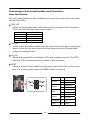
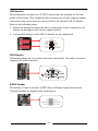
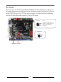
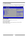
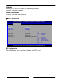
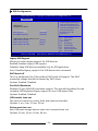
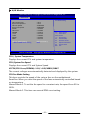
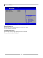
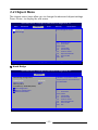
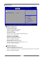
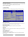
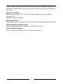
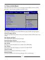
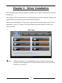
1
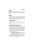
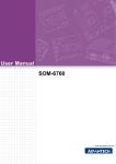
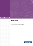
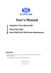
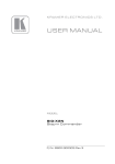
User’s Manual
Sapphire Pure White Fusion E350
AMD E350 Series Mainboard
TRADEMARK
All products and company names are trademarks or registered trademarks of
their respective holders.
These specifications are subject to change without notice.
Manual Revision 1.0
February 21, 2011
Federal Communications Commission (FCC) Statement
This device has been tested and found to comply with the limits for a Class B
digital device, pursuant to Part 15 of FCC Rules. These limits are designed to
provide reasonable protection against harmful interference in a residential
installation. This equipment generates, uses and can radiate radio frequency
energy and, if not installed and used in accordance with instructions contained
in this manual, may cause harmful interference to radio and television
communications. However, there is no guarantee that interference will not occur
in a particular installation.
If this product does cause harmful interference to radio or television reception,
which can be determined by turning the equipment off and on, the user is
encouraged to try to correct the interference by one or more of the following
measures:
y Reorient or relocate the receiving antenna.
y Increase the separation between the equipment and receiver.
y Connect the product into an outlet on a circuit different from that to which
the receiver is connected.
y Consult the dealer or an experienced radio/TV technician for help.
ÍNote1:
Connecting this device to peripheral devices that do not comply with Class
B requirements, or using an unshielded peripheral data cable, could also
result in harmful interference to radio or television reception
Note2: The user is cautioned that any changes or modifications not expressly
approved by the party responsible for compliance could void the user’s
authority to operate this product.
Note3: To ensure that the use of this product does not contribute to
interference, it is necessary to use shielded I/O cables
CE: Radiation of EN 55022 & Immunity of EN 55024
Waste Electrical and Electronic Equipment (WEEE) Statement
To protect the global environment, this product must be sent to separate collection
facilities for recovery and recycling.
DISPOSAL
Do not dispose of this product as unsorted municipal waste. Collect such
waste separately for special treatment.
~ ii ~
Table of Contents
Chapter 1 Introduction................................................................ 1
1-1 Mainboard Specifications ............................................................. 1
1-2 Package Contents ....................................................................... 3
1-3 Mainboard Layout ........................................................................ 4
Chapter 2 Installation .................................................................. 8
2-1 Before You Begin ....................................................................... 8
2-2 Installing the I/O Shield .............................................................. 8
2-3 Securing to the Chassis ............................................................. 8
2-4 Installing System Memory .......................................................... 9
Memory configurations ............................................................... 9
Memory Installation .................................................................... 9
2-5 Installing Expansion Cards ...................................................... 10
2-6 Connecting Cables .................................................................. 11
Connecting Power Supply Cables ............................................ 11
Connecting Serial ATA (SATA) Cables ...................................... 11
Connecting to the Internal Headers and Connectors ............... 12
Front Panel Header ............................................................ 12
USB Headers ...................................................................... 13
CFPA Header ...................................................................... 13
S/PDIF Header ................................................................... 13
Fan Headers ....................................................................... 14
2-7 Jumper Settings ....................................................................... 15
Chapter 3 Configuring the BIOS ................................................. 16
3-1 Enter BIOS Setup .................................................................... 16
3-2 Main Menu ............................................................................... 17
3-3 Advanced Menu ....................................................................... 18
PCI Subsystem Settings ............................................................ 19
ACPI Settings ........................................................................... 20
CPU Configuration ..................................................................... 21
IDE Configuration ..................................................................... 22
USB Configuration ................................................................... 23
~ iii ~
Super IO Configuration ............................................................. 24
H/W Monitor ............................................................................. 25
Onboard Device ....................................................................... 26
3-4 Chipset Menu ........................................................................... 27
North Bridge ............................................................................. 27
3-5 Boot Menu ............................................................................... 30
3-6 Security Menu .......................................................................... 32
3-7 Save & Exit Menu .................................................................... 33
Chapter 4 Driver Installation ........................................................ 35
~ iv ~
Chapter 1 Introduction
1-1 Mainboard Specifications
APU
¾ AMD® dual-core processor E350
Chip
¾ AMD® Hudson-M1 (A50M) Chip
Graphics
¾ ATD RadeonTM HD6310 GPU
¾ Three independent displays supporting concurrent display of either two
combination of HDMI, DVI and VGA
Port
VGA
Supported resolution
2560x1600@60MHz & 30bpp
DVI-D
1920x1080@60MHz & 36bpp
HDMI
1920x1080@60MHz & 24bpp (HDMI 1.3b)
System Memory
¾ Two 240-pin DDR3 SDRAM DIMM sockets
¾ Supports 1.5v DDR3-800/1066 DIMMs with single channel architecture
¾ Supports x16 and x8 DIMMs, non-ECC, unbuffered DIMMs
¾ Supports up to 8GB system memory
USB Ports
¾ Eight USB 2.0 ports (four at rear panel, four onboard headers), supporting
transfer speed up to 480Mbps
¾ Supports wake-up from S3 mode
SATA Ports
¾ Four SATA3 ports with 6Gb/s data transfer rate
¾ Supports AHCI (Advanced Host Controller Interface)
Onboard LAN
¾ One Gigabit Ethernet from Marvell 88E8059 Gigabit controller
~1~
Onboard Audio
¾ Supports 6-channel High-Definition audio
¾ Supports Jack-detection function
Expansion Slots
¾ One PCI-Express 2.0 x16 connector, supports x4 bandwidth, for VGA card use
only.
I/O
¾ Onboard Fintek F71808E LPC bus I/O controller
BIOS
¾ 16Mb SPI Flash with AMI based BIOS
¾ Supports ACPI (Advanced Configuration and Power Interface)
Form Factor
¾ Mini-ITX form factor of 170mm x 170mm
Operating systems:
¾ Supports Windows Vista and Windows 7
~2~
1-2 Package Contents
Your Sapphire mainboard comes with the following accessories.
1. Mainboard
2. Quick Installation Guide
3. Driver CD
4. I/O Shield
5. SATA Data Cable *2
~3~
1-3 Mainboard Layout
The following figure shows the location of components on the mainboard.
following page for description.
~4~
See
Item
Component description
1
AMD E350 APU with Cooler
2
AMD Hudson-M1 (A50M) Chip with Heatsink
3
DDR3 DIMM Slots 1-2
4
PCI-E x16 Slot (supports x4 bandwidth)
5
24-Pin ATX Power Connector
6
4-pin ATX_12V Power Connector
7
Mainboard Battery
8
PC Speaker
9
SATA3 Connectors *4
10
USB 2.0 Headers *4
11
Front Panel Header
12
S/PDIF Header
13
Front Panel Audio Header
14
CPU Fan Header
15
Power Fan Header
16
Clear CMOS Jumper
17
16Mb SPI Flash
18
Back Panel Connectors (see next page for detail)
~5~
I/O Back Panel
The I/O back panel for this mainboard is shown below. When installing the
mainboard into the computer case, use the bundled I/O shield to protect this
back panel.
1.
USB 2.0 Ports (Four)
The mainboard provides an OHCI (Open Host Controller Interface) Universal
Serial Bus root for attaching USB devices such as a keyboard, mouse or
other USB-compatible devices. Supports data transfer rates up to 480Mb/s.
2.
D-Sub VGA Port
The D-Sub VGA female port provides connection to analogue VGA
monitors.
3.
LAN Ports with LEDs
The mainboard provides one standard RJ-45 jack for connecting to a Local
Area Network (LAN). Two LEDs are built into the RJ-45 LAN connector.
These LEDs indicate the status of the LAN.
LED
LED Color
LED state
Off
A
B
4.
Green
Indicates
LAN link is not established
On
LAN link is established
Blinking
LAN activity is occurring
N/A
Off
10 Mb/s data rate
Green
On
100 Mb/s data rate
Yellow
On
1000 Mb/s data rate
DVI-D Port
The DVI-D (Digital Visual Interface-Digital) port provides a high-speed
digital interconnection between the computer and its display device.
Connect a monitor that supports DVI-D connection to this port. The DVI-D
port does not support analogue VGA monitors using a passive DVI to VGA
adapter.
~6~
5.
HDMI Port
The HDMI (High-Definition Multimedia Interface) provides an all-digital
audio/video interface to transmit the uncompressed audio/video signals
and is HDCP compliant. Connect the HDMI audio/video device to this port.
Dual Display Configurations:
This mainboard provides three ports for video output: D-Sub, DVI-D and
HDMI. Please refer to table below for dual display configurations supported.
Supported configurations
D-Sub + DVI-D
DVI-D + HDMI
D-Sub + HDMI
6.
Audio Ports
This mainboard provides 2, or 6 channel audio. It is easy to differentiate
between the audio functions by referring to the color of the jacks.
Ports
Blue
2 channel
6 channel
Line-In
Line-In
Lime
Line-Out
Front Stereo-Out
Pink
Min-In
Min-In
~7~
Chapter 2 Installation
2-1 Before You Begin
Please take note of all precautions before you install anything on to the
mainboard or change any of the mainboard settings.
Turn off the power to your system and discharge your body’s static electric
charge by touching a grounded surface—for example, the metal surface of the
power supply—before performing any hardware procedure.
The manufacturer assumes no liability for any damage, caused directly or
indirectly, by improper installation of any components by unauthorized service
personnel. If you do not feel comfortable performing the installation, consult a
qualified computer technician.
Damage to system components, the mainboard, and injury to you may result if
power is applied during installation.
2-2 Installing the I/O Shield
The mainboard comes complete with an I/O shield. When installed in the chassis,
the shield blocks radio frequency transmissions, protects internal components
from dust and foreign objects, and promotes correct airflow within the chassis.
Install the I/O shield before installing the mainboard in the chassis. Place the
shield inside the chassis. Press the shield into place so that it fits tightly and
securely. If the shield does not fit, obtain a properly sized shield from the chassis
supplier.
2-3 Securing to the Chassis
When installing the mainboard, you have to secure the mainboard into the
chassis by fastening with nine screws. Please refer to your chassis manual for
instructions on installing.
~8~
2-4 Installing System Memory
This mainboard has two 240-pin DIMM sockets for DDR3 memory.
y
Supports 1GB, 2GB and 4GB DDR3 DIMMs.
y
Supports 1.5v DDR3-1066/800 DIMMs with single channel architecture.
Memory configurations
To use 1 DIMM: Install into either DIMM slot 1 or slot 2.
To use 2 DIMMs: Install into DIMM slot 1 and DIMM slot 2.
DIMM#2
DIMM#1
Memory Installation
DDR3 and DDR2 memory modules are physically different. Please only install
DDR3 DIMMs in this mainboard.
To make sure you have the correct DIMM, check that all the notches line up with
the DDR3 DIMM slot.
To install the DIMM, follow these steps:
1.
Pull clips on either side of the slot outwards. Align the DIMM module with
the slot.
2.
Press modules straight down until the plastic clips close and the module fits
tightly into the DIMM slot. Push clips inwards to make sure they are in
place.
~9~
2-5 Installing Expansion Cards
The mainboard provides one PCI Express 2.0 x16 slot.
PE1
PCI-E2.0 x16 slot (with x4 link, Blue)
PCI-E Slot
The design of this motherboard supports PCI-E Express x16 card complying with
the PCI Express specification.
ÍNote:
This PCI-Express x16 slot only supports x4 bandwidth and is intended
only for graphics card use.
To install a PCI Express card:
1.
Place the card in the PCI Express slot and press down on the card until it is
completely seated in the slot. If the card is not seated properly, it could
cause a short across the pins.
2.
Secure the card’s metal bracket to the chassis back panel with a screw.
~ 10 ~
2-6 Connecting Cables
This section takes you through all the necessary connections on the mainboard.
Connecting Power Supply Cables
y
24-pin ATX Power
PW2 is the main power supply connector. Make sure that the power supply
cable pins are properly aligned with the connector on the mainboard. Firmly
plug the power supply cable into the connector and make sure it is secure.
ÍNote: If you’d like to use 20-pin ATX power supply, please plug in your power supply
cable aligned with pins 1 & 13. The 24-pin main power connector is
backwardly compatible with ATX power supplies with 20-pin connectors.
y
4-pin ATX 12V Power
PW12, a 4-pin ATX 12V power connector, is used to provide power to the CPU.
Align the power plug to the connector and press firmly until seated.
24-pin ATX Power connector
4-pin ATX Power connector
Connecting Serial ATA (SATA) Cables
SATA cables support Serial ATA protocol. Each cable can be used to connect one
internal SATA drive to mainboard.
The SATA0 ~SATA3 connectors operate at a speed up to 6Gb/s.
SATA3
Attach one end of the SATA cable
to one of the SATA connectors on
the board and attach the other
end of the cable to the SATA drive
SATA2
SATA1
SATA0
~ 11 ~
Connecting to the Internal Headers and Connectors
Front Panel Header
The front panel header on this motherboard is used to connect the front panel
switches and LEDs.
PWR_LED
Attach the front panel power LED cable to these two pins of the connector.
The Power LED indicates the system’s status.
System Status
On
Off
S3
S4
Power LED indicates
The LED is on
The LED is off
The LED will blink
The LED is off
PW_ON
Attach the power button cable from the case to these two pins. Pressing the
power button on the front panel turns the system on and off rather than
using the onboard button.
HD_LED
Attach the hard disk drive indicator LED cable to these two pins. The HDD
indicator LED indicates the activity status of the hard disks.
RESET
Attach the Reset switch cable from the front panel of the case to these two
pins. The system restarts when the RESET switch is pressed.
Header
HD_LED
PWRLED
RESET
PWRSW
~ 12 ~
Pin
1
Signal
HD_PWR
3
HD Active
2
PWR LED+
4
PWR LED-
5
Ground
7
RST BTN
6
PWR BTN
8
Ground
No Connect
9
+5V
Empty
10
Empty
USB Headers
This mainboard contains four (4) USB 2.0 ports that are exposed on the rear
panel of the chassis. This mainboard also contains two 10-pin onboard header
connectors that can be used to connect to four (4) external USB 2.0 devices.
Refer to the following steps:
1. Secure the bracket to either the front or rear panel of your chassis (not all
chassis are equipped with the front panel option).
2. Connect the cable(s) to the USB 2.0 header on the mainboard.
1
2
V CC
US B 0-
US B 1-
US B 0+
US B 1+
Ground
E mpt y
Ground
No Connect
CFPA Header
This header allows you to connect the front panel audio. The audio connector
supports HD audio standard.
S/PDIF Header
This header is used to connect S/PDIF (Sony & Philips Digital Interconnect
Format) interface for digital audio transmission.
~ 13 ~
Fan Headers
There are two fan headers (CPUFAN, PWRFAN) on the motherboard. They can
be speed-detected and displayed in the Hardware Health Configuration section
of the CMOS Setup. Only CPU fan can be speed-controlled and automatically
turned off after the system enters S3, S4 or S5 mode.
CPUFAN
Note:
The CPU fan cable is a 3-pin
connector. Connect the 3-pin
cable to the mainboard
connector.
PWRFAN
PWRFAN CPUFAN
~ 14 ~
2-7 Jumper Settings
If the CMOS data becomes corrupted or you forgot the supervisor or user
password, clear the CMOS data to reconfigure the system back to the default
values stored in the ROM BIOS.
To clear CMOS data, please follow the steps below.
1. Turn off the system.
2. Change the jumper from “1-2” to “2-3” position
for a few seconds.
3. Replace the jumper back to the “1-2” position.
4. Turn on the system and hold down the <Del> key
to enter BIOS Setup.
~ 15 ~
Chapter 3 Configuring the BIOS
This chapter provides information on the BIOS Setup program and allows you to
configure the system for optimum use.
3-1 Enter BIOS Setup
The BIOS is the communication bridge between hardware and software.
Correctly setting the BIOS parameters is critical to maintain optimal system
performance.
Use the following procedure to change BIOS settings.
1.
Power on the computer.
2.
Press the Del key when the following message briefly shows upon the
bottom of the display during Power On Self Test (POST).
Press F1 to continue, DEL to enter Setup.
Pressing Del takes you to the BIOS Aptio Setup Utility.
ÍNote1:
It is strongly recommended that you do not change the default BIOS
settings. Changing some settings could damage your computer.
ÍNote2:
The BIOS options in this manual are for reference only. BIOS screens
in manuals are usually the first BIOS version when the board is
released and may be different from your purchased motherboard.
Users are welcome to download the latest BIOS version from our
official website
ControlKeys
Please check the following table for the function description of each Controlkey.
Control Key(s)
Å/Æ
Ç/È
+/<Enter>
<F1>
<F2>
<F3>
<F4>
<ESC>
Function Description
Moves cursor left or right to select Screens
Moves cursor up or down to select items
To change option for the selected items
To bring up the selected screen
To display the General Help Screen
To load previous values for all the settings
To load optimal default values for all the settings
To save changes and exit the SETUP UTILITY
To jump to the Exit Screen or exit the current screen
~ 16 ~
3-2 Main Menu
When entering the Aptio Setup Utility, the main menu screen appears. This main
menu includes the system overview and displays the basic system configuration,
such as BIOS information, memory size and system date/time.
Aptio Setup Utility - Copyright (C) 2010 American Megatrends, Inc.
Advanced
Main
Chipset
Boot
BIOS Information
BIOS Vendor
Core Version
Compliency
Project Version
Build Date and Time
American Megatrends
4.6.4.0
UEFI 2.1
1A0VQ 0.22 x64
02/15/2011 11: 45:58
Memory Information
Total Memory
4080 MB (DDR3)
System Date
System Time
[Wed 02/16/2011]
[13:55:02]
Access Level
Administrator
Version 2.10.1208.
Security
Save & Exit
Set the Date. Use Tab to
switch between Data
elements.
ÆÅ:
Select Screen
: Select Item
Enter: Select
+/-: Change Opt.
F1: General Help
F2: Previous Values
F3: Optimized Defaults
F4: Save and Exit
ESC: Exit
Copyright (C) 2010 American Megatrends, Inc.
BIOS Information
This field displays the current BIOS version, build date and ID information etc..
Memory Information
Displays current system memory size.
System Date
Allows you to set the system date.The format is <Day><Month><Date><Year>.
[Day]
Weekday from Sun. to Sat., this is automatically displayed by BIOS.
[Month] The month from 1 to 12.
[Date]
The date from 1 to 31 can be keyed by numeric function keys.
[Year]
The year can be adjusted by users.
System Time
Allows you to set the system time. The time format is
<hour>:<minute>:<second>.
Access Level
Displays the current user's access level.
~ 17 ~
3-3 Advanced Menu
The Advanced menu items allow you to change the settings for the CPU, USB
and other system devices. Press <Enter> to display the configuration options.
Aptio Setup Utility - Copyright (C) 2010 American Megatrends, Inc.
Main
Advanced
Legacy OpROM Support
Launch PXE OpROM
Launch Storage OpROM
Chipset
Boot
Save & Exit
Enables or disable Boot
option for legacy network
devices
[Disabled]
[Enabled]
PCI Subsystem Settings
ACPI Settings
CPU Configuration
IDE Configuration
USB Configuration
Super IO Configuration
H/W Monitor
Onboard Device
Version 2.10.1208.
Security
ÆÅ:
Select Screen
: Select Item
Enter: Select
+/-: Change Opt.
F1: General Help
F2: Previous Values
F3: Optimized Defaults
F4: Save and Exit
ESC: Exit
Copyright (C) 2010 American Megatrends, Inc.
Launch PXE OpROM
Enables the Boot option for legacy network devices.
Options: Enabled, Disabled.
Launch Storage OpROM
Enables the Boot option for mass storage devices with option ROM.
Options: Enabled, Disabled.
~ 18 ~
PCI Subsystem Settings
Aptio Setup Utility - Copyright (C) 2010 American Megatrends, Inc.
Advanced
PCI Bus Driver Version
PCI Express Device Settings
Relaxed Ordering
Extended Tag
No Snoop
Maximum Payload
Maximum Read Request
V2.03.00
Enables or Disables PCI Express
Device Relaxed ordering.
[Disabled]
[Disabled]
[Enabled]
[Auto]
[Auto]
PCI Express Link Settings
ASPM Support
[Disabled]
WARNING: Enabling ASPM may cause some
PCI-E devices to fail
Extended Synch
[Disabled]
Version 2.10.1208.
ÆÅ:
Select Screen
: Select Item
Enter: Select
+/-: Change Opt.
F1: General Help
F2: Previous Values
F3: Optimized Defaults
F4: Save and Exit
ESC: Exit
Copyright (C) 2010 American Megatrends, Inc.
Relaxed Ordering
Enables the PCI Express device Relaxed Ordering.
Options: Enabled, Disabled.
Extended Tag
Allows device to use 8-bit TAG field as a requester.
Options: Enabled, Disabled
No Snoop
Enables the No Snoop function of PCI Express device.
Options: Enabled, Disabled.
Maximum Payload
Sets the Maximum Payload size of PCI Express Device or allows the System BIOS
to select the value.
Options: Auto, 128 Bytes, 256 Bytes, 512 Bytes, 1024 Bytes, 2048 Bytes, 4096
Bytes.
Maximum Read Request
Sets the Maximum Read Request of PCI Express Device or allows the System
BIOS to select the value.
Options: Auto, 128 Bytes, 256 Bytes, 512 Bytes, 1024 Bytes, 2048 Bytes, 4096
Bytes.
~ 19 ~
ASPM Support
Sets the ASPM level, select “Force L0” can force all links to L0 state.
Options: Disabled, Auto, Force L0.
Extended Synch
If select “Enabled”, allows generation of Extended Synchronization patterns.
Options: Enabled, Disabled.
ACPI Settings
Aptio Setup Utility - Copyright (C) 2010 American Megatrends, Inc.
Advanced
Enable ACPI Auto Configuration
[Disabled]
Enable Hibernation
ACPI Sleep State
Lock Legacy Resources
[Enabled]
[S3 (Suspend to RAM)]
[Disabled]
Enables or Disables BIOS
ACPI Auto Configuration.
ÆÅ:
Select Screen
: Select Item
Enter: Select
+/-: Change Opt.
F1: General Help
F2: Previous Values
F3: Optimized Defaults
F4: Save and Exit
ESC: Exit
Version 2.10.1208.
Copyright (C) 2010 American Megatrends, Inc.
Enable ACPI Auto Configuration
Enables the BIOS ACPI auto configuration.
Options: Enabled, Disabled.
Enable Hibernation
Enables system ability to Hibernate (OS/S4 Sleep Sate). This option may be not
effective with some OS.
Options: Enabled, Disabled.
ACPI Sleep State
Selects the ACPI state used to suspend system.
Options: Suspend Disabled, S3 (Suspend to RAM).
Lock Legacy Resources
When enabled (locked), this option prevents the operating system from
modifying assignments for legacy resources.
Options: Enabled, Disabled.
~ 20 ~
CPU Configuration
Aptio Setup Utility - Copyright (C) 2010 American Megatrends, Inc.
Advanced
CPU Configuration
Limit CPUID Maximum
PSS Support
PSTATE Adjustment
PPC Adjustment
NX Mode
SVM Mode
C6 Mode
Node 0 Information
Version 2.10.1208.
Disabled for Windows XP.
[Disabled]
[Enabled]
[PState 0]
[PState 0]
[Enabled]
[Enabled]
[Enabled]
ÆÅ:
Select Screen
: Select Item
Enter: Select
+/-: Change Opt.
F1: General Help
F2: Previous Values
F3: Optimized Defaults
F4: Save and Exit
ESC: Exit
Copyright (C) 2010 American Megatrends, Inc.
Max CPUID Value Limit
We recommend leaving it disabled, unless you are using a very old OS or
experiencing problems related to CPU identification/compatibility.
Options: Enabled, Disabled.
PSS Support
Enables the generation of ACPI_PCC,_PSS, and _PCT object.
Options: Enabled, Disabled.
PSTATE Adjustment
This item allows you to adjust startup P-State level.
Options: PState 0 ~7.
PPC Adjustment
This item allows you to adjust _PPC object.
Options: PState 0 ~2
NX Mode
Enables the No-execute page protection function.
Options: Enabled, Disabled.
SVM Mode
Enables the CPU SVM( Secure Virtual Machine) function.
Options: Enabled, Disabled.
~ 21 ~
C6 Mode
Allows you to select C6 State for Nehalem processor.
Options: Enabled, Disabled.
Node 0 Information
Displays the Node 0 Information.
IDE Configuration
Aptio Setup Utility - Copyright (C) 2010 American Megatrends, Inc.
Advanced
IDE Configuration
SATA Port0
SATA Port1
SATA Port2
SATA Port3
[Enabled]
[Enabled]
[Enabled]
[Enabled]
SATA Port0
SATA Port1
SATA Port2
SATA Port3
ST3320613AS
Not Present
Not Present
PIONEER DVD-RW ATAPI
Version 2.10.1208.
ÆÅ:
Select Screen
: Select Item
Enter: Select
+/-: Change Opt.
F1: General Help
F2: Previous Values
F3: Optimized Defaults
F4: Save and Exit
ESC: Exit
Copyright (C) 2010 American Megatrends, Inc.
IDE Configuration
This filed allows you to enable or disable the SATA port.
~ 22 ~
USB Configuration
Aptio Setup Utility - Copyright (C) 2010 American Megatrends, Inc.
Advanced
USB Configuration
USB Devices:
1 Keyboard, 1 Mouse
Legacy USB Support
EHCI Hand-off
Part 60/64 Emulation
[Enabled]
[Disabled]
[Enabled]
ÆÅ:
Select Screen
: Select Item
Enter: Select
+/-: Change Opt.
F1: General Help
F2: Previous Values
F3: Optimized Defaults
F4: Save and Exit
USB Hardware delays and time-outs:
USB transfer time-out
[20 sec]
Device reset time-out
[20 sec]
Device power-up delay
[Auto]
Version 2.10.1208.
Enables Legacy USB support;
AUTO option disables legacy
support if no USB devices are
connected, DISABLED option
will keep USB devices
available only for EFI
application.
Copyright (C) 2010 American Megatrends, Inc.
Legacy USB Support
Allows you select legacy support for USB devices.
Enabled: Enables Legacy USB support.
Disabled: Keep USB devices available only for EFI application.
Auto: Disables legacy support if no USB devices are connected.
EHCI Hand-off
This is a workaround for OSes without EHCI hand-off support. The EHCI
ownership change should be claimed by EHCI driver.
Options: Enabled, Disabled.
Part 60/64 Emulation
Enables I/O port 60h/64h emulation support. This should be enabled for the
complete USB keyboard legacy support for non-USB aware OSes.
Options: Enabled, Disabled.
USB transfer time-out
The time-out value for control, bulk, and interrupt transfers.
Options: 1 sec, 5 sec, 10 sec, 20 sec.
Device reset time-out
Sets USB mass storage devices start unit command time-out.
Options: 10 sec, 20 sec, 30 sec, 40 sec.
~ 23 ~
Device power-up delay
Maximum time the device will take before it properly reports itself to the Host
controller. ‘Auto’ uses default values; for a Root port it is 100ms, for a Hub port
the delay is taken from Hub descriptor.
Options: Auto, Manual.
Super IO Configuration
Aptio Setup Utility - Copyright (C) 2010 American Megatrends, Inc.
Advanced
Super IO Configuration
Super IO Chip
Restore on AC Power Loss
EuP Function
Fintek F71808
[Always Off]
[Disabled]
ÆÅ:
Select Screen
: Select Item
Enter: Select
+/-: Change Opt.
F1: General Help
F2: Previous Values
F3: Optimized Defaults
F4: Save and Exit
ESC: Exit
Version 2.10.1208.
Copyright (C) 2010 American Megatrends, Inc.
Restore on AC Power Loss
Enables your computer to automatically restart or return to its last operating
status after power returns from a power failure.
Options: Always off, Always on, Last State.
EuP Function
Enables the EuP (Energy Using Products) function, allows BIOS to switch off
some power at S5 state to get system ready for the EuP requirement to reduce
power consumption.
Options: Enabled, Disabled.
~ 24 ~
H/W Monitor
Aptio Setup Utility - Copyright (C) 2010 American Megatrends, Inc.
Advanced
PC Health Status
Fan Mode Setting.
CPU Temperature
System Temperature
CPU Fan Speed
System Fan Speed
VCC3V
CPU Vcore
VDIMM
+1.1V
+1.8V
VSB3V
VBAT
: +45 C
: +32 C
: 4500 RPM
: 5000 RPM
: +3.296 V
: +1.368 V
: +1.520 V
: +1.112 V
: +1.808 V
: +3.296 V
: +3.312 V
CPU Fan Mode Setting
Manual RPM Count Setting
[Manual Mode 2]
4500
Version 2.10.1208.
ÆÅ:
Select Screen
: Select Item
Enter: Select
+/-: Change Opt.
F1: General Help
F2: Previous Values
F3: Optimized Defaults
F4: Save and Exit
ESC: Exit
Copyright (C) 2010 American Megatrends, Inc.
CPU / System Temperature
Displays the current CPU and system temperature.
CPU /System Fan Speed
Displays the current CPU and System Speed
VCC3V/CPU Vcore/VDIMM/+1.1V/+1.8V/VSB3V/VBAT
The current voltages are automatically detected and displayed by the system.
CPU Fan Mode Setting
This item controls the speed of the various fans on the motherboard.
SmartFan: When you want the speed of the fans automatically controlled based
on temperature.
Manual Mode 1: To set the fan speed to a constant rate, the speed from 0% to
100%.
Manual Mode 2: This item can manual RPM count setting.
~ 25 ~
Onboard Device
Aptio Setup Utility - Copyright (C) 2010 American Megatrends, Inc.
Advanced
Marvell Gigabit Lan
HD Audio Azalia Device
[Enabled]
[Enabled]
ÆÅ:
Select Screen
: Select Item
Enter: Select
+/-: Change Opt.
F1: General Help
F2: Previous Values
F3: Optimized Defaults
F4: Save and Exit
ESC: Exit
Version 2.10.1208.
Copyright (C) 2010 American Megatrends, Inc.
Marvell Gigabit Lan
Enables the onboard Marvell GigaLan function for LAN.
Options: Enabled, Disabled
HD Audio Azalia Device
Enables the onboard High Definition Audio controller.
Options: Auto, Enabled, Disabled.
~ 26 ~
3-4 Chipset Menu
The chipset menu items allow you to change the advanced chipset settings.
Press <Enter> to display the sub-menu.
Aptio Setup Utility - Copyright (C) 2010 American Megatrends, Inc.
Main
Advanced
Boot
Chipset
Boot
North Bridge
South Bridge
Security
Save & Exit
North Bridge Parameters
ÆÅ:
Select Screen
: Select Item
Enter: Select
+/-: Change Opt.
F1: General Help
F2: Previous Values
F3: Optimized Defaults
F4: Save and Exit
ESC: Exit
Version 2.10.1208.
Copyright (C) 2010 American Megatrends, Inc.
North Bridge
Aptio Setup Utility - Copyright (C) 2010 American Megatrends, Inc.
Security
Chipset
North Bridge Configuration
IOMMU Mode
Memory Clock
Memory Clock
Total Memory: 4080 MB (DDR3)
GFX Configuration
Memory Configuration
Node 0 Information
Version 2.10.1208.
IOMMU is supported on LINUX
based system to convert 32bit I/O
to 64bit MMIO.
[Disabled]
[Auto]
533
ÆÅ:
Select Screen
: Select Item
Enter: Select
+/-: Change Opt.
F1: General Help
F2: Previous Values
F3: Optimized Defaults
F4: Save and Exit
ESC: Exit
Copyright (C) 2010 American Megatrends, Inc.
~ 27 ~
IOMMU Mode
IOMMU is supported on LINUX based system to convert 32bit I/O to 64bit
MMIO.
Options: Disabled, 32MB, 64MB, 128MB, 256MB, 512MB, 1GB, 2GB.
Memory Clock
Allows you to select different memory clock.
Options: Auto, 400MHz, 533MHz.
GFX Configuration
PSPP Policy
Allows you to select PCIE speed power policy.
Options: Disabled, Performance, Balanced-High, Balanced-Low, Power
Saving.
Memory Configuration
Integrated Graphics
Enables integrated graphics controller.
Options: Disabled, Auto, Force.
UMA Frame buffer Size
This item will only appear when “Integrated Graphics” item is set to
“Force” option. It controls the amount of system memory that is allocated
to the integrated graphics processor.
Options: 32M, 64M, 128M, 256M, 512M, 1G, 2G.
Bank Interleaving
Bank Interleaving is an important parameter for improving overclocking
capability of memory. It allows system to access multiple banks
simultaneously.
Options: Enabled, Disabled.
Node 0 Information
This filed displays the memory information related to Mode 0.
~ 28 ~
South Bridge
Aptio Setup Utility - Copyright (C) 2010 American Megatrends, Inc.
Security
Chipset
SB CIM Version :
SB SATA Configuration
SB USB Configuration
SB Clock Spread Spectrum
1.1.0.5
Options for SATA Configuration
[Disabled]
ÆÅ:
Select Screen
: Select Item
Enter: Select
+/-: Change Opt.
F1: General Help
F2: Previous Values
F3: Optimized Defaults
F4: Save and Exit
ESC: Exit
Version 2.10.1208.
Copyright (C) 2010 American Megatrends, Inc.
SB ATA Configuration
OnChip SATA Channel
Enables onboard SATA Channel.
Options: Enabled, Disabled.
OnChip SATA Type
Allows you to set the onboard Serial SATA type.
Options: AHCI, Legacy IDE.
SATA IDE Combined Mode
Enables onboard SATA Channel.
Options: Enabled, Disabled.
External SATA on Port 0/ 1/ 2/ 3
Enables onboard external SATA port 0/ 1/ 2/ 3.
Options: Enabled, Disabled.
SB USB Configuration
USB Device Wakeup From S3 or S4
Allows a USB keyboard device to wake-up the system from S3 or S4 state.
Options: Enabled, Disabled.
~ 29 ~
SB Clock Spread Spectrum
This setting is for Electromagnetic Compatibility (EMC) purposes. It reduces EMI
radiations by slightly staggering normally synchronous clocks.
Options: Enabled, Disabled.
3-5 Boot Menu
The Boot menu is used to configure the boot settings and the boot priority.
Aptio Setup Utility - Copyright (C) 2010 American Megatrends, Inc.
Main
Advanced
Chipset
Boot Configuration
Setup Prompt Timeout
Bootup NumLock State
Boot
Boot
Save & Exit
Number of seconds to wait for
setup activation key. 65535(0xFFFF)
means indefinite waiting.
1
[On]
Quiet Boot
[Enabled]
CSM16 Module Version
07.63
Option ROM Message
Interrupt 19 Capture
[Force BIOS]
[Disabled]
Boot Option Priorities
Boot Option #1
Boot Option #2
[P3: ST3250318AS..]
[P0: PIONEER DVD..]
CD/DVD ROM Drive BBS Priorities
Hard Drive BBS Priorities
Version 2.10.1208.
Security
ÆÅ:
Select Screen
: Select Item
Enter: Select
+/-: Change Opt.
F1: General Help
F2: Previous Values
F3: Optimized Defaults
F4: Save and Exit
Copyright (C) 2010 American Megatrends, Inc.
Setup Prompt Timeout
This is used to set an additional time the POST should wait for the operator to
press the key to enter setup. The time is entered in seconds.
Bootup NumLock State
Selects the state of the keyboard’s numlock function after POST.
Options: On, Off.
Quiet Boot
Displays normal POST message. Select disable to display Logo instead of POST
message.
Options: Enabled, Disabled.
Option ROM Message
Sets display mode for Option ROM.
Force BIOS: To force to a BIOS-compatible output. This will show the option
ROM messages.
~ 30 ~
Keep Current: To keep the current video mode. This will suppress option ROM
messages. Option ROMs requiring interactive inputs may not work properly in
this mode.
Interrupt 19 Capture
Allows specify if legacy PCI option ROMs are allowed to capture software
interrupt 19h.
Options: Enabled, Disabled.
Boot Option #1/#2
These options are used to form the boot order and are dynamically generated.
CD/DVD ROM Drive BBS Priorities
Allow configuring the boot order for CD/DVD ROM device.
Hard Drive BBS Priorities
Allow configuring the boot order for Hard Drive device.
~ 31 ~
3-6 Security Menu
The Security menu allows you to change the system security settings.
Aptio Setup Utility - Copyright (C) 2010 American Megatrends, Inc.
Main
Advanced
Chipset
Boot
Security
Password Description
Set setup Administrator Password.
If ONLY the Administrator’s password is set, then this only limits
access to Setup and is only asked for when entering Setup.
If ONLY the User’s password is set, then this is a power on password
and must be entered to boot or enter setup. In Setup the user will
have Administrator rights.
The password must be 3 to 20 characters long.
Administrator Password
User Password
Version 2.10.1208.
Save & Exit
ÆÅ:
Select Screen
: Select Item
Enter: Select
+/-: Change Opt.
F1: General Help
F2: Previous Values
F3: Optimized Defaults
F4: Save and Exit
ESC: Exit
Copyright (C) 2010 American Megatrends, Inc.
Administrator Password
If ONLY the Administrator’s password is set, then this only limits access to Setup
and is only asked for when entering Setup. The password must be 3 to 20
characters long.
User Password
If ONLY the User’s password is set, then this is a power on password and must
be entered to boot or enter setup. In Setup the user will have Administrator
rights. The password must be 3 to 20 characters long.
~ 32 ~
3-7 Save & Exit Menu
The Save & Exit menu allows you to load the optimal default values for BIOS,
and save or discard your changes to the BIOS items.
Aptio Setup Utility - Copyright (C) 2010 American Megatrends, Inc.
Main
Advanced
Chipset
Boot
Security
Save Changes and Exit
Discard Changes and Exit
Save Changes and Reset
Discard Changes and Reset
Save & Exit
Exit system setup after saving the
changes.
Save Options
Save Changes
Discard Changes
ÆÅ:
Select Screen
: Select Item
Enter: Select
+/-: Change Opt.
F1: General Help
F2: Previous Values
F3: Optimized Defaults
F4: Save and Exit
Restore Defaults
Save as User Defaults
Restore User Defaults
Boot Override
P3: ST3250318AS
P0: PIONEER DVD-RW DVR-218L
Version 2.10.1208.
Copyright (C) 2010 American Megatrends, Inc.
Save Changes and Exit
This saves the changes to the CMOS RAM and exits the BIOS Setup program.
Discard Changes and Exit
This exits the BIOS Setup without saving the changes made in BIOS Setup to the
CMOS.
Save Changes and Reset
This resets system after saving the changes.
Discard Changes and Reset
This resets system without saving the changes.
Save Option
Allows you to save the options you made to the CMOS RAM.
Save Change
Allows you to save the changes you made to the CMOS RAM.
Discard Changes
Allows you to discard the selections you made.
Restore Defaults
The restore defaults are the factory settings of this motherboard.
~ 33 ~
Save as User Defaults
This is used to save all current settings as user default. The current setup state
can later be restored using Restore User Defaults.
Restore User Defaults
This is used to restore all tokens to settings previously stored by Save as User
Defaults.
Boot Override
This group of functions includes a list, each of them corresponding to one
device within the boot order. Select a drive to immediately boot that device
regardless of the current boot order.
~ 34 ~
Chapter 4 Driver Installation
After the operating system has been installed, you need to install drivers for this
mainboard.
The support CD that came with the motherboard contains necessary drivers and
useful utilities that enhance the motherboard features.
Insert the bundled driver CD into your optical drive and the main menu will be
displayed on your PC screen. Click each item button and select the item you
want to install.
<Main Page>
ÍNote :
If Autorun function is not enabled in your computer, browse the
contents of the support CD to locate the file autorun.exe, and click
this file to run the CD.
~ 35 ~