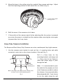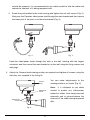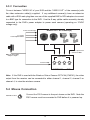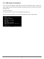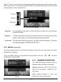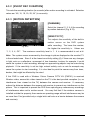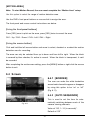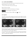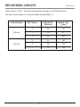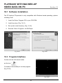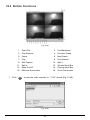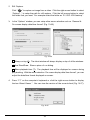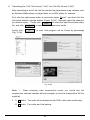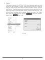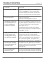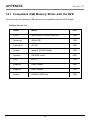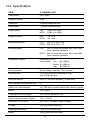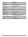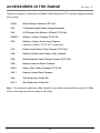
1
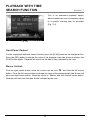
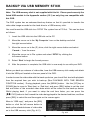
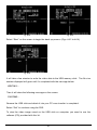
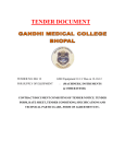
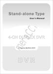
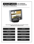
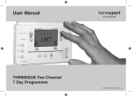
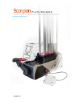
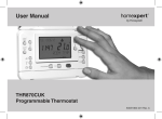
4 Camera Wired Coloured
CCTV Kit
CWK5
Installation and Operating Instructions
These instructions should be retained in a safe place for future reference.
CONTENTS
1 INTRODUCTION
2 KIT CONTENTS
4
3 DVR FEATURES
5
4.2
19
6.5.2 Account Setup
20
6.5.3 Password Setup
21
6.5.4 Clear Account Info
21
21
6.5.6 Time Set
22
Front Panel
6
4.1.1 DVR Button Functions
6
6.5.7 Event List
(Playback Feature)
22
6.6
Language
23
6.7
Logout
23
6.8
Exit
23
Rear Panel
8
9
5.1
Hard Disk Drive Installation
9
5.2
Monitor Connection
9
5.3
Camera Installation and
Connection
9
5.3.1 Installation
Dome Cameras
Heavy Duty Cameras
10
10
11
5.3.2 Connection
13
5.4
Mouse Connection
13
5.5
DVR Power Connection
14
6 SETUP
15
B. Set up using the Mouse
16
6.1
Camera
17
6.2
Record
17
6.2.1 [Record Framerate]
18
6.2.2 [Record Quality]
18
6.2.3 [Record Schedule]
18
Alarm (Optional)
19
6.3.1 [Buzzer Duration]
19
6.3.2 [Event REC Duration]
20
6.3.3 [Motion Detection]
20
Screen
21
6.4.1 [Border]
21
6.4.2 [Auto Sequence]
21
6.4.3 [Video Adjustment]
22
7 PLAYBACK WITH TIME
SEARCH FUNCTION
28
8 BACKUP VIA USB
MEMORY STICK
29
9 RECORDING LENGTH
31
10 PLAYBACK WITH BACKED-UP
VIDEO DATA ON PC
A. Set up using the DVR Front Panel 15
6.4
18
6
5 HARDWARE SETUP
6.3
System
6.5.1 Hard Disk Setup
6.5.5 Keypad Tone
4 PHYSICAL UNIT
4.1
6.5
3
2
32
10.1 Software Installation
32
10.2 Program Interface
32
10.3 Button Functions
33
11 TROUBLE SHOOTING
37
12 APPENDIX
38
12.1 Compatible USB Memory
Sticks with the DVR
38
12.2 Specification
39
13 ACCESSORIES IN
THE RANGE
42
14 DISPOSAL – RECYCLING
INSTRUCTIONS
43
15 GUARANTEE AND
CUSTOMER HELPLINE
44
INTRODUCTION
Section 1
The Response Wired Heavy Duty Cameras are colour, weatherproof day/night cameras.
The Response Wired Internal Dome Cameras are colour, day cameras. The cameras
easily connect to your DVR for the protection of your home or office, etc. The heavy duty
cameras are easily mounted on walls and the internal dome cameras on ceilings using the
supplied mounting brackets and bases.
The Response 4 Channel DVR provides a total video security solution for 4 channel digital
surveillance supporting duplex (simultaneous playback and record) functionality.
The DVR’s front panel buttons or mouse can operate all DVR menu settings.
Please read before you start:
Always use discretion when installing CCTV surveillance equipment especially
when there is perceived policy. Enquire regarding local regulations applicable
to the lawful installation of video recording / surveillance. Third party consent
may be required.
SAFETY AND INSTALLATION TIPS:
Do not attempt to open the units with the power adaptor plug connected to avoid any risk
of personal injury.
When installing CCTV camera(s), always follow manufacturer’s advice when using power
tools, steps, ladders, etc. and wear suitable protective equipment (e.g. safety goggles) when
drilling holes. Before drilling holes through walls or ceilings check for hidden electricity
cables and water pipes. The use of a cable/pipe detector is advisable.
When installing any cameras with this unit, it is advisable to use cable conduit to protect any
video / power extension cables from being exposed externally and to prevent/reduce the
chances of the cables being tampered with. After drilling any hole though an external wall
for a cable, ensure the hole is sealed up around the cable using a sealant to prevent drafts.
To prevent a fire or electrical shock hazard, do not attempt to open the housing of the
Heavy Duty Camera while the unit is exposed to rain, water or wet conditions. The Dome
Cameras should only be installed in dry internal conditions as they are not waterproof.
There are no user serviceable parts inside. Refer servicing to qualified service personnel.
NIGHT VISION:
The Cameras except for the dome models have built-in infra-red LEDs to allow you to
view at night for 24hrs surveillance. The LEDs will automatically activate at night and
the picture viewed will turn to black and white.
3
KIT CONTENTS
Section 2
1 x 4 Channel DVR unit
(with a 160GB hard drive unit fitted in the drawer)
2 x Wired Heavy Duty Colour Cameras
2 x Wired Internal Dome Colour Cameras
2 x 10m camera extension cable
2 x 20m camera extension cable
1 x Power adaptor and power cord
1 x 1 to 5 way power splitter cable assembly
1 x Video output to monitor cable (1m)
4 x Camera fixings kits - wall plugs and screws, Including allen key tool for
adjusting camera head position
For each heavy duty camera bracket: 4 x Ø 3.5mm x 27mm screws
and 4 x No.8, 28mm wall plugs
For each dome camera mounting base: 4 x Ø 3.5mm x 19mm screws
and 4 x No.7, 29mm ceiling plugs
1 x Optical mouse
1 x User manual
1 x PC driver CD for PC back up
(for Windows based operating systems only including Vista)
Keys for the hard drive drawer
4 x Window stickers
What you need to purchase:
USB memory stick if you require backing up recorded video on to a PC.
(See appendix for the only compatible USB stick models).
Tools Required:
Electric drill
5mm masonry drill bit
20mm masonry drill bit
No. 2 Philips screwdriver
3mm flat blade screwdriver
4
DVR FEATURES
Section 3
●
True duplex functionality: simultaneous play / record
●
PAL / NTSC operation
●
160GB installed hard drive unit
●
High quality colour Video at 50fps or 60fps recording / playback
●
Recording speed: PAL max. 50fps (quad); NTSC max. 60fps (quad)
●
Recording mode: continuous, motion detection, time schedule
●
123 hours continuous recording at 25fps with the 160GB hard drive.
(for only x 1 channel recording)
●
Recording and compressing video signal real time
●
With USB port for media backup via hard drive. Average 200KB/Sec
●
With motion detection and video loss alarm function
●
OSD: support multi-language
●
With power recovery auto-record function
5
PHYSICAL UNIT
Section 4
4.1 Front Panel
Channel
Buttons 1-4
Hard Drive Drawer
CH1
REW
CH1
PAUSE
CH1
PLAY
Quad Button
CH1
FWD
QUAD
STOP
UP
MENU
SEL
ESC
EDIT
REC
DOWN
PWR
Hard Drive
Drawer Lock
●
LED Lights
HDD
Rewind, Pause, Play,
Forward, Stop and
Record Buttons
Up/Down, SEL
Menu, ESC and
EDIT Buttons
LED Lights:
(a) GREEN (PWR): The DVR unit is powered up and running.
(b) RED (HDD):
●
System is recording or in playback mode.
Hard Drive Drawer Lock
4.1.1 DVR Button Functions:
A series of buttons on the DVR front panel allow the system to operate its basic functions,
such as recording, playback, fast-forward, reverse, etc. For more details about the DVR
menu, refer to “6. SETUP”.
– CH1
Use this button for full screen display of channel 1 on the monitor or move the cursor up.
– CH2
Use this button for full screen display of channel 2 on the monitor or move the cursor down.
– CH3
Use this button for full screen display of channel 3 on the monitor or move the cursor
left. Also you can press this button to reduce values when adjusting parameters.
– CH4
Use this button for full screen display of channel 4 on the monitor or move the cursor
right. Also you can press this button to increase values when adjusting parameters.
6
– Quad
Use this button for full screen display of all 4 video channels on the monitor screen.
If you push this button, the DVR will display all 4 channels (cameras) at the same time
in quad screen.
–
● (REC)
Press “REC” button to start manual recording. You will then see a red dot ‘ ● ’ on the
selected channel on the screen, which means that the channel is now recording. To
stop manual recording, press “REC” again during recording mode.
–
■ (STOP)
To stop playback, press the “STOP” button.
–
(PLAY)
After recording, press “PLAY” button to start video playback.
Playback will start with the oldest unread video data and then continue playing.
–
(FWD)
This is the fast forward button. To play the recorded stream faster, press the “FWD” button.
There are three levels of fast forward playback speed.
(a) FF1:
Play two times faster (x 2) than the normal play.
(b) FF2:
Play three times faster (x 3) than the normal play.
(c) FF3:
Play four times faster (x 4) than the normal play.
To change the fast forward play back speed level, press the “FWD” button again.
–
(REW)
This is the rewind button. To play the recorded stream backward, press the “REW” button.
Note: The fast forward and reverse playback speeds will vary depending on the frame
rate and record quality settings, as well as the number of channels recorded.
–
■■
(PAUSE)
To pause the video playback, press the “PAUSE” button. Then the video displaying will
be stopped. To continue playback, push the “PLAY” button.
– Menu
Displays menu option or will move to the previous screen.
7
– UP / DOWN
To change the menu field, use the up “ ” or down “ ” buttons.
– SEL
Use this button to change values on main menu or sub menu setting. Also use this button
to increase values when adjusting parameters.
4.2 Rear Panel
AC-DC Power
Adaptor Jack
Vent for Internal
Cooling Fan
PS/2
VIDEO OUTPUT
Video Output
●
CH1
CH2
CH3
CH4
Video Input - Channels 1-4
DC12V
PS/2 Mouse Port
USB Port
USB PORT
Use this port to backup video on to a USB stick for transferring on to a PC.
●
PS/2 MOUSE PORT
Use this port for PS/2 mouse connection.
●
VIDEO INPUT
Use these BNC ports (CH1 to CH4) to connect cameras to the DVR system. You will
need to use the supplied BNC to RCA adoptors when connecting a camera with a male
type RCA plug.
●
VIDEO OUTPUT
Use this port to connect the DVR to the monitor using the supplied 1m video output to
monitor cable.
●
AC-DC POWER ADAPTOR JACK
●
VENT FOR INTERNAL COOLING FAN
8
HARDWARE SETUP
Section 5
5.1 Hard Disk Drive Installation
Note: Only read if you wish to replace / upgrade the existing supplied 160GB hard
drive unit fitted in the DVR.
1.
Unlock the front hard drive drawer using the key supplied.
2.
Pull the drawers lever to remove the drawer from the DVR.
3.
Remove the x 4 screws on the base of the drawer which secure the hard drive
in place to remove the existing unit.
4.
Replace with the new hard drive unit, refit and lock the drawer again.
5.2 Monitor Connection
To display video images from the cameras
TV / MONITOR
on the monitor, the DVR’s video output
signal needs be transferred to your TV set
or monitor.
VIDEO
IN
Connect “VIDEO IN” of the monitor to
“VIDEO OUT” of the DVR system using the
supplied cable. Connect the BNC (male) end
Connect a monitor
to the "VIDEO OUT"
port on the DVR
VIDEO
OUT
to the DVR and the RCA (male) end to the
monitor end.
5.3 Camera Installation and Connection
Before drilling holes through walls or ceilings check for hidden electricity cables and water
pipes. The use of a cable/pipe detector is advisable. When installing the cameras, it is
advisable to use cable conduit to protect any video/power extension cables from being
exposed externally and to prevent/reduce the chances of the cables being tampered with.
Note: the extension cables for any camera can only be extended up to 30m in length due
to power loss.
9
5.3.1 Installation
Dome Cameras Installation
The Response Dome Camera is only suitable for internal use and should not be installed
outside. It is also recommended to install the extension cables for the dome camera in the
ceiling and passed down the wall through a cable conduit.
1.
Unscrew the rim part of the dome cover
from its base as shown below. Once the
cover is removed, take care not to touch
any of the exposed electronic circuitry to
avoid any possible damage to the
camera (Fig. 1).
2.
Use the base of the camera to mark out
the key hole mounting holes and the
Fig. 1.
cable connector’s hole on the ceiling.
Mounting Holes
Cable connectors
entry hole position
in ceiling
Fig. 2.
3
Drill 2 x 5mm holes for the mounting bracket’s ceiling plugs and 1 x 20mm hole for
the camera’s video and power plugs to pass through the ceiling.
4.
Once the cable hole and mounting holes have been made in the ceiling, feed the
connectors of the extension cables through the ceiling, the largest one first. The
camera is supplied fitted with a short piece of cable terminated with a video BNC
female plug and a female power plug. Connect the male end of the video BNC
plug and male power plug from the extension cable into the camera end. Push the
cables into the ceiling before mounting the base.
10
5.
Mount the base to the ceiling using the supplied fixing screws and plugs. Adjust
the tilt and panning positions of the camera lens as shown (Fig. 3).
Loosen screw to adjust
panning position
Fig. 3.
6.
Refit the cover of the camera on to its base.
7.
If the position of the camera needs further adjusting after the system is powered
up, ensure the power is isolated from the cameras when removing the cover again
to prevent the risk of any shock.
Heavy Duty Cameras Installation
The Response Wired Heavy Duty Cameras are colour, weatherproof day / night cameras.
1.
Use the cameras main bracket to mark out the x 4 mounting holes and cable
connector’s entry hole on the chosen location of the wall (Fig. 1).
Drill 4 x 5mm holes for the
mounting bracket’s wall plugs and
1 x 20mm hole for the Camera’s
video and power plugs to pass
through the wall.
4 x Camera
Mounting Holes
Note: It is recommended to pass
the cable into the property as close
Mark out the single cable entry hole in the central position
in relation to the 4 x Camera Mounting Holes
to the Camera as possible to reduce
the chances of any exposed cables
being tampered with. If you choose
Fig. 1.
to run the cable along the wall
11
outside the property, it is recommended to use cable conduit to hide the cable and
reduce the chances of it being tampered with.
2.
Screw the post bracket to the main housing and tighten the nut until secure (Fig. 2).
Now pass the Cameras video / power lead through the main bracket and then secure
the lower part of the post on to the main bracket (Fig. 3).
Fig. 2.
Fig. 3.
Feed the video/power leads through the hole in the wall, starting with the largest
connector, and then mount the main bracket on to the wall using the fixing screws and
wall plugs.
3.
Adjust the Camera head viewing position as required and tighten all screws using the
allen key tool supplied in the fixing kit.
Camera
Head
You can make adjustments to the
viewing positions as shown (Fig. 4).
Note:
Adjustment
Screw
It is advisable to use cable
conduit to protect any video/power
extension cables from being exposed
externally and to prevent/reduce the
chances of the cables being tampered
Adjustment
Screws
with.
Fig. 4.
12
5.3.2 Connection
Connect between “VIDEO IN” of your DVR and the “VIDEO OUT” of the camera(s) with
the video extension cable(s) supplied. If any additional camera(s) have an extension
cable with a RCA male plug then use one of the supplied BNC to RCA adaptors to convert
to a BNC type for connection to the DVR. Use the 5 way splitter cable assembly already
connected to the DVR’s power adaptor to power each camera (operating on 12VDC
voltage only).
"VIDEO OUT" on Camera(s)
Power to Camera(s)
1 to 5 way
Power Splitter Cable
Video outputs from
Camera to DVR
DVR's Power Supply
Adaptor output
VIDEO INPUT
Power to DVR
CH1
CH2
CH3
CH4
"VIDEO IN" on DVR
Note: If this DVR is used with the Wireless Colour Camera CCTV Kit (CWFK1), the video
output from the receiver can be connected to either channel 1, channel 2, channel 3 or
channel 4, to view the wireless camera.
5.4 Mouse Connection
PS/2 Mouse Port
Connect the PS/2 mouse to the port shown on the DVR. Note the
PS/2 mouse must be connected to DVR before it is powered up.
13
5.5 DVR Power Connection
Connect the power adaptor's output plug into the DVR to power the DVR. Connect the
power adaptor’s mains lead into the adaptor and plug into the main’s (240VAC) wall socket
and switch ON.
The DVR will boot up.
The screen shown in Fig. 5.01 will be displayed during boot up.
After the system has booted up, the DVR will display the monitor in quad mode.
Fig. 5.01
14
SETUP
Section 6
If you have just replaced the existing hard drive with a new hard drive on the system, it is
advised to format the hard drive first. Please refer to Section 6.5, pages 22- 23.
The system includes a login window, and
there are three password levels in the
system,
including
admin
(highest),
operator, and guest (lowest), Fig. 6.01.
Fig. 6.01
If the user does not login to the system,
the user can only view live video display. When the user is logged into the system,
and no operation is performed within 1 minute, the system will automatically logout.
A: Set up using the DVR Front Panel
After system has booted-up, press the “MENU” button on the DVR front panel and there will
be a login window. There is one factory-preset login “account / password” “admin /111111”
at admin level. The user can use it to login to the system for the first time.
After logging in to the system, press button “MENU” to make any changes of DVR
settings and you will see screen on the monitor as Fig 6.03 on page 16. Then press the
“UP” or “DOWN” key on the DVR front panel to move the cursor. Press the “SEL” button
in order to change the settings. In the MAIN MENU, the cursor “
“
will be shown on
the screen right next to each sub menu. To move to the previous screen again, press the
“MENU” button.
The system allows up to four user accounts. The administrator can set up the login name,
password and level for each user. The administrator can also add or delete users. (Please
refer to Section 6.5.2 for Account Setup on page 24.)
The admin can operate everything. The operator can operate anything except examining
user accounts, formatting the hard drive and modifying his password level. The guest can
operate live video display and video playback, or modify values that are independent of
the recording setup. If the user has no right to modify a value, an identifier “
appear on the top right corner of the screen.
15
” will
B: Set up using the Mouse
After the system has booted-up, click the
right mouse button and the login window
will appear. Move the cursor to “Account”,
and click the left mouse button and input
the correct account by moving the cursor
over the correct numbers/characters and
left clicking the mouse button to select
them.
Select “Password” and input the
correct password. Finally select “Login” to
Fig. 6.02
enter the system. There is one factorypreset
login
“account /
password”
“admin /111111” at admin level. The user can use it to login to the system for the first time.
Suggestive window options:
Channel 1 view
Channel 2 view
Channel 3 view
Channel 4 view
All channel view
Play record list
●
Manual recording or Stop manual recording
Menu option
Logout
Channel auto sequence. The icon “
” won’t display if the order of “auto
sequence” is “OFF”.
After the system has booted-up, click the
right mouse button and there will be
suggestive window options on the monitor
(Fig. 6.02). Select the icon “
will see the (
”. You
) screen on the monitor
(Fig. 6.03).
(Note: Please refer to Section 6.5.2 for
Account Setup on page 24.)
Fig. 6.03
Move the mouse up or down to move the cursor. Click the left mouse button to change the
settings. Click the right mouse button to go back to the previous screen.
16
6.1 Camera
Use this option for video colour adjustment for each channel (1, 2, 3, 4). Move to the
“Display” option to enable or disable the screen display of each camera. Modify the
camera name of each channel (Figs. 6.04 and 6.05).
Fig. 6.04
Fig. 6.05
6.2 Record
This section allows the user to set the DVR to record over timed periods and via motion
detection. (Note: If at any time you wish to start manually recording then press the
“REC ● ” button once on the DVR. Press again to stop recording manually).
Use the ‘Record’ option to setup the quality
of recording and the recording schedule
over the 24 hour period (Fig 6.06).
Fig. 6.06
17
6.2.1 [RECORD FRAMERATE]
Change the record frame rate for each
channel - see Fig. 6.07. The higher the
record frame rate, the more natural
movement you will see in playback.
Independent setting for each channel is
possible.
For PAL video output format, the system
Fig. 6.07
default value is 12 frames per second
with each channel, which means the system will record 48 frames per second with all
channels. The user can set frame rate as 3 ~ 25 frames per second with each channel.
The maximum value of total frames per second with all channels is 50 frames.
For NTSC video output format, the system default value is 15 frames per second with each
channel, which means the system will record 60 frames per second with all channels.
The user can set the frame rate as 3 ~ 30 frames per second with each channel. The
maximum value of total frames per second with all channels is 60 frames.
Press button [SEL] / [CH4] or click the left mouse button to select icon “ ” to increase the
record frame rate for each channel. Press button [CH3] or click the left mouse button on
the icon “ ” to decrease the record frame rate for each channel.
Note: If you set the record frame rate to off, the channel won’t record.
6.2.2 [RECORD QUALITY]
Choose the recording quality from 1 / 2 / 3. The highest recording quality is 3, and the
lowest recording quality is 1. The higher the recording quality is, the higher the video
image quality is during playback. The higher the quality, the more hard disk space will be
consumed. Record frame rate, recording quality and hard disk space will affect the total
recording time of the DVR system.
6.2.3 [RECORD SCHEDULE]
Note: To start motion record, make sure the period that you intend to record is “
” in
the “record schedule” menu. (Green bar - see Fig. 6.08 overpage).
Press button [Up] / [Down] or move the mouse to move the desired time block, then press
[SEL] or click the left mouse button to adjust the video recording method for each time
18
period. The user can select the same record method for the whole 24 hr period in one go.
Move the cursor to 24 and press [QUAD] button in the DVR front panel, or left click the
mouse button on the time period 24.
Grey bar
Red bar
Green bar
Fig. 6.08
- Grey bar:
No recording will be made for this time period unless the user activates
manual recording.
- Red bar:
The time period with a red bar will activate continuous recording mode (Time
record) unless there is any manual stopping during that period.
- Green bar: The time period with a green bar is for built-in motion recording. (See also
the following chapter “MOTION DETECTION”).
6.3 Alarm
(Optional)
An internal buzzer built in the DVR will activate to alert the user that motion has been
detected by a Camera.
Press the [SEL] button or using the left mouse button, click icon “ ” / “ ”, to adjust
parameters of each option.
6.3.1 [BUZZER DURATION]
This sets the buzzer duration time (in
seconds) after an alarm is activated.
Selection values are “05, 10, 15, 20, 25, 30,
cont, off” (in seconds).
Default at “off”
(Fig. 6.09).
When “buzzer duration” is “cont”, the
buzzer will sound continuously.
Fig. 6.09
19
6.3.2 [EVENT REC DURATION]
This sets the recording duration (in seconds) after motion recording is activated. Selection
values are “ 05, 10, 15, 20, 25, 30 ” (in seconds).
6.3.3 [MOTION DETECTION]
[CHANNEL]
Select the channel (1, 2, 3, 4) for recording
by motion detection (Fig. 6.10).
[SENSITIVITY]
This adjusts the sensitivity of the built-in
motion sensor on the DVR system
while recording. The lower the number,
Fig. 6.10
the higher the sensitivity is. Values are
“1, 2, 3, 4, Off ”. The maximum sensitivity level is 1. It is recommended to set at 4.
Note: The system senses movement by the change in picture displayed on the monitor / TV
in the selected area. Even if at the lowest sensitivity setting (4), if there are any changes
in light such as a reflections, movement of tree branches, bushes for example, it could
cause the system to start recording, although no approaching objects may be seen during
playback. If the sensitivity is set too high, natural activity such as rain for example may
cause the system to start recording. It is also ideal to point the camera way from trees,
bushes, that might be affected by the wind.
If this DVR is used with a Wireless Colour Camera CCTV Kit (CWFK1) to received
Wireless video, ensure this video viewed on the TV is the best possible reception (i.e, no
interference lines viewed on the TV) between the camera and receiver. If necessary
reduce the distance between the camera and receiver to prevent any interference on the
picture. This is important to prevent the DVR from capturing any unnecessary recordings
of interference when set to motion record. You may find that if the wireless camera is
installed outside the property, then maximum operating range without interference may be
no more than 10m (provided only a single brick wall acts as a barrier between the camera
and receiver).
20
[MOTION AREA]
Note: To start Motion Record, the user must complete the “Motion Area” setup.
Use this option to select the range of motion detection area.
Use the DVR’s front panel buttons or mouse click to assign the area.
The front panel and mouse control instructions are below.
[Using the front panel buttons]
Press [SEL] once to pitch on the area, press [SEL] twice to cancel the area.
CH1 - Up / CH2 - Down / CH3 - Left / CH4 – Right
[Using the mouse button]
Click and hold the left mouse button and move to select, deselect or reselect the motion
detection area for recording.
The area can only be selected from up to down and from left to right. When the block
is covered by blue shadow, it’s active to record. When the block is transparent, it can’t
be recorded.
After completing the motion area setting, press the [MENU] button or right click the mouse
button to exit.
6.4 Screen
6.4.1 [BORDER]
The user can make the white borderline
around each channel to appear or disappear
by using this option to be “on” or “off”
(Fig. 6.11).
6.4.2 [AUTO SEQUENCE]
This is used to set the time for automatically switching between each of the
Fig. 6.11
camera viewing channels.
Value at “Off, 1 ~ 10 (in seconds)”.
Default at “Off”.
21
6.4.3 [VIDEO ADJUSTMENT]
You can move the entire video screen up, down, left and right using this option.
Keypad assignment on the front panel is below.
– CH1 for up, CH2 for down, CH3 for left, CH4 for right.
Mouse function is below:
Click the right mouse button and the following icons will appear:
. Click the left button to select each icon.
“ ” for up, “ ” for down, “ ” for left, “ ” for right, “
” for ESC.
6.5 System
In this menu, you can see the information of the hard disk drive installed in the DVR,
change the system password, adjust keypad tone, browser event list or adjust current time
on the system.
Fig. 6.12
Fig. 6.13
If the user logs into the system at admin level, the menu bar will be displayed as Fig. 6.12.
The user can select “account” to examine all user accounts, add or delete users. (Please
refer to section “6.5.2” for account setup on page 24.)
If the user logs into the system at operator or guest level, the menu bar will be displayed
as Fig. 6.13. The user can only modify his/her own password. (Please refer to section
“6.5.3” for password setup on page 25.)
22
6.5.1 Hard Disk Setup
[OVERWRITE ENABLED]
If you select Yes, then recording continues
and overwrites the previous recording
when the hard disk drive space is full.
If you select No, then recording stops
when the hard disk drive is full. It won’t
record until “overwrite enable” is “Yes”
(Fig. 6.14).
Fig. 6.14
[FORMATING THE HARD DISC DRIVE]
If you format the hard drive, all the video
data stored on the hard drive will be
deleted. Remember that the system has
no restore option once the hard drive is
formatted.
When you select this option, it will ask you
for the password before formatting. The
default password is “111111”. Enter the
Fig. 6.15
password and select “Enter” (Fig. 6.15).
Fig. 6.16
Fig. 6.17
When the Hard Drive is successfully formatted, you will see the message blinking (Fig. 6.16),
if the password is incorrect, you will see the message below blinking (Fig. 6.17).
Enter the correct password again if this
message appears (Fig. 6.18).
Fig. 6.18
23
6.5.2 Account Setup
Log into the main menu (see 6. SETUP). Move the cursor down to ‘System’ and press
[SEL] button or click the left mouse button to select. In the system menu select ‘Account’
and the following screen will appear.
Once the user is logged into the system
at admin level, the Account Setup allows
the administrator to add new users,
delete existing ones and modify the user’s
name / password / and level. The system
allows up to 4 user accounts.
[Account] / [Password]
In setup Menu display, move the cursor to
Fig. 6.19
change the highlighted option to Account,
and then press the [SEL] button to call
up Account / Password as shown (Fig.
6.19). All numbers, letters and symbols
in the box can be used to set the user
account or password (Fig. 6.20). Press
[SEL] to input the value, and move the
prompt to the option of “Enter”, press
[SEL] to confirm.
– CH1 for up, CH2 for down, CH3 for left,
Fig. 6.20
CH4 for right. Press “Shift” to change the
characters (Fig. 6.21).
[Level]
Move the cursor to change the highlighted
option to Level, and then press [SEL] to
adjust the user level (operator / guest).
Fig. 6.21
24
6.5.3 Password Setup
The default password is 111111.
All
numbers, letters and symbols in the box can
be used to set the password (Fig. 6.22).
Press [SEL ] to input values, and move
the prompt to the option of “Enter”, press
[SEL ] to input current password.
Fig. 6.22
Button function on the front panel:
– CH1 for up, CH2 for down, CH3 for left, CH4 for right.
The same operation measure can be
used to input the new password and
confirm. When the password change has
Fig. 6.23
succeeded, the user will see the message
(Fig. 6.23).
When the password change has failed,
the user will see the message (Fig. 6.24).
Fig. 6.24
6.5.4 Clear Account Info
If you choose ON, the account information will be cleared when you logout of the system.
If you choose OFF, the account information will be kept after you logout of the system.
6.5.5 Keypad Tone
Set the keypad tone to “ON” or “OFF” to enable or disable keypad tone during operation.
25
6.5.6 Time Set
You can adjust the current time, date and
year at any time by region.
Set your
region first and then set the current time
so that the video back-up data can be
played without time shifting later on.
Fig. 6.25
Date and Time format as below:
*** 2008 / 08 / 08 – year / month / day
*** 01:01:00 – hour: minute: second
To move the cursor on the screen, use the “UP” and “DOWN” key on the DVR front panel
and then press the [SEL] button to change the numeric value. Once you have finished the
time setting, press the [MENU] button.
Press the “DOWN” key and [SEL] button to apply the new time set. Alternatively move the
mouse to move the cursor up and down and click the left button to change the numeric value.
Once you finish the time setting, click the right mouse button to return. Move the mouse to
“Apply” and click the left mouse button apply the new time set.
6.5.7 Event List (Playback Feature)
Event list enables you to playback by
event. On the event list menu, it shows all
the past recorded video, start time and
end time of each recorded video, etc
showing recording year / date / time in list.
The hard drive can store a maximum of
300 events. Any further events recorded
will overwrite the earliest recorded event.
Fig. 6.26
26
To playback by Event list, using the [UP] / [DOWN] or channel number (CH3 for Page Up
or CH4 for Page Down) key on the front panel, select the event that you want to playback
and press the [PLAY] button. Another way is to move the mouse up or down and click the
left mouse button (“ ” for Page Up or “ ” for Page Down), select the event that you
want to playback and double click the left mouse button. This will playback the recorded
video data.
6.6 Language
The system supports multi-language OSD.
In the “Language” menu, move the cursor on the desired language and select it by pressing the
[SEL] button on the front panel, or also by clicking the left mouse button to select the language
6.7 Logout
You can use this option to log out of the system.
6.8 Exit
After you change any setting in the DVR menu, you must confirm the changes under the
“EXIT” menu.
[EXIT & SAVE CHANGE]
Save changes and go back to the main
screen (Fig. 6.27).
Fig. 6.27
[EXIT & DISCARD CHANGES]
No changes saved and go back to the main screen.
[LOAD SETUP DEFAULT]
Load default setting.
27
PLAYBACK WITH TIME
SEARCH FUNCTION
Section 7
This is an enhanced playback option,
which enables the user to manually adjust
to a specific starting time for playback
(Fig 7.01).
Fig. 7.01
Front Panel Control:
In order to playback with time search function, press the [PLAY] button on the front panel first.
Press the [SEL] button to change the value of the playback start date & time and press the
[PLAY] button again. Playback will start from the date & time indicated by the user.
Mouse Control:
Click the right mouse button, move the cursor over the icon “ ” and click the left mouse
button. Press the left mouse button to change the value of the playback start date & time and
press the right mouse button. Move the cursor to “Search” and click the left mouse button.
Playback will start from the date & time indicated by the user.
28
BACKUP VIA USB MEMORY STICK
Section 8
Note: The USB memory stick is not supplied with this kit. Please purchase only the
listed USB models in the Appendix section (12.1) as only they are compatible with
this DVR.
The DVR system has an enhanced back-up feature so that it’s possible to transfer the
video data image recorded on the hard drive to a USB memory stick.
You must format the USB stick to a ‘FAT32’ File system from a PC first. This can be done
as follows:
1.
Insert the USB stick into the USB slot on the PC.
2.
Move the cursor on to the ‘My Computer’ icon on the desktop and click
the right mouse button.
3.
Move the cursor on to the (F:) drive, click the right mouse button and select
‘Format…’ from the menu.
4.
Move the cursor on to File system and select ‘FAT32’ by clicking the
left mouse button.
5.
Select ‘Start’ to begin the format process.
6.
After the process is complete, the USB stick is now ready to use with your DVR.
Before you back up a stream of video data, have the USB memory stick ready and attach
it into the USB port located on the rear panel of the DVR.
In order to save the video data with the back-up device, you should first start with playback
from the required time you wish to back-up (See PLAYBACK WITH TIME SEARCH
FUNCTION section). During playback, press the [MENU] button. Use the [UP] key or
[DOWN] key to move to 'Start time’ or ‘End time’ and press [SEL] button to set the start
and end times of the recorded video data which will be saved on the back-up device.
Whilst playing back, if you want to setup the end time faster, you can press the
[ FWD] button to fast forward the video being played to the desired end time, and then
press [SEL] to select the end time again on the screen again.
Move to “USB copy”, and press the [SEL]
button or click the left mouse button to
back up the selected stream of video data
on to the USB memory stick (Fig. 8.01).
Fig. 8.01
29
Fig. 8.02
Fig. 8.03
Select “Start” on the screen to begin the back up process (Figs. 8.02 to 8.04).
Fig. 8.04
It will take a few minutes to write the video data to the USB memory stick. The file size
number displayed will grow until it’s completed with the message below:
WRITING…
Then it will show the following message on the screen:
FIXATING…
Remove the USB stick and attach it into your PC once transfer is completed.
Select “Exit” to continue using the DVR.
To view the video image saved on the USB stick on computer, you need to use the
software (CD) provided with this kit.
30
RECORDING LENGTH
Section 9
Video system is “PAL”. Estimate recording time basing on a 160GB hard drive.
The best record quality is 3, and the lowest record quality is 1.
Record Speed
50F/sec
25F/sec
REC Quality
DATA RATE
(GB/Hour)
Record Time
(Hour)
3
4.4
36
2
2.8
57
1
2.3
69
3
2.4
66
2
1.6
100
1
1.3
123
31
PLAYBACK WITH BACKED-UP
VIDEO DATA ON PC
Section 10
10.1 Software Installation
The PC backup CD provided is only compatible with Windows based operating systems
including Vista.
1.
Insert the Driver Program CD in your CD-ROM.
2.
Install by setup. (Fig. 10.01).
3.
Set up the install directory. (Fig. 10.02).
4.
Execute: Start >Program> Vx 4SLPlayer.
Fig. 10.01
Fig. 10.02
10.2 Program Interface
Double click the left mouse button
on the icon “
”
if located on the desktop to run the program.
(Fig 10.03).
Fig. 10.03
32
10.3 Button Functions
Fig. 10.04
1. Open File
2. Fast Backward
3. Play Reverse
4. Previous Frame
5. Pause
6. Next Frame
7. Play
8. Fast forward
9. Still Capture
1.
10. Split 1
11. Split 4
12. Volume Scroll Bar
13. Mute On / Off
14. Playing Scroll Bar
15. Minimize the window
16. Close the window
Click “
” to play the video recorder in “ *.VVF” format (Fig. 10.05).
Fig. 10.05
33
2.
Still Capture.
Click “
” to capture an image from a video. Click the right mouse button to select
“Options…” to setup the path for still capture. Click the left mouse button to select
the folder that you want. For example select the folder as “E: \ VOC 4CH \ backup”.
3.
In the “Options” window, you can setup other menu selection such as “General &
On screen display date/time format” (Fig. 10.06).
Fig. 10.06
√ Always on top (A): The client window will always display on top of all the windows.
√ Use DirectDraw: Show a piece of run dialog.
√ Show playback time (T): The playback time will be displayed on screen during
play backing. With the menu selection “On screen display date / time format”, you can
adjust the date/time format displayed on screen.
4.
Press “F1” on the computer’s keyboard or click the right mouse button to display
the box “About Viewer ”. You can view the version of the current client (Fig. 10.07).
Fig. 10.07
34
5.
Translating the “VVF File Format (*.VVF)” into “AVI File Format (*.AVI)”.
After translating to an AVI file, the file can then be played back using software such
as Windows Media player or played back on an MP4 player for example.
First click the right mouse button to select the option “Export”, and then click the
left mouse button to see the window “Export To AVI”. Secondly select the channels
you want to export,. Thirdly click “
” to select the input file and the output
file, and click “
” to select video compression mode.
Finally click “
” to start, and progress will be shown by percentage
(Fig. 10.08).
Fig. 10.08
Note: 1 - When selecting video compression mode, you should test the
compression selected matches with the computer or else the transposition AVI file
might fail.
2 - 1) √ Audio: The audio will be backed-up (for DVR’s with audio model only).
- 2)
Audio: The audio won’t be backup.
35
6.
Capture.
If you want to save part of a VVF file (*.VVF) on your computer rapidly, you must
ensure any video playback is paused. Drag the playing scroll bar to select the
start time, click the right mouse button to select the option “Capture”, then left
click “Mark In”. Drag the playing scroll bar ahead to select the end time, click the
right mouse button to select the option “Capture”, then left click “Mark Out”. Last
left click “Export” and there will be a window “Capture” on screen. The “Output
Size” is the size of the output file. Left click “
then left click “
” (Fig. 10.09).
Fig. 10.09
36
” to setup the save path,
TROUBLE SHOOTING
Section 11
PROBLEM
SOLUTION
No picture can be viewed
The power supply adaptor for the camera(s) or
DVR is not plugged in. Check all video cable
connectors between the cameras and the DVR.
The TV is not tuned to view the correct channel.
Poor picture quality
Clean the camera lens.
Adjust the contrast/brightness on the TV.
DVR doesn't automatically
Ensure the corresponding camera channel is set
start recording when set
for 'Motion detection', the 'Sensitivity' is not set to
to motion record when
'Off' and the 'Motion Area' is set up correctly.
movement is captured
(See pages 20 & 21).
The 'Record schedule' must be set to 'Motion
record' (green colour bar) for the required period.
(See pages 18 & 19).
When set to motion record,
Point the camera away from tree branches or
the DVR seems to start
bushes which may sway in windy weather
recording without seeing
conditions. Heavy rain or snow may cause the
any significant movement
DVR to start recording due to the movement of
rain in the picture viewed. To minimise false
recording, set the 'Sensitivity' to '4' (see page 20).
The DVR stops recording
The hard drive is full. Select 'Yes' in 'Overwrite
automatically and will not
enable' to allow the DVR to continue recording and
record any further
overwriting the earliest recorded video.
(See page 23).
Cannot backup on to a
Ensure the correct model USB stick is purchased
USB memory stick
(see page 38) and formatted to 'FAT32' (see page 29).
37
APPENDIX
Section 12
12.1 Compatible USB Memory Sticks with the DVR
Note that only the following USB devices are compatible with this DVR model.
Working Device List
Maker
Model
Size
Sony
MICROVAULT (SOK-USM1GJ)
1GB
Samsung
SUM-LCB1
1GB
Transcend
JF V30
2GB
Apacer
Weblink (SYE5003358)
2GB
Sandisk
CRUZER micro
4GB
Flex
FD-02
1GB
Kingston
Data Traveler
2GB
Kingston
Data Traveler
1GB
Lemon
LEMON USB Drive
1GB
38
12.2 Specification
ITEM
4 CHANNEL DVR
Video format
PAL / NTSC
Operation system
Linux
Video input
4 channel composite BNC
Video output
1 channel composite BNC
Display speed
PAL:
NTSC:
100fps (4 x 25fps)
120fps (4 x 30fps)
Display resolution
PAL:
NTSC:
704 x 576
704 x 480
Recording resolution
PAL:
NTSC:
640 x 272, 320 x 136
640 x 224, 320 x 112
Recording speed
PAL:
Max. 50 frame per second; 3fps ~ max 25fps
(each channel) adjustable
NTSC:
Max. 60 frame per second; 3fps ~ max.30fps
(each channel) adjustable
Compression method
Enhanced M- JPEG
Video Quality:
Low
@ 12kBytes
Normal @ 15kBytes
High
@ 20kBytes
Recording mode
Manual, Motion detection, Time schedule
Recording time
123 hours continuous recording at 25fps
with 160GB hard drive
Hard disk capacity
Up to 1.0 TB SATA interface (1 x hard drive)
SATA interface and hard drive rack
x1
USB port for media backup
Yes, USB port for media backup and software upgrade
Mouse
PS / 2 optical
Power input to mains adaptor
100 - 240VAC 50 / 60Hz / 1.5A
Power output from mains adaptor
12V = 5A DC
Dimension of DVR (mm)
250 x 232 x 38 (width x depth x height)
IP rating
IP20 (dry internal use only)
Operating temperature
- 5 to 50°C / 20 to 80% RH
Weight
2000g (with hard drive fitted)
39
ITEM
HEAVY DUTY CAMERA
Image sensor
1/4” Sharp CCD
Video format
PAL / NTSC
Pixel resolution
PAL:
NTSC:
Horizontal resolution
420 TV lines
Viewing angle
50°
Lens size
6mm
Night vision range
Up to 20m
Number of infra-red LEDs
55
IP rating
IP54
Operating temperature
- 10°C to 50°C
Power supply
12 V DC / 500mA
Cable type connections
Fitted with 1m cable terminated with female BNC
(video) and female jack (power) plugs
Dimensions (L x W x H)
Camera only:
155 x 85 x 95mm
Camera with bracket: 230 x 85 x 120mm
Weight
800g (with bracket fitted)
40
512 (H) x 582 (V)
510 (H) x 492 (V)
ITEM
DOME CAMERA
Image sensor
1/4” Sharp CCD
Video format
PAL / NTSC
Pixel resolution
PAL:
NTSC:
Horizontal resolution
420 TV lines
Viewing angle
72°
Lens size
3.6mm
Night vision range
N/A
IP rating
IP40 - Internal use only
Operating temperature
- 10°C to 50°C
Power supply
12 V DC / 300mA
Cable type connections
Fitted with 1m cable terminated with female BNC
(video) and female jack (power) plugs
Dimensions (diameter x height)
100 x 65mm
Weight
800g (with bracket fitted)
41
512 (H) x 582 (V)
510 (H) x 492 (V)
ACCESSORIES IN THE RANGE
Section 13
There are a range of accessories available in the Response CCTV product range to expand
your system:
CWK1
Wired Colour Camera CCTV Kit
CA1
2 Channel Digital Video Image Recorder
CA2
LCD Screen for Wireless / Wired CCTV Kits
CWFK1
Wireless Colour Camera CCTV Kit
CA3
Wireless Colour Accessory Camera
(requires CWFK1 CCTV KIT to operate)
CA5
Professional Heavy Duty Camera CCTV Kit
CA6
Dummy Professional Heavy Duty Camera
CA8
Wired Internal Colour Dome Camera CCTV Kit
CA9
Dummy Internal Dome Camera
CA10
Heavy Duty Colour Camera CCTV Kit
CA11
Dummy Heavy Duty Camera
CA4
10m Extension Cable Kit
CA12
20m Extension Cable Kit
Note: The maximum extension cable length for any wired camera with this system is 30m
without reducing the picture quality of the video.
42
DISPOSAL – RECYCLING INSTRUCTIONS
Directive (2002/96/EC)
This product is classified by the Waste Electrical or Electronic
Equipment (WEEE) Directive. It should not be disposed of with other
household or commercial waste.
At the end of its useful life the
packaging and product should be disposed of via a suitable recycling
centre.
For information on available facilities, please contact your
local authority or the retailer from where the product was purchased.
43
Section 14
GUARANTEE
Section 15
Novar ED&S undertakes to replace or repair at its discretion goods (excluding non
rechargeable batteries) should they become defective within 1 year solely as a result of
faulty materials and workmanship.
If the product has not been installed, operated or maintained in accordance with the
instructions, has not been used appropriately or if any attempt has been made to rectify,
dismantle or alter the product in any way the guarantee will be invalidated.
The guarantee states Novar ED&S entire liability. It does not extend to cover consequential
loss or damage or installation costs arising from the defective product. This guarantee does
not in any way affect the statutory or other rights of a consumer and applies to products
installed within UK and Eire only.
If an item develops a fault, the product must be returned to the point of sale with:
1. Proof of purchase.
2. A full description of the fault.
3. All relevant batteries (disconnected).
Response is a trademark of Novar ED&S.
CUSTOMER HELPLINE
Most issues can be solved over the phone in a few minutes.
Please contact our Helpline Team on the number below for any
installation and general advice regarding our products:
0844 736 9149
Lines open 9.00am to 5.00pm, Monday to Friday.
Calls charged at service providers national rate.
Novar Electrical Devices and Systems Limited. (A Honeywell Company)
The Arnold Centre, Paycocke Road, Basildon, Essex SS14 3EA. UK
www.friedland.co.uk
© Novar Electrical Devices and Systems Limited. 2009
50043909 Rev.A