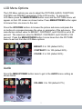
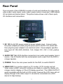
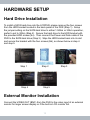
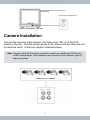
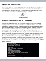
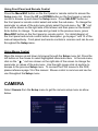
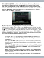
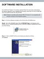
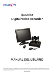
1
LCDDVR4 User’s Manual
2-IN-1 4-CHANNEL DIGITAL VIDEO RECORDER
AND 10.2" LCD MONITOR
Available models with hard drive:
LCDDVR4-80 (with 80GB SATA HD)
LCDDVR4-320 (with 320GB SATA HD)
Copyright Notice
This manual is furnished under license and may be used or copied only in accordance with the terms of such license. Except as permitted by such license , no part of this publication may be reproduced , stored in a retrieval system , or transmitted , in any form or any
means , electronic , mechanical . Recording, or otherwise, including translation to another language or format, without the
prior written permission of SecurityMan. The content of this manual is furnished for informational use only, is subject to change without
notice, and should not be construed as a commitment by SecurityMan. SecurityMan assumes no responsibility or liability for any errors
or inaccuracies that may appear in this book. All other product names, trademarks and registered trademarks in this
document are the properties of their respective holders.
FCC Information
Notes on FCC’s “Consistent Statement of Information” This product meets the requirements specified in Part 1 5 of FCC Regulation.
Operation rests with the following two conditions:
(1 ) The equipment should not cause any harmful interference .
(2 ) The equipment must receive and process any interference , Including any possible interference caused
by operation Mistakes .
Warranty
SecurityMan warrants this product will be free from defects in materials and workmanship for a period of one year; otherwise, specified on the product packaging. This limited warranty shall commence from the date of purchase. SecurityMan products warranty is
not transferable and is limited to the original purchaser. If the product is found to be defective then, as your sole remedy and as the
manufacturer’s only obligation, SecurityMan will repair or replace the product. This warranty shall not apply to products that have been
subjected to abuse, misuse, abnormal electrical or environmental conditions, normal wear and tear or any condition other than what can
be considered normal use.
Limitation of Liability
The liability of SecurityMan arising from this warranty and sale shall be limited to a refund of the purchase price. In no event shall SecurityMan be liable for costs of procurement of substitute products or services, or for any lost profits, or for any consequential, incidental,
direct or indirect damages, however caused and on any theory of liability, arising from this warranty and sale. These limitations shall
apply not withstanding any failure of essential purpose of any limited remedy.
Operating Restrictions
DO NOT use this product to violate one’s privacy. Monitoring one’s private activities without consent is illegal and this is not designed
and manufactured for these purposes.
DO NOT use this product for any illegal activities. SecurityMan shall not be responsible for any consequences of illegal conducts made
by users.
SecurityMan®
4601 E. Airport Drive, Ontario, CA 91761, USA
Tel: 888-977-3777 or 909 -230-6668
Email: [email protected]
Fax: 909-230-6889
Website: http://www.securitymaninc.com
Made in China
Copyright 2010 by SecurityMan v4.0
TABLE OF CONTENTS
INTRODUCTION
FEATURES
PACKAGE INCLUDES
HARDWARE BASIC
LCD CONTROL
1
1
2
2
2
LCD MENU OPTIONS
3
AUDIO
3
FUNCTION
4
SYSTEM
5
PRESET
6
FRONT PANEL
7
REAR PANEL
10
SIDE PANEL
12
RC (REMOTE CONTROL)
12
GETTING STARTED
HARDWARE SETUP
14
15
HARD DISK DRIVE INSTALLATION
15
EXTERNAL MONITOR INSTALLATION
15
CAMERA INSTALLATION
16
SENSOR INSTALLATION
17
ALARM INSTALLATION
18
MOUSE CONNECTION
19
POWER ON DVR & HDD FORMAT
19
MENU SETUP & CONFIGURATION
21
USING FRONT PANEL AND REMOTE CONTROL
24
USING MOUSE CONTROL
24
CAMERA
24
CHANNEL
25
DISPLAY
25
BRIGHTNESS
25
CONTRAST
25
HUE
25
SATURATION
25
RECORD
26
RECORD FRAMERATE
26
RECORD QUALITY
27
RECORD SCHEDULE
28
ALARM
30
ALARM DURATION
30
BUZZER DURATION
31
EVENT REC DURATION
31
SENSOR
31
MOTION DETECTION
32
SCREEN
34
BORDER
34
AUTO SEQUENCE
34
VIDEO ADJUSTMENT
35
AUDIO
35
SYSTEM
36
HARD DISK SETUP
37
OVERWRITE ENABLE
37
FORMAT HDD
37
ACCOUNT SETUP
39
ACCOUNT
39
PASSWORD
40
LEVEL
40
PASSWORD/PASSWORD SETUP
41
KEYPAD TONE
42
TIME SET
42
EVENT LIST
43
PTZ SETUP
43
BUTTON FUNCTION FRONT PANEL/REMOTE CONTROL
45
REMOTE CONTROL
45
MOUSE FUNCTION
45
PRESET SETUP
45
PTZ MODE
46
ICON FUNCTION WINDOW
46
ATTENTION
46
F/W UPGRADE
46
LOAD SETUP DEFAULT
47
SEARCH:PLAYBACK
47
PLAYBACK CONTROLS USING FRONT PANEL OR
REMOTE CONTROL (RC)
48
PLAYBACK CONTROLS USING MOUSE
49
BACKUP TO USB MEMORY STICK
50
LANGUAGE
52
LOGOUT
52
EXIT
53
SOFTWARE INSTALLATION
SOFTWARE UNINSTALLATION
PC PLAYBACK
54
57
58
SOFTWARE BASIC & PLAYBACK
58
CONTEXTUAL MENU
61
OPEN FILE...F2
61
OPEN DISK
61
EXPORT (*.VVF TO *.AVI CONVERSION)
62
CLOSE OR F4
63
SHOW TIME
63
ALWAYS ON TOP
64
PLAYBACK
64
CAPTURE
64
AUDIO
65
FULL SCREEN
65
MAXIMIZE
65
ASPECT RATIO
65
SPLIT MODE
65
ABOUT VIEWER OR F1
66
EXIT OR ALT+F4
66
APPENDIX
67
RECORD TIME
67
SPECIFICATIONS
68
SYSTEM CONNECT MAP DIAGRAM
69
COMPATIBLE USB FLASHDRIVE
70
Q&A
70
INTRODUCTION
Thank you for purchasing LCDDVR4 system. The LCDDVR4 system is a spacesaving LCD & DVR 2-in-1 solution for homes and small businesses. It is composed of both 10.2” color LCD monitor and a 4-channel digital video recorder in
one. It is a total digital video surveillance system with duplex functionality; the
ability to simultaneously playback while in recording. Compact designed for
limited space area and simple to install, wall-mounted or place on desktop. Easy
access control using remote control, panel buttons, or mouse control with the
touch of a button.
Features
• Space saving LCD/DVR combo design
• 10.2˝ flat panel LCD color monitor with desktop and wall-mountable base
• Easy to use 4-ch duplex DVR (simultaneous playback/record)
• 2-ch audio inputs and 1-ch audio output
• Recording speed up to 60fps total (up to 30fps each camera)
• One internal SATA hard drive (i.e. 80GB/320GB records about 50hrs/200hrs @
default settings 30fps & normal quality)
• Selectable recording modes: Continuous, Motion detection, Sensor activated,
Time Schedule, and both Sensor & Motion detection.
• Easy access using a remote controller or a mouse control
• Easy back up to a portable USB flash drive and playback from a PC
• Power recovery auto record function
• RS485 port for protocol camera; Pelco-P/D
• I/O: 4 inputs and 1 output terminals
• Video loss alarm function
• Ideal security system for homes and small businesses
1
PACKAGE INCLUDES
• LCDDVR4 w/ mounting bracket stand
• Power adapter with cable
• Remote Controller (batteries included)
• PS/2 Mouse
• Software CD (for PC)
• User Manual
• Ground Cable and screws
Hardware Basic
LCD Control
Top Panel
1) MENU/POWER: Press and hold for 2 seconds to turn ON/OFF the LCD
monitor. Press MENU/Power button to get to the LCD menu and press it
again to browse through the display menu options.
2) UP: In the LCD menu, press the UP button to browse up the menu options.
3) DOWN: In the LCD menu, press the DOWN button to browse down the
menu options.
4) + : In the LCD menu, press the + button to change or increase the
parameter/value.
5) - : In the LCD menu, press the – button to change or decrease the
parameter/value.
2
LCD Menu Options
The LCD Menu options are use to adjust the PICTURE, AUDIO, FUNCTION,
SYSTEM, and PRESET parameters of the LCD monitor. To access the
LCD Menu press the MENU/POWER button once and the PICTURE menu will
appear on the LCD screen as shown below. Press MENU/POWER button again
to browse from one menu to the next.
Press the UP/DOWN buttons to browse the picture sub-menu and press the
+/- buttons to increase/decrease the value or parameter of the sub-menu. The
manufacture default value for BRIGHT, CONTRAST, and COLOR is set at 50
percent. The maximum value for BRIGHT, CONTRAST, and COLOR is 100
percent. Press the MENU/POWER button 5 more times from the PICTURE
menu to exit out from the LCD Menu options.
BRIGHT: 0 to 100 (default 50%)
CONTRAST: 0 to 100 (default 50%)
COLOR: 0 to 100 (default 50%)
Audio
Press the MENU/POWER button twice to get to the AUDIO menu setting as
shown below.
VOLUME: 0 to 100 (default 27%)
3
Note: This is volume control for the LCD monitor and it is the master volume control that dominates over the recorder’s volume control. If volume level is set
too high, the microphone gain from the camera may sound distorted.
The AUDIO menu is use to adjust the LCD volume level which dominates over
the recorder’s volume control level. Press the +/- buttons to increase/decrease
the volume level of the LCD monitor. The manufacture default volume level is set
at 27 percent. Press the MENU/POWER button 4 more times from the AUDIO
menu to exit out from the LCD Menu options.
Function
Press the MENU/POWER button 3 times to get to the FUNCTION menu setting
as shown below.
Dis. Ratio: 16:9, 4:3 (default 16:9)
Note: In a 16:9 display ratio, it is normal for the images to zoom or stretch to a full
screen display. However, the 4:3 display ratio will display normal images on
the screen but will not display in full screen.
The FUNCTION menu is use to adjust the display ratio of the LCD screen. The
display ratio manufacture default setting is 16:9. Alternatively the ratio can be
4
change to display in 4:3 ratio. To toggle between the display ratio press the + or
– buttons. Press the MENU/POWER button 3 more times from the FUNCTION
menu to exit out from the LCD Menu options.
System
Press the MENU/POWER button 4 times to get to the SYSTEM menu setting as
shown below.
S-ROLOC: AUTO, NTSC, SECAM, &
PAL (default AUTO)
Note: Please use default AUTO setting unless the video format intended does not
display correctly. Displays in black and white and/or rolling images, and
then select the correct video standard used for your country. The NTSC
and PAL jumper setting located inside (behind the HDD cover) the DVR has
priority over SYSTEM/S-ROLOC settings; the default jumper setting inside
the DVR is set to NTSC for North America and other NTSC countries.
The SYSTEM menu is use to configure the type of video format the LCD display.
Press the + or - buttons to toggle between the different video format. The manufacture default S-ROLOC setting is set to AUTO. Alternatively it can be change
between AUTO, NTSC, SECAM and PAL video format, check your country code
for video standard. Press the MENU/POWER button 3 more times from the
FUNCTION menu to exit out from the LCD Menu options.
5
Preset
Press the MENU/POWER button 5 times to get to the PRESET menu setting as
shown below.
SLEEP: 0~24 0Mins. (default 0)
TIME: setup current time (default --)
OFF-TIME: setup time for LCD to turn
off (default --)
ON-TIME: setup time for LCD to turn
on (default --)
Note: OFF-TIME has to exceed the TIME and ON-TIME. SLEEP (countdown timer)
and TIME (interval) feature works and operates independently.
The PRESET menu is use to setup SLEEP and TIME (OFF-TIME, ON-TIME). In
PRESET menu press the UP/DOWN buttons to browse up and down the menu.
Press the + or - buttons to change the value or perimeter. The – button is use to
decrease the SLEEP value and increase the hour for TIME setting. The + button
is use to increase the SLEEP value and increase the minute for TIME setting.
SLEEP and TIME are two independent features; please use one or the other
feature. The SLEEP value can be set between 0~240 minutes with an increment
of 10 minutes, the default value is 0. SLEEP is a countdown timer; the time that
take for the LCD monitor to automatically turn off (not the DVR). The TIME mode
can be setup by first setting the current time of day for TIME value. Next, using the TIME setting as guidance, setup the OFF-TIME and ON-TIME setting to
automatically turn OFF and ON the LCD monitor respectively. Press the MENU/
POWER button one more time from the PRESET menu to exit out from the LCD
Menu options
6
Front Panel
The front panel consists of a LCD display screen (above the function buttons), a
speaker (to the left of the function buttons), and DVR function buttons use to control and configure the DVR. The front panel buttons is use to operate the DVR’s
basic functions such as; record, playback, fast-forward, reverse playback, and
etc. Below is a list of basic buttons and its functionalities:
Front Panel
1) CH1↑, CH2↓, CH3←, CH4→, & QUAD buttons is use to display the camera
channel in full screen or in quad split screen for all 4 channels. To display
full screen for camera 1 simply press the CH1 button once. In the menu
mode, CH1↑, CH2↓ and CH3←, CH4→ buttons are use browse and change
parameter settings respectively. Press CH1 again or press the QUAD button
to get back to quad split screen view.
2) REC button is use to initiate recording and stop recording. To start recording,
press REC button to start manual recording. The ● REC will appear on
screen in red to show the DVR is in record mode. Press the REC button
again will end the recording process, password may require depending on
system configuration.
3) STOP button is use in playback mode. Press the STOP button in playback
mode to stop the video from playing back.
4) PLAY button is use to search and playback the recorded video file. Press
the PLAY button to start time and date Time Search. Press the PLAY button
7
again to start playing back the oldest data that exist in the hard drive. From
the Time Search menu option, press the SEL/EDIT button to enter query time/
date search. Press the UP/DOWN button to browse and press the SEL/EDIT
button to change the value. Press the MENU/ESC button to accept and
confirm time/date search and then press the PLAY button to start searching.
In play or playback mode, press the MENU/ESC button at any time to activate
file backup, please reference file backup section of the manual.
5) FWD button is use to fast forward in playback mode and also use to activate
auto sequence if and only if the Auto Sequence is turned on in the system
menu.
To fast forward during playback, press the FWD button. There are three
levels of fast forwarding speed as follow:
a) The
FF : Playback at 2X times the normal speed.
b) The
FF : Playback at 3X times the normal speed.
c) The FF: Playback at 4X times the normal speed.
To toggle between the fast forward speeds, press the FWD button once,
twice, or 3 times during playback to fast forward the video footage. Press
the PLAY button at anytime to exit out from FF mode and get back to normal
playback speed.
6) REW button is use to rewind in playback mode. To rewind during playback,
press the REW button. There are three levels of rewinding speed as follow:
a) The
REW: Rewind playback at 2X times the normal speed.
b) The
REW : Rewind playback at 3X times the normal speed.
c) The
REW : Rewind playback at 4X times the normal speed.
To toggle between the rewind speeds, press the REW button once, twice, or
3 times during playback to rewind the video footage. Press the PLAY button
at anytime to exit out from REW mode and get back to the normal playback
speed.
Note: The fast forward and rewind playback speed varies depending on the frame
rate, the record quality settings, and the number of channels recorded.
7) PAUSE button is use to pause the playback footage in playback mode. To
pause the playback video, press the PAUSE button once. In pause mode,
press the ▲ UP/▼DOWN buttons to playback video footages step by step or
8
frame-by-frame. To continue normal playback, press the PLAY button.
8) MENU/ESC button is use to access the main menu of the DVR. The main
menu is use to configure and setup parameter of the DVR. Press the ▲ UP/
▼ DOWN button to browse through the main menu. In playback mode, the
MENU/ESC button is use to access file backup panel. Press the MENU/ESC
button at anytime to exit out from the menu.
9) ▲ UP / ▼ DOWN button is use to browse/toggle or change a menu field. In
playback mode, the ▲ UP/▼ DOWN button is use to playback footages frameby-frame accordingly.
10) SEL/EDIT button is use to select and/or change the value in main menu or
sub menu setting.
11) PWR, HDD, & IR are light indicators and IR for the remote control. Color
light indicator and their meanings:
a) PWR: Solid green light DVR has power and it is up and running.
No light indicates the DVR is not powered on or power failure.
b) HDD: Constant flashing red light indicates the system is in Record
mode and/or in playback mode. No light indicates that the DVR is not
in record mode or in playback mode.
c) IR: The IR is the remote control receiver window. Remote control
needs to be pointing towards the IR receiver window for efficiency.
12) PTZ button is use to enter PTZ control screen. PTZ mode is used when
supported protocols camera are installed; currently supporting Pelco-P and
Pelco-D.
9
Rear Panel
The rear panel of the LCDDVR4 consists of ports and interfaces for video inputs,
video output, audio inputs, audio output, power socket, mouse port, HDD bracket,
I/O terminals and bracket stand. The picture below shows a list of basic ports,
I/O interfaces and connections:
1) DC 12V: An AC/DC power socket for power adapter input. Connect using
the power adapter provided; plug the power jack to the DC 12V socket and
then plug the power adapter to an electrical outlet. Power adapter specifica
tion: Input: AC 100~240V, 50/60Hz, 1.5A / Output: DC +12V == 5.0A, positive
inside.
2) AUDIO OUT (1x): RCA interface connection to an audio input speaker (mono)
source. Use to transfer both live and playback audio output from the DVR to
a larger speaker.
3) POWER: This is the main power switch for the DVR, to switch ON/OFF.
4) VIDEO OUT: For monitor output to a TV monitor, CCTV monitor and etc.
Video output is BNC connector interface use ideally to output the display into
a larger monitor display or if the LCD display gone bad. The VIDEO OUTPUT
works in parallel with the built-in LCD monitor, however the LCD menu will not
display through to the video output. It can also be connected into a VHS
device for tape backup.
10
5) AUDIO 1/2 IN: Connect up to 4 audio microphone cameras into the audio
input ports. Only one audio port can be active for monitoring and recording.
If one audio input is connected into AUDIO 1 IN and the AUDIO menu is setup
for channel 1, audio will output in channel 1 full screen view and in quad view.
However, if audio input is connected to AUDIO 1 IN and AUDIO menu is setup
for channel 1, viewing channel 2/3/4 in full screen will mute the audio output.
6) PS2 MOUSE: Use this port for PS/2 mouse connection. If you have USB port
mouse, use USB - PS/2 adapter to connect with this port.
7) HDD Bracket: The HDD bracket is use to mount the system hard disc drive.
8) VIDEO INPUT: connect up to 4 cameras into the corresponding video input
ports. Video input is BNC connector interface, converters required for RCA
interface cameras.
9) RS485/ SENSOR/ ALARM:
RS485
The first two terminals from left to right is the RS485 power line ports use for
protocols camera. RS485 two terminals are – and +. Only two protocols
are supported, Pelco-P or Pelco-D protocols camera with RS485 terminal
to integrate.
ALARM
This is an alarm input terminal use to connect dry contact of an output device
such as a siren, spot light and etc. The output device requires having its own
power to integrate. The alarm terminal does not provide any power to the
output device.
SENSOR
There are 4 sensor input terminals total, in which up to 4 sensors can be con
nected to the DVR. Each sensor input consists of 2 terminals, because it is a
relay terminal. The input terminals can be configured to trigger video recording. If the input is motion detection, motion can also be configured to trigger
video recording.
Note: Mount the ground cable (green) to the GND screw located below the Power
switch and secure the other end of the ground cable to a ground source.
Grounding the DVR will help to prevent surge and protection from other
unknown static.
11
Side Panel
The right side panel consists of a USB port use for backup purposes and update
firmware. The USB port is dedicated for backup purposes only; alternatively,
USB mice will be compatible and will not function through this USB port.
RC (Remote Control)
12
1. CH1 ↑
5. QUAD
6. ◄◄ / Z7. ► / F+
8. ►► / Z+
9. ●
10. ▌▌ / F11. ■
Select, CH1 full screen, Move up (PTZ), Move cursor up, FF
frame-by-frame
Select, CH2 full screen, Move down (PTZ), Move cursor
down, REW frame-by-frame
Select, CH3 full screen, Move left (PTZ), Move cursor left or
Reduce value
Select, CH4 full screen, Move right (PTZ) or Move cursor right
or Increase value
Quad View
Rewind / Zoom-(PTZ)
Time search playback / Focus+ (PTZ)
Forward or Channel auto sequence switch / Zoom+(PTZ)
Manual recording, Stop manual recording or Level scan
Pause / Focus- (PTZ)
Stop playing or Stop dome running (PTZ)
12. PTZ
13. Menu/ESC
14. Select/Enter
15. UP
16. DOWN
PTZ Switch
Enter or exit setup menu
Select, modify item or Increase value
Scroll up prompt or play forward frame-by-frame
Scroll down prompt or play backward frame-by-frame
2. CH2↓
3. CH3 ←
4. CH4 →
13
GETTING STARTED
Install a SATA hard disk drive into HDD bracket located at the back of LCDDVR4
panel by removing the four screws (Philips) from the HDD bracket. Connect the
data and power cable to the SATA hard disk drive, seat the HDD bracket back
into the slot and secure it with the four screws. Hook up to 4 cameras with BNC
interface into the video inputs of the DVR. Connect the PS/2 mouse, external
sensors (if any), alarm, GND cable, audio in/out, and etc. into the DVR back
terminals. Plug the power adapter into the back of the DVR and the other end
plugs into an electrical outlet. Power on the DVR by switching the main power
ON, located at the lower left corner of the back panel and then both the DVR and
LCD monitor will automatically boot up the user interface screen. Press the REC
button to start the recording process and press the PLAY button to start playback
recorded file. More detail overviews of this summary below.
Note: If the power adapter is accidently unplugged or there is a power failure during
recording and when the power comes back; the DVR will detect the failure,
enter “Power Recovery” mode, and then reinitiate the recording process.
14
HARDWARE SETUP
Hard Drive Installation
To install a SATA hard drive into the LCDDVR, please remove the four screws
from the HDD bracket located in the back panel of the DVR (Step 1). Setup
the jumper setting on the SATA hard drive to either 1.5Gb/s or 3Gb/s operation,
prefer to set to 3Gb/s (Step 2). Secure the hard drive to the HDD bracket with
the provided HDD screws (4x). Then connect the Power and Data cable of the
DVR to the SATA hard drive (Step 3). Slips the HDD bracket back into its slot
and secure the bracket with the four screws (blk), as shown below in step 4
and step 5.
Step 1
Step 4
Step 2
Step 3
Step 5
External Monitor Installation
Connect the VIDEO OUT (BNC) from the DVR to the video input of an external
monitor for larger screen display or if the built-in LCD monitor fail.
15
The DVR VIDEO OUT to External monitor
VIDEO INPUT.
DVR OUT to external monitor
Monitor “VIDEO INPUT “ from DVR
Camera Installation
Connect the camera’s Video Output to the Video Input “IN1~4” of the DVR
located in the rear. Plug the camera power to the camera and the other end into
an electrical outlet. Connection diagram illustrated below.
Note: Camera using RCA interface connection requires an additional RCA female
to BNC male adapter. Other adapters may require for other different types of
camera interface.
“VIDEO OUT” from CAMERA
VIDEO IN 1
VIDEO IN 2
VIDEO IN 3
VIDEO IN 4
16
Sensor Installation
There are a total of 4 sensor input terminals located in the rear of the DVR. The
sensor input is use to setup hard wire external sensor such as motion sensor,
window/door sensor, and etc. Since the terminal does not provide power to
the input devices, the sensor is required to have its own power. There are two
simple steps to install hard wired sensor input as follow:
• Choose one of the four terminals to connect the sensor into. Connect
the sensor signal lines to the SENSOR input terminal as shown in the
picture diagram below.
• If the sensor requires power, use the power from the sensor device, plug
the power jack into the sensor and then plug the other end of the power
adapter to an electrical outlet.
Note: Most input may not require power. Each sensor input terminal corresponds to
the actual camera channel. For example; Sensor #1 interacts with channel #1
camera, sensor #2 corresponds with channel #2 camera and so on
Generally, there are three different types of sensor configurations: Normally
Close, Normally Open, and Normally Close & Open (N/A). For LCDDVR4 only
two of the three configurations used; Normally Close, Normally Open, or None
(default setting). Most commonly used is the Normally Open relay. Below are
general diagrams of the different sensors relay and how they are installed in
conjunction to the LCDDVR4 terminals:
17
Normally Close
Normally Open (Common)
Normally Close & Open (N/A)
After the sensor hardware has been setup according to the above illustrations,
next is to activate the sensor via the MENU setup on the LCDDVR4. To active
the sensor in the MENU setup please advance to page 28 and 29 of this manual.
Alarm Installation
The unit provides 1 internal switch for sounding alarm when the sensor is activated. The switch is open at normal state a wiring diagram is illustrated below.
When the alarm is activated, the switch becomes close so that the alarm gets the
power to trigger at closed circuit. There are two simple steps to install hard wired
alarm output as follow:
1.Connect the alarm power lines to the ALARM switch terminal as shown in
the diagram below.
2.Then connect the power adapter of the alarm device to an electrical outlet.
ALARM OUTPUT terminal
18
Mouse Connection
Connect the PS/2 mouse to the PS2 MOUSE port of the DVR located in the back
of the DVR. Mouse control is one of the most convenient way of controlling the
DVR, setup and configure the DVR. If mouse is lost or stolen, any PS2 mouse
should be fully compatible with PS2 MOUSE port and DVR.
Power On DVR & HDD Format
Connect the power jack (Input: AC 100~240V, Output: 12VDC 5.0A, positive
inside) into the power socket located in the rear of DVR and then connect the
other end to an electrical outlet. Power on the LCDDVR4 with the power switch
and the DVR will start to boot into dos mode scanning for new hard disk drive.
If new hard drive is detected, it will prompt to configure or format before the
system gets to the user interface window. To proceed and format the new
hard disk drive, press the PLAY button using the remote control or front panel
button. Once disk format is successful the “Format….OK” will display on screen
to indicate the hard disk has been successfully formatted as illustrated below.
To cancel the formatting process, press the STOP button using the remote
control or front panel button. Formatting only require one time for newly installed
hard drive; any reboot thereafter will skip the format process in the dos boot up
and boots to the user interface screen. To pause in dos boot up, press the STOP
button at anytime.
19
After the initial boot, the DVR advance to the user interface screen. The user
interface consists of 4 channel (QUAD) view along with the channel number, disk
use percentage, date and time display as shown below:
20
MENU SETUP & CONFIGURATION
To enter the MAIN SETUP MENU press the Menu/ESC button on the remote
control, front button panel or right-click button on the mouse and a login window
will appear as shown above. There are three Account/Password level;
the Admin account (highest, default), the Operator account, and the Guest
account (lowest). By default the system has the password set to ON which
require operator to input in a login name or account and a login password.
When the password is in the ON mode, after login if the system is idle for a
period of 5 seconds, a login name and a login password is require to be input in
again due to inactivity. The period of inactivity is automatically determined by the
DVR system.
The Admin (administrator) has full controls of the DVR system; setup login
name, password and accounts level for each account users. Only one system
Admin account per a system, a second Admin account cannot be created. Besides the Admin account, up to 3 additional accounts can be created alternating
between Operator and Guest. Please reference Account Setup on page 39 for
more detail.
The Operator account can perform tasks similar to that of the Administrator
account except for the following restrictions; operator cannot alter or add users
account setup, operator cannot format the HDD, restricted from run firmware
update, and cannot load setup default setting. However, in Operator account
level has the privilege to change its own Operator password.
The Guest account has the least priority of all account levels, more restrictions, which limits to parameter value change and setup functionality. Guest
account level of operation is suitable for live video viewing and playback
purposes. Here are the list of privileges that Guest account level can do; [live
21
view channel 1~4], [playback recorded image file], [setup>camera> channel
1~4], [setup>alarm>motion detection>channel view 1~4], [setup>screen>
boarder/auto sequence], [setup>audio>channel 1~4], [setup>system>password
setup/password on-off/key tone/event list], [setup>search for playback recorded
image files or events], and [setup>language selection]. In Guest account login,
the identifier “ ” icon will appear on the top right hand corner of the screen if the
restricted setting(s) is selected.
From the “Login” screen, left mouse click on or press SEL/EDIT button or use the
remote to select Account and an Account keyboard window will appear as illustrated above. Inputs in the account login name by select the characters/numbers
on the keyboard window using either left click from the mouse control or press
SEL/EDIT button (panel/RC) or use the up/down/left/right/enter buttons on the
remote control or front panel to browse/select. Select Enter to save and accept
the account login name.
Select the Password option from the “Login” screen and the password window
will appear as shown above. Input the passwords to the account login name
using either left click on the mouse control or press SEL/EDIT button (panel/RC)
or use the up/down/left/right/enter buttons on the remote control or front panel to
browse/select. Select Enter to save and accept the password. Finally, click on
or select the Login in the “Login” window to login into the system Setup Menu.
The manufacturer default administrator account and password is “admin” and
“111111” respectively. Please use the system default account/password to login
to the LCDDVR4 for the first time.
After login the system, right click on the mouse to open up the Setup Icon menu
window as shown below. Using the mouse control will get to the Setup Icon
menu window, however if the MENU/ESC button (panel/RC) is use the Setup
menu will appear as shown below
22
Setup Icon menu window (mouse only):
Channel 1 full screen button
Channel 2 full screen button
Channel 3 full screen button
Channel 4 full screen button
Quad Channel view button
Manual Start/Stop REC button
Playback Time Search button
PTZ switch
Channel auto sequence button
*The auto sequence icon “
” will not show in the
Setup Icon menu window if the “Auto Sequence”
feature is turn OFF.
Setup menu button
Logout of Setup Icon menu
*The
logout button will not show in the Setup
Icon menu window if the “Password” feature is set
to ON or if the auto sequence is set to ON.
If
is present in the Setup Icon menu, press the
icon to stop auto
sequence, press again to start auto sequence. To exit out of the Setup Icon
menu without logout; simply right mouse click anywhere on the screen. Use
the left mouse click on the
icon and the Setup menu will appear as
shown above. The Setup menu is use to make change to the DVR setting and
configuration parameter.
23
Using Front Panel and Remote Control
Press the Menu/ESC button on the front panel or remote control to access the
Setup menu list. Press the UP and DOWN button on the front panel or remote
control to browse up and down the Setup menu. Press SEL/EDIT button on
the front panel or remote control select and enter the sub-menu. To change the
parameter or values of the sub-menu simply select the sub-menu, the “
” red
icon will be shown on the right side of the screen and then press on the Select/
Enter button to change. To escape and go back to the previous menu, press
Menu/ESC button on the front panel or remote control. For detail diagram of
the front panel and remote control button description, go to page 7 and 12 of the
manual respectively. Front panel and remote controls is common and can be use
throughout the Setup menu.
Using Mouse Control
Move the mouse up and down to browse through the Setup menu list. Press the
left button on the mouse to select highlighted menu/sub-menu. In the sub-menu,
click on the “
“ red icon shown on the right side of the screen to change the
parameter or values of the sub-menu. Use the right mouse click at anytime to
escape to the previous Setup menu. To connect the PS/2 mouse to the DVR,
please reference page 19 of the manual. Mouse control is common and can be
use throughout the Setup menu.
CAMERA
Select Camera from the Setup menu to get the camera setup menu as show
below.
24
Camera menu consist of Channel, Display, Brightness, Contrast, Hue,
and Saturation.
CHANNEL
Channel is use to toggle between camera channels, ie channel 1, channel 2,
and etc for the purpose of adjusting and fine tuning the camera image. Channel
name 1, 2, 3, 4 cannot be change. Or, press the left and right arrow of the front
panel or remote control to change value respectively.
DISPLAY
Display can be use to turn ON (Default setting) or turn OFF the channel name
display. The channel names are channel identity used to identify each channel
by name or number; in this case the channel names are fixed by default. The
display default setting is set to ON. Or, press the left and right arrow of the front
panel or remote control to change value respectively.
BRIGHTNESS
Brightness is use to tune up and down the bright level of an image in the
selected channel. Click on the left red arrow to reduce the brightness level and
click on the right red arrow to increase the brightness level of the image. Or,
press the left and right arrow of the front panel or remote control to change value
respectively.
CONTRAST
Contrast is use to tune the depth and sharpness of the image. Click on the left
red arrow to decrease the contrast and click on the right red arrow to increase
the contrast of the image. Or, press the left and right arrow of the front panel or
remote control to change value respectively.
HUE
Hue is use to adjust the variety of color spectrum in the image. Click on the left
red arrow to decrease the color glow and click on the right red arrow to increase
the color glow in the image. Or, press the left and right arrow of the front panel or
remote control to change value respectively.
SATURATION
Saturation is use to adjust the purity of the colors in the image. Click on the left
red arrow to decrease the purity of a color. Or, press the left and right arrow of
the front panel or remote control to change value respectively.
25
Note: The manufacturer default setting for Brightness, Contrast, Hue and Saturation
is centered at 50%.
RECORD
Select Record from the Setup menu to get to the record setup menu as show
below. The Record setup menu consists of Record FrameRate, Record Quality and Record Schedule. Press the Menu/ESC on the front panel, remote
control or single right-click on the mouse at any time to exit out of Record menu
to the main Setup menu.
RECORD FRAMERATE
Select the Record FrameRate from the Record Setup menu to access the
record frame rate setting as illustrated in the picture below. The default Record
FrameRate setting is 30fps (frame per second) total; by default channel 1 is set
to 8fps, channel 2 is set to 8fps, 7fps for channel 3, and 7fps for channel 4.
The maximum fps (frame per second) total for all 4 channels can be set to 60fps;
single channel fps can be set up to 30fps. To browse the Record FrameRate
setup menu; press the UP/DOWN or CH1↑/CH2↓ buttons on the front panel,
remote control or use the mouse to hover over the channels. The Record
FrameRate can be setup to the following value:
26
OFF, 3fps through 30fps. To change the value, press the CH3←/CH4→ buttons
on the front panel, remote control or left mouse click on the ◄ ► red arrows to
decrease and increase [Select/Enter button on the front panel or remote control
(RC) can also be use to increase frame rate value] the recording frame rate respectively. The higher the record frame rate the more natural the movements will
be in playback mode. Each channel can be setup with different frame rateor independent of one another, a maximum of 30fps can be setup per channel. Total
Used Frame is automatically calculated by the DVR system, frame rate can also
be set to OFF meaning that the channel (camera) will NOT be recording. Press
Menu/ESC button on the front panel, RC or right –click on the mouse at any time
to exit out from Record FrameRate setup menu
RECORD QUALITY
In the Record setup menu browse down to Record Quality and the ◄ ►
red arrows will appear. Press the Select/Enter button on the front panel, RC
(Remote Control) or left mouse click on the red arrows to decrease and increase
the record quality respectively. There are 3 Record Quality levels; level 1
has the lowest record quality, level 2 is normal record quality (System Default setting), level 3 has the highest record quality. The higher the Record
Quality the better the video image quality will be in playback mode. The higher
the Record Quality the more the hard disk space is needed because higher
record quality contains larger file size per frame rate.
Note: The Record FrameRate setting, Record Quality setting and hard disk size will
affect total record time of DVR system. In Chinese captions the best Record
Quality is 4, the worst Record Quality is 2.
27
RECORD SCHEDULE
In the Record setup menu browse down to select Record Schedule, press the
Menu/ESC button on the front panel, RC (Remote Control) or left mouse click to
access the Record Schedule window as illustrated below. Press the CH1↑/(UP),
CH2↓/(DOWN), CH3←, CH4→ buttons on the front panel, RC or mouse to move
around to the time and days of the week and then press the Select/Enter button
on the front panel, RC or left mouse click to change value box. Record Schedule consist of time interval from 0 to 24 hours, Sunday to Saturday, Manual
record bar (gray), Time record bar (schedule, red), Motion record bar (green),
Sensor record bar (yellow), and Motion & Sensor record bar (yellow-green) settings. The time interval from 0 to 24 hours and Sunday to Saturday setting is a
matrix designed for a full week of scheduling.
Manual record setting is the systems default setting in which the bars are color
coded gray in the schedule matrix. Manual record mean to initiate recording; the
record button will have to be press on each time to start the recording process
and press on again to manually stop the recording process.
Time record; press the Select/Enter button or mouse click once on the gray bar
to toggle between gray bars to red bar which is Time or schedule record. Time
record mean at the exact time of day scheduled, the DVR will automatically initiate the recording and stops the recording when the time scheduled end.
Motion record; move the cursor to highlight the desire time/date of the week and
then press the Select/Enter button on the front panel, RC (Remote Control) or
28
left mouse click twice to change from gray bar to red bar and into the
bar for motion record schedule.
green
Sensor record; move the cursor to highlight the desire time/date of the week and
then press the Select/Enter button on the front panel, RC (Remote Control) or
left mouse click three times to change from gray bar to yellow bar and into the
yellow bar for sensor record schedule.
Motion & Sensor (both) record; move the cursor to highlight the desire time/
date of the week and then press the Select/Enter button on the front panel, RC
(Remote Control) or left mouse click four times to change from gray bar to yellowgreen bar and into the
yellow-green bar for motion & sensor (both) record
schedule.
IMPORTANT NOTE: Motion record schedule requires additional setup in
Motion Detection Sensitivity and Motion Area to complete Motion detection
configuration setup, see page 32. Sensor record schedule requires sensor
setup in Alarm configuration to complete sensor record setup, see alarm
configuration below and alarm connection on page 17. Right click anywhere
on the Record Schedule menu window or press Menu/ESC button on the
front panel or RC at anytime to exit.
Another and faster way to mask (more than one bars at a time) the bars is to
press the QUAD button on the front panel or RC while in the Record Schedule
window to change the cursor from pink to blue (teal) color. Next use the CH1↑/
(UP), CH2↓/(DOWN), CH3←, CH4 button on the front panel or RC to widen the
area to mask. Once the area is confirmed and ready to be masked, press the
Select/Enter button once on the front panel or RC to mask the selected area
to Time Schedule (red bar), press Select/Enter button again to mask Motion
Schedule (green bar), press Select/Enter button again to get to Senstor Schedule (yellow bar), and press Select/Enter button again to get to Motion & Sensor
Schedule (yellow-green bar). Press Select/Enter button one last time to get
back to the default Manual Schedule (gray bar, default).
In a similar way, the mouse can also be used to quickly mask the Record Schedule bars. To mask more than one schedule bars; click and hold down the left
mouse button at a desire time/date of the week and then drag the mouse cursor
to create an area to be mask. Once confirmed, release the left mouse button (Do
29
not move the mouse or mouse tracking after the left button is released) and
then left click once on the mouse to mask the bars to Time Schedule (red bar),
left click again to mask Motion Schedule (green bar), and so on.
ALARM
To access Alarm setup menu, simply browse and select Alarm from the Setup
menu and then the Alarm setup menu will appear as shown below. Alarm menu
is use to setup and configure Alarm Duration, Buzzer Duration, Event REC
Duration, Sensor (I/O) and Motion Detection (built-in MD).
ALARM DURATION
The Alarm duration refers to the alarm output (in the I/O terminal) use to setup
the alarm duration period after the alarm has been activated. It can be set to
OFF (system default), 05 seconds, 10 seconds, 15 seconds, 20 seconds, 25
seconds, 30 seconds or CON’T (continuous). To set the alarm output to last 20
seconds, please set 20 seconds. After 20 seconds the alarm output will stop.
Press Menu/ESC or right click mouse anytime to exit out of Alarm setup menu.
Note: The alarm device must be installed in the I/O terminals in order for Alarm Duration setting to be affective.
30
BUZZER DURATION
Buzzer Duration refers to the built-in buzzer sound when the alarm triggered.
It can be set to OFF (system default), 5 seconds, 10 seconds, 15 seconds, 20
seconds, 25 seconds, 30 seconds, or CON’T (Continuous). As its name imply,
Buzzer Duration is use to configure the length of time the buzzer will sound
when an event occur. Buzzer Duration is works independently from Event REC
Duration time setting. To setup Buzzer Duration browse to buzzer duration
using the front panel, remote control or mouse to hover over buzzer duration.
Change the value by pressing on the CH3← (decrease value), CH4→/[Select/
Enter](increase value) buttons on the front panel, RC or mouse click on the
◄ ► red arrows. Press Menu/ESC or right click mouse anytime to exit out of
Alarm setup menu.
EVENT REC DURATION
Event REC Duration implies to the time of recording periods after an event
occur, motion/sensor record time holding; when an event occur the DVR start to
record and end the recording when the time expire. Event REC Duration can be
set from 05 seconds, 10 seconds (system default), 15 seconds, 20 seconds, 25
seconds or 30 seconds. To change the value press the CH3← (decrease value),
CH4→/[Select/Enter](increase value) buttons on the front panel, RC or mouse
click on the ◄ ► red arrows. Press Menu/ESC or right click mouse anytime to
exit out of Alarm setup menu.
SENSOR
31
From the Alarm setup menu select Sensor to get to the sensor menu as shown
above. Sensor setup defined the native state of the wired sensor that is installed
in the I/O terminals. There are three different types of sensor setting: N.O (Normally Open), N.C (Normally Close), & NONE (system default). The wired sensor
statue may vary depending on manufacturer make; most common setting is N.O
(Normally Open) state. If unsure please refers to the user’s manual of the input
device. Select NONE if the sensor input is not being use which will deactivate
sensor recording. Press Menu/ESC or right click mouse anytime to exit out of
Alarm setup menu
Note: Sensor recording depends on Record Schedule and the present installation of
a hard wired sensor in the I/O terminal on the back of the DVR.
MOTION DETECTION
From the Alarm setup menu browse to Motion Detection using front panel,
remote control or hover over with the mouse and then press on the Select/
Enter button on the front panel, remote or left mouse click to access the Motion
Detection setup menu window as illustrated above. Motion Detection window
consist of Channel, Sensitivity and Motion Area settings. Select Channel 1
(system default), 2, 3, or 4 to start Motion Detection setup for the correspondent
channel then move cursor down to Sensitivity.
32
Sensitivity is use to adjust the sensitivity level of video motion detection (built-in
software driven) on the DVR system. The sensitivity value level can be set to
1, 2, 3, 4, and OFF (system default). The most motion sensitivity level is 1; the
higher the number, the less sensitive the video motion detection which requires
more movements in the image to trigger motion sensor. In the default OFF
position mean the Motion detection will not be detecting any motion and turn off
Press Menu/ESC or right click mouse anytime to exit out of Motion Detection
setup menu and back to Alarm setup menu.
Select Motion Area from the Motion Detection setup menu to access the
motion area setup window. Motion Area is use to mask the range of motion
detection area within the camera image. The range of motion detection block
area is limited to one block of any size, multiple motion detection block areas is
not permitted by the system.
To select or highlight motion area of detection using the front panel or RC
(remote control); move the cursor to a desire point in the image, press the
Select/Enter button once, next use the CH2↓/(DOWN) and then CH4→ button
on the front panel or RC to highlight the area of detection (blue film highlight
color), press the Select/Enter button again to confirm the selection and to
release the cursor from the highlighted block area. Press Menu/ESC button at
anytime to exit from Motion Area setup window.
To select or highlight motion detection area using mouse control; click-hold
down the left mouse click at a desire location in the camera image and then
drag the mouse cursor in a down-right directional movement to mask the area
of detection (blue film highlight color). Use right mouse click anywhere in the
Motion Area window to confirm the masking area and exit out from Motion Area.
IMPORTANT NOTE: To start Motion Record; Motion Schedule (page 28),
Sensitivity level and Motion Area must be setup as instructed above.
During Motion Area masking, the CH1↑/(UP) and CH3← button and an
upward/leftward mouse directional movement cannot be use to mask
the motion detection area.
33
SCREEN
In the main Setup menu browse down to Screen and press Select/Enter using
the front panel, RC or left mouse click to access the Screen setup menu as
illustrated below. The Screen setup menu can be use to configure Border, Auto
Sequence, and Video Adjustment.
BORDER
On the Screen setup menu, select Border. The Border configuration when turn
ON (system default) will divide the quadrant with a gray cross between the four
channels. This helps to distinguish the border line for each channel. Border
can also be set to OFF; this will disable the gray cross border between the four
channels or borderless display.
AUTO SEQUENCE
In the Screen setup menu, select Auto Sequence. The Auto Sequence is
use to setup Sequential time intervals which value can be set to OFF (Default
setting), and from 1 second up to 10 seconds. To enable auto sequence set the
dwell time between cameras to a desire time intervals and then Exit & Save
icon will display in lower left hand corner of the user interChanges. The
face screen to indicate Auto Sequence is active and the channel will display in
single full screen. For example, if the sequential time is set to 3 seconds, the
camera will display for 3 seconds and then loop to the next camera is sequential
order. However; if the camera is not connected or not installed, the Auto Sequence will automatically skip over those inactive channel(s).
34
To deactivate Auto Sequence mode; press the Menu/ESC button on the front
panel or RC, select Screen from the menu and disable Auto Sequence by
setting it to OFF. For temporary disable without turning the Auto Sequence
off, press the ►► button once to intermit auto sequence. To deactivate Auto
Sequence using mouse function; right mouse click anywhere on the image to get
to the Icon Setup Menu and then click on the
icon.
VIDEO ADJUSTMENT
Video adjustment is use to adjust, synchronize and centralize the video screen.
To synchronize the video screen, select the Video Adjustment, and then press
the CH1↑, CH2↓, CH3←, CH4→ on the front panel or RC to move up, down,
right, & left as desire. Press the Menu/ESC button on the front panel or RC to
exit out from Video Adjustment window.
Using mouse control to synchronize the video screen by right mouse click in the
Video adjustment screen and the
will appear. Synchronize the
video screen by using left mouse click on the ▲ (up), ▼ (down), ◄ (right), ►
(left) icons in green or press the
to exit out from Video Adjustment window.
Note: The video screen cannot be expanded or stretched out to fit the display
screen.
AUDIO
35
From the main Setup menu browse down to Audio and press Select/Enter using the front panel, RC or left mouse click to access the Audio setup menu as
illustrated above. The Audio menu consists of Channel, Record, Mute and Volume. Select the channel/camera to setup audio configuration. Then set the Record to ON (require microphone device to be attached to the Audio Input of the
system, system default) for audio recording or OFF to disable audio recording.
Turn the Mute ON will mute live audio and switch Mute OFF (system default)
will turn ON live audio streaming. Mute works independently from Record ON/
OFF and will not affect audio recording if Mute is set to ON or mute. Next, adjust
volume for the speaker by moving the Volume leverage up or down (system default is 25%, (1/4)). The Volume controls both the live audio streaming and the
intensity level of sound recording. Press Menu/ESC button at anytime to exit out
from Audio setup window.
SYSTEM
From the main Setup menu browse down to System and press Select/Enter
using the front panel, RC or left mouse click to access the System setup menu
as illustrated below. The System menu contains Hard Disk Setup, Account,
Password, Keypad Tone, Time Set, Event List, PTZ Setup, F/W Upgrade,
and Load Setup Default. Notice System shown on the left in the bellow picture
contain Account information for Admin login vs. the picture shown on the right
which does not contain Account because of Operator/Guest login.
Left
Right
36
HARD DISK SETUP
Select Hard Disk Setup from the System menu to get to the hard disk setup
windows as shown below.
OVERWRITE ENABLE
In Hard Disk Setup menu set Overwrite Enable to Yes (system default) to allow
the system to continue to record and overwritten the oldest data by the minute
when the hard disk filled up. Set the Overwrite Enable to No will stop the DVR
from recording when the hard disk filled up.
FORMAT HDD
When new hard drive is first installed into the LCDDVR4 system, the DVR initially
formatted the hard drive. Use Format HDD to reformat the hard disk only in
special cases such as slow system boot up, playback pixilated images, wants to
delete all the data, bad sectors, and etc. If this Format HDD is chosen, all the
video data stored in the hard disk drive will be deleted.
Warning: Formatting hard disk drive will delete all data in the hard drive and
deleted data cannot be recovered. The DVR system does NOT store the
recorded data file and does NOT have restore option.
37
To proceed with hard disk format; select or click on Format HDD and the Format
HDD window will appear as shown below.
To continue with hard disk formatting; input an Admin login password and then
select or click on “Enter” to start the formatting process. A Format HDD …
window will appear during the formatting process and then follow by a HDD was
formatted window to complete the formatting process as illustrated below.
If the Admin password is incorrect, a Wrong password window will appear
stating the password has not been inputted correctly.
Hard disk setup menu also displays the capacity size of hard drive (in MB), the
amount of disk space used, and hard disk model as detected by the system.
Press Menu/ESC button or right mouse click at anytime to exit out from Hard
Disk setup window.
38
ACCOUNT SETUP
From the main System menu browse down to Account and press Select/Enter
using the front panel, RC or left mouse click to access the Account setup menu
as illustrated below. Account menu login is restricted for Operator and Guest
account users, only the system Admin login can edit the Account menu. The
Account setup menu allows the system administrator to add new user accounts,
delete existing accounts, and modify the user’s name, password and account
level. The Admin account level cannot be deleted however; the administrator’s
account name and administrator’s account password can be change. Up to 3
user accounts (Operator/Guest) can be created.
Account
In the Account menu press CH1↑, CH2↓, CH3←, CH4→ using the front panel,
RC or hover the mouse over the cubical(s) under Account, Password, and
Level, a pinkish rectangular cursor will appear.
To setup a user account, move to a cubical under Account and then press Select/Enter on the front panel, RC or left mouse click. Input the name of the user
account as shown below. The user account name can be up to 10 digits long
and can be of any combinations of numbers, letters and symbols. Click Shift for
upper letter case and symbols and click Enter when finish.
39
Password
To setup a Password for the user account, please repeat user account setup
procedures above only select the Password cubical and a window will appear as
shown below. The account Password can be up to 6 digits long and can be of
any combinations of numbers, letters, and symbols. Click Enter when finish.
Level
After the user account and user password has been setup, press the CH1↑,
CH2↓, CH3←, CH4→ using the front panel, RC or hover the mouse over the
cubical(s) under Level and a pinkish rectangular cursor will appear. To toggle
the user’s Level between Operator and Guest, press the SEL/EDIT button on
the front panel, RC or hover the mouse over follow by a left mouse click. Press
Menu/ESC button or right mouse click at anytime to exit out from Account setup
window.
40
PASSWORD/PASSWORD SETUP
System administrator login; from the main System menu hover down over to
Password and then press Select/Enter using the front panel, RC or left mouse
click to toggle the password setting ON (system default) or OFF. Notice that
Password Setup does not exist in the System menu under system administrator
login.
For Operator or Guest login; from the main System menu browse to Password
Setup and then press Select/Enter using the front panel, RC or left mouse
click to change the Operator or Guest login password as illustrated above.
A current password must be input first, follow by the new password and confirm
new password. If the current password and new password is inputted correctly,
the Password Changed window will appear to indicate password changes has
been made successfully.
If current password and/or new confirm password is incorrect, a Mismatch Password window will appear as shown below.
Press Menu/ESC button or right mouse click at anytime to cancel or exit out from
Password Setup window.
41
KEYPAD TONE
From the main System menu browse down to Keypad Tone and then press Select/Enter using the front panel, RC or left mouse click on the red arrow buttons
to toggle between ON or OFF (system default). If the Keypad Tone is set to ON
will enable keypad tone during system operation. Turn the Keypad Tone to OFF
will mute the keypad tone during system operation.
TIME SET
From the main System menu browse down to Time Set and then press Select/Enter using the front panel, RC or left mouse click to access the Time Set
window as shown below. Time Set is use to change the time Format and Time
setup. To change the time display format, move cursor to Format and then press
the Select/Enter using the front panel, RC or left mouse click on the red arrows.
There are three time display format:
**YYYY/MM/DD (default, Year/Month/Day)
**MM/DD/YYYY (Month/Day/Year)
**DD/MM/YYYY (Day/Month/Year)
To change the system time, move the cursor to Time and then press the Select/
Enter on the front panel, RC or left mouse click to enter Time setup. Adjust to
current time and date by pressing the CH1↑/CH2↓ buttons on the front panel,
RC or move the mouse to browse through the time and date. Press the CH3←,
CH4→ buttons on the front panel, RC or left mouse click on the red arrows to
change the parameter. To accept and confirm time setting, press the Menu/ESC
button on the front panel, RC or right mouse click on the mouse and then press/
click on the Apply.
42
EVENT LIST
From the main System menu browse down to Event List and then press Select/
Enter using the front panel, RC or left mouse click to access the Event List
window as shown above. The Event List shows the list of events that occurs
in ascending order from recent file to past history files, the event Start date/time
and event End date/time, color coded bars to designate event types, and the
event Page number. The first Event List start with 001 and the maximum event
list is 300. Any older events that surpass the 300 list will be archived in the hard
drive; archived files can be found using playback Time Search query (reference
page 47 Search:Playback). When browsing up and down the Event List, notice
the Start/End time display at the bottom which shows the Start time of the file
and the End time of the file. Below the Start/End time is Page information; the
maximum numbers of Event List pages is 43. To change the event list page,
browse down until the page changes or simply mouse click on the red arrows to
flip through the pages.
To playback an event from the Even List, highlight the event and then press the
Play button on the front panel, RC or double click on the mouse to start playback. Press the Stop button or right mouse click on screen to select the stop
icon at anytime to exit out from the playback window. Press the Menu/ESC
button on the front panel, RC or right mouse click on the mouse at anytime to exit
out from the Event List window.
PTZ SETUP
From the main System menu browse down to PTZ Setup and then press Select/
43
Enter using the front panel, RC or left mouse click to access the PTZ Setup
window as shown below.
LCDDVR4 supports 2 type of protocol cameras; Pelco-D and Pelco-P protocols.
Adjust the RS485 setting according to the PTZ protocol camera and then match
the Address, Protocol, and Baudrate setup to the camera settings.
To setup PTZ protocol camera, change the Channel to the PTZ camera. Set
the dome address number or dome’s identification number ranges from 0~255.
Most protocol dome cameras are default to address 1, be sure to set the address
to match with the actual dome address setting. Next, select the type of PTZ
protocol dome camera used; whether it is Pelco-D or Pelco-P as other protocols
is not supported. Finally, change the Baudrate according to the PTZ requirement
setting. Here is an overview on how PTZ Setup should be configured:
CHANEL:Select a camera channel where PTZ camera is connected.
ADDRESS:Dome’s address “0-255” (PELCO-D) and”0-31” (PELCO-P) ), the
system default setting is 1 (Set based on the dome’s address).
PROTOCOL: Select “PELCO-D”, “PELCO-P”(Set based on dome’s protocol).
BAUD RATE: Press SEL/EDIT button on the front panel, RC or left mouse
click on red arrows to adjust the value: 1200bps, 2400bps, 4800bps (default),
9600bps, or 19200bps (Set based on the dome’s baud rate requirement, reference dome manual as needed).
SPEED: Ranges from 1-10, this is the speed of the dome movements when it is
rotating from one position to the next. Set the speed to 10 for fast dome rotation44
al speed and set to 1 to slow the rotational speed, the system default setting is 8.
PRESET: Ranges from 1~32 for PELCO-D protocol camera and 1~255 for PELCO-P protocol camera, the system default setting is 1 for both protocols. When 0
is display, the preset is not use.
Press the Menu/ESC button on the front panel, RC or right mouse click on the
mouse at anytime to exit out from the PTZ setup window.
Button function Front Panel / Remote Control
[SEL/EDIT]: To select or increase value.
[Up][Down]:Move the cursor up and down accordingly.
[REC]:Reduce Value or Auto-scan.
[Ch1][Ch2]: Move the dome upwards and downwards.
[Ch3][Ch4]: Move the dome leftwards and rightwards, increase/decrease value.
[STOP]:Stop the dome.
[REW][FWD]:Zoom.
[Pause][Play]: Focus.
Mouse function
Left Mouse button: Click the icon “►” or “◄” to adjust value.
Right Mouse button: Previous.
Preset setup
To setup a preset position for the dome; choose a Preset 1~255 (depend on protocol), click on PTZ mode, right mouse click to bring up the Icon function (below),
adjust to desire angle view, click on exit, and then press on Save Preset. To
check or recall the preset, select the Preset and then click on Call Preset.
Note: The address, protocol and baud rate of DVR should be setup according to
the dome’s requirement, please reference the dome’s user’s manual for setup
detail.
Auto scan can be performed when presets are configured within cruise locus.
45
Then press [Select] button to finish the order of Auto scan, the dome will run on
presets positions unless the [STOP]button is pressed on to stop Auto scan.
PTZ Mode
Select PTZ mode and then right mouse click in PTZ mode to bring up the Icon
function window as shown below.
Icon function window
▲▼►◄: are directional movements for the dome: upward, downward,
leftward and rightward.
■: Stop the dome from moving in auto scan mode.
: Focus image.
: Zoom in/out of view.
: Auto scan, require preset setup.
: Previous or exit from PTZ mode.
Attention
Once the Auto scan is activated to automatically scan through all the preset positions, the [STOP] button in PTZ mode must be press to exit out from Auto scan
mode. Just by exiting out from Auto scan without pressing the [STOP] button will
not stop the auto scanning.
From live view display, press the [PTZ] button on the front panel, RC or right
mouse click to select PTZ icon and then right click again to enter PTZ mode,
and then operate on screen Icon function to control the dome. Press the [PTZ]
button again to exit out from the PTZ mode.
F/W UPGRADE
From the main System menu browse down to F/W upgrade and then press
Select/Enter using the front panel, RC or left mouse click to access the F/W
46
upgrade searching window. The F/W upgrade is use to upgrade the firmware
of LCDDVR4 system to its availability. To update the firmware, make sure the
firmware file is copied into a root directory of a USB thumb drive or USB flash
drive, insert the USB (thumb/flash) drive into the USB port on the right side of the
DVR and then select F/W upgrade to proceed with firmware update. The F/W
upgrade window will list the current version of firmware and the new firmware
version, click on Start to proceed with firmware update or Cancel to exit from the
F/W upgrade window.
[CAUTION]: Do not turn off the LCDDVR4 while the system is running firmware
upgrade or system will corrupt and become malfunction. If the hard drive is not
installed, firmware cannot be update. Stop recording before running firmware
upgrade. Only system administrator can upgrade firmware.
LOAD SETUP DEFAULT
Load system default is restricted for operator and guest login account. Only the
system administrator login can reset the LCDDVR4 to the system default setting.
To Load Setup Default; ensure admin login, select Load Setup Default from the
Setup menu, and input the system administrator password to complete system
reset. Press the Menu/ESC button on the front panel, RC or right mouse click on
the mouse at anytime to exit out from the System window.
SEARCH:PLAYBACK
From the main System menu browse down to Search and then press Select/
Enter using the front panel, RC or left mouse click to access the Time Search
window will appear as shown below. Or, simply press the PLAY button (front
panel, RC) from the live display screen to access Time Search. Time Search
is a search query use to find event to playback. It is consist of Start time which
displays the time/date of the earliest file that exists in the hard drive available for
playback and End time which displays the time/date of the latest file that exists
in the hard drive available for playback. To playback the earliest event press the
PLAY button twice from the live display screen or simply click on Search button in the Time Search window. To search for a specific event or file; press the
47
CH1↑(UP)/CH2↓(DOWN) buttons on the front panel, RC or hover the mouse
over the search query box, press the SEL/EDIT button or left mouse click to
enter query, press the CH3←/CH4→(SEL/EDIT) buttons to decrease/increase
or mouse click on the red arrows to decrease/increase time/date value, and then
press the Menu/ESC button (front panel, RC) or right mouse click to confirm.
Finally, press the Search to playback.
Playback Controls using front panel or remote control (RC):
Press the CH1↑, CH2↑, CH3←, CH4→, and QUAD buttons to change the camera view between channels 1 through QUAD screen display respectively. Press
the ▌▌ (F-) button to pause and press ■ (STOP) button to stop playback. Press
the►► FWD/►► (Z+) button to fast forward and press the◄◄ REW/◄◄ (Z-)
button to rewind during playback. There are three levels of fast forwarding and
three levels of rewinding playback speed as follow:
FF1-Press the ►► FWD button once to fast forward (FF) playback at 2
times the normal speed and the ►►green icon will display on screen to
indicate 2X FF.
FF2 - Press the ►► FWD button twice to fast forward (FF) playback at 3
times the normal speed and the►►►green icon will display on screen to
indicate 3X FF.
FF3 - Press the ►► FWD button three times to fast forward (FF) playback
at 4 times the normal speed and the ►►►► green icon will display on
screen to indicate 4X FF.
REW1 - Press the ◄◄ REW button once to rewind (REW) playback at 2
times the normal speed and the ◄◄ green icon will display on screen to
indicate 2X REW.
REW2 - Press the ◄◄ REW button twice to rewind (REW) playback at 3
48
times the normal speed and the ◄◄◄ green icon will display on screen to
indicate 3X REW.
REW3 - Press the ◄◄ REW button three times to rewind (REW) playback
at 4 times the normal speed and the ◄◄◄◄ green icon will display on
screen to indicate 4X REW.
To toggle between the fast forward and rewind speeds, press the FWD or REW
buttons once, twice, or 3 times during playback to fast forward or rewind the
video footage. Press the ► (PLAY) button at anytime to exit out from FF or
REW mode and get back to normal (1X) playback speed. Press the UP(▲) /
DOWN(▼) buttons at any time to playback frame-by-frame; the UP(▲) button to
fast forward (FF) one frame at a time and the DOWN(▼) button to rewind (REW)
one frame at a time. Press the MENU/ESC button to backup the playback footage, see BACKUP to USB Memory Stick below.
Note: The fast forward and rewind playback speed varies depending on recorded
frame rate, the recorded quality setting, & the number of channels recorded.
Playback Controls using mouse:
Left click on the channel image to
view each channel in full screen
display and left click again on the
full screen display for QUAD split
screen view. Right click anywhere on
the playback screen to bring up the
playback control panel window as
illustrated on the right. Click on the
▌▌◄ or ►▌▌ buttons to REW/FF one frame at a time or frame-by-frame playback. Click ◄◄ or ►► button to rewind or fast forward respectively, see above
for speed options. Click ►(PLAY), ▌▌(PAUSE), or ■ (STOP) buttons to playback
(or normal playback from REW, FF at anytime), pause, or stop playback footage.
The BACKUP button is use to backup video footages to thumb drive or memory
stick, see BACKUP to USB Memory Stick below for detail.
Note: Playback Controls using front panel or remote control (RC) and Playback
Controls using mouse has the same practical playback functions only it uses
different methods of controls.
49
BACKUP to USB Memory Stick
To backup to memory stick or thumb drive, in playback mode:
1. Use search query (Search:Playback above) to playback the file for backup.
2. Plug in a memory stick or thumb drive (fat 32 file formatted) into the USB port
located on the right side of the LCDDVR4.
3. Press the Menu/ESC button on the front panel, RC or right mouse click
anywhere on the playback screen to bring up the playback control window (as
illustrated above) to select the BACKUP button and then a BACKUP window will
appear as shown below.
IMPORTANT: After searching for an event to backup; DO NOT press the ▌▌
pause button, press the Menu/ESC button on front panel, RC or click on the
BACKUP button (step 3 above) so that the End Time in the picture above
still ticking forward. The difference between the Start Time and the End
Time is the total time to backup.
4. Next, hover (UP/DOWN button on front panel, RC or simply put the mouse
cursor over) the cursor over the End Time and then press SEL/EDIT button on
the front panel, RC or simply left mouse click on the End Time to increase the
time to backup. Notice the Size field will increase each time the End Time field
is selected or clicked on.
5. Next, hover down to USB Copy field and press SEL/EDIT button or left mouse
click on USB Copy to continue the backup process.
6. It will take a few seconds to calculate and read the USB memory stick and
then a Backup to USB window will appear as illustrated below.
Review the Start Time, End Time, Copy Size, and File Name (system generated and in VVF format) to be corrected (as shown above), then press or click
50
on Start to start video backup to external USB memory stick. Press or click on
Cancel to cancel the USB backup process.
The backup process can take anywhere from a few seconds to a few minutes
long depending on the backup size selected for backup.
7.When the backup is completed, press or click on Exit to exit out of Backup to
For example: to backup a 1 minute file or about 27MB size will take approximately 1 minute and 50 seconds on average.
USB window and back to live display screen as shown below.
8. Finally, remove the USB memory stick from the side of the DVR, connect the
memory stick to a PC, and playback using the software provided, see PC Playback below for detail.
51
LANGUAGE
LCDDVR4 supports multi-lingual on screen display. From the main Setup menu
browse down to Language and then press Select/Enter using the front panel,
RC or left mouse click to access the Language window as shown on the right.
Choose desire language; English, Italiano, Polski, Espanol, Francais, Greco,
Deutsch, Nederlands, Portugues, and Turkce. Press the Menu/ESC button on
the front panel, RC or right mouse click on the mouse at anytime to exit out from
the Language window.
LOGOUT
Logout is use to log user out of the system so that other user accounts can login.
For example, if the system admin is currently logged in to the system, select or
press the Logout to log the admin out of the DVR. Or, if the system Password
is OFF, Logout will automatically turns the Password back ON so the next login
requires the user’s ID and user’s password (Admin/Operator/Guest). Press the
Menu/ESC button on the front panel, RC or right mouse click on the mouse at
anytime to exit out from the Setup window.
52
EXIT
Exit is use to exit out from the system setting. From the main Setup menu
browse down to Exit and then press Select/Enter using the front panel, RC
or left mouse click to exit out from the Setup window and a confirmation exit
window will appear as shown below. To Exit and save the changes, select the
Exit & Save Changes, to exit without saving the changes, select the Exit &
Discard Changes.
53
SOFTWARE INSTALLATION
To install the PC player for windows, please follow the necessary steps below.
PC player software is use to playback the backup video files from the LCDDVR4
and it is included inside the CD provided.
Note: Software compatible with windows 2000, XP, Vista, & 7, not compatible with
windows running on 64-bit operation system.
Step 1: Put the software included in the CD into the CD-ROM drive.
Step2: Go to the CD-ROM drive titled LCDDVR4 Player root directory and
double click on Vx4SLPlayerSetup.exe to start the software installation process
as shown below.
Step 3: Click on NEXT for the next 4 setup procedures as follow.
Click Next>
54
Click Next>
Click Next>
55
Check “Create a desktop icon” and then click Next>.
Step 4: Click on Install to start the installation process as illustrated below.
56
Step 5: Installation is complete, click on Finish as shown below.
SOFTWARE UNINSTALLATION
To uninstall PC player software, go into c:\Program Files\VxViewer folder and
then double click on unins000.exe and click on Yes and follow through to uninstall VxViewer, as illustrated below.
57
PC PLAYBACK
Software Basic and Playback
Double click the
icon located on the desktop to execute PC playback software and the GUI (Graphic User Interface) window will appear as shown
below.
58
1. Open File
2. Fast Backward (Rewind)
3. Play Reverse
4. Previous Frame
5. Pause
6. Next Frame
7. Play
8. Fast Forward
9. Still Capture
10. Split 1 (Single Full
Screen)
12. Volume (Scrollable)
11. Split 4 (QUAD)
13. Mute On/Off
14. Play Bar (Scrollable)
15. Minimize Window
16. Close Program
The LCDDVR4 backup files are in *.VVF file format which is a proprietary format
(not standard format) and can only be playback using the software provided. To
playback *.VVF file, click on the
Open File button or Open File or F2
(Contextual Menu-right mouse click) and browse to the *.VVF file, as shown below. Locate the backup *.VVF file, click on it to highlight and then click on Open
to start to playback the selected file.
59
During video playback use the Playback Control Buttons located at the bottom
Fast Backward or
Fast
left of the player as shown below. Press on
Forward button once to rewind or fast forward at 2x the normal speed, press
twice for 4x, press three times for 8x, press four times for 16x, press five times
for 32x, and press six times for 64x. An alternative and faster way to fast forward and rewind is to hold down the left mouse on the Play Bar (as circled in the
second picture below), drag the Play Bar forward or backward and then press
the
Play button to initial playback. Press
Play or
button at anytime to play or play backward at normal speed.
Play Reverse
Click on the Mute On/Off button (as circled in the picture above) to playback with
audio or without audio sound. When mute is Off, use the Volume scroll bar to
adjust the volume level as desire.
Click on the
Pause button (center) to pause the video, click on the
Previous Frame button (left) to step back one frame at a time, and click on the
Next Frame button (right) to step forward one frame at a time. To constantly
move one frame-by-frame, press the Previous Frame or Next Frame repetiPlay or
tively. Press
backward at normal speed.
Play Reverse button at anytime to play or play
Click on the
Still Capture to snapshoot the playback image(s) image in
BMP (bitmap) picture format. Still capture saves the BMP file into a default directory in C:\VxCapture folder in which was automatically generated when installing
the playback software. The image capture directory can also be change by right
60
mouse click anywhere on the software window, select Options, modify the Path
for still capture by clicking on the Browse button, and then browse to a folder
as illustrated above.
Click on the
Split 1 or the
Split 4 button to view single camera in a
single full screen or 4 split screen mode respectively. Single full and quad screen
can be use in both live view or in playback mode.
Contextual Menu
To access the Contextual Menu, right mouse click anywhere on the Vx4SLPlayer window and the Contextual Menu will appear as shown below.
Open File… F2
To playback the backup .VVF file(s), select Open File or F2
in the Contextual Menu to browse for the file to playback.
Open Disk…
If the LCDDVR4 fails to boot or operate, remove the hard
drive from the LCDDVR4; connect it into a PC, then select
the Open Disk option in the Contextual Menu, highlight
disk found and the click on OK to scan for the DVR hard
drive and playback as shown below.
61
Note: Open Disk playback is a physical disk playback which requires LCDDVR4
hard drive to be connected directly into a PC or otherwise, Open Disk option
feature will not work and fail to detect HDD.
Export (*.VVF to *.AVI Conversion)
In the Contextual Menu, click on Export and then select AVI (Audio-Video Interleaved Files) and an Export To AVI window will appears as illustrated below.
In the Export TO AVI window; select Export Channel (1~4), select or deselect
Audio, click
to browse for *.VVF file to convert, click
to browse
for a location for the converted file to be stored (in Save As window, give it a file
name and click Save), click
to select Video Compression (recommended: Full Frames (Uncompressed, click OK), and finally click on
to start
the conversion process. Once the percentage reaches 100%, the conversion is
successful, click on
when done. AVI format is a standard file format
and is compatible with most PC player, i.e. Windows Media Player, Media Player
Classic, and etc.
62
Note: It is recommended to select Uncompressed in Video Compression. However, please be sure to test all the different compression type available and
to ensure the selected compression works; compression availability varies
depending on computer.
Close or F4
The Close or F4 command will close out from or exit from the existing playback
file and most of the playback controls in the lower left will be grayed out pending
for Open File.
Show Time
Select Show Time to display the time and date of each cameras in the upper
right hand corner of the screen. Deselect Show Time to disable the time and
date display stamp.
63
Always On Top
Select Always On Top to put the Vx4SLPlayer window on top of all other windows on the desktop. If this option is not selected other windows application(s)
can cover over the Vx4SLPlayer window.
Playback
Please reference playback on page 47 above for detail.
Capture
Capture is use to shorten the video clip into a shorter segment clip, VVF to VVF
file. To Capture shorter clip; pause playback, drag Play Bar to desire start time
and select Mark In under Capture in the Contextual Menu. Then drag Play Bar
forward to a desire end time, select Mark Out under Capture in the Contextual
Menu and Export under Capture will become selectable for execution as illustrated below. Select Caption\Export from the Contextual Menu to proceed and
a Capture window will appear. Next, click on
to locate where to save the
file, give it a file name (VVF), click OK, and
again to begin rendering.
Upon completion, click on
to finish and exit out of Export Complete
window.
64
Audio
Select Volume UP and Volume Down to adjust the volume level as accordingly.
Select Mute On/Off to enable or disable the audio playback feature as shown
below. When mute is Off, use the Volume scroll bar to adjust the volume to a
desire level.
Full Screen
Select Full Screen to view playback in a full screen display. In Full Screen view,
Contextual Menu becomes very useful as the Playback Control Buttons in the
lower left cannot be use.
Maximize
Select Maximize to display full screen with Playback Control Buttons.
Aspect Ratio
Select between 640 x 448 (default) or 640 x 544 aspect ratio display for playback.
Split Mode
Select Split1 or Split 4 (default) to toggle between single camera full screen and
Quad camera full screen display.
Options
Options is use to setup Always on top (A), Show playback time (T), Use DirectDraw, On screen display date/time format, and Path for still capture.
□ Always on top (A): Check to display Vx4SLPlayer window always on top of
other application windows. Uncheck to allow other application windows to overlap Vx4SLPlayer window.
□
Use DirectDraw: Check if the PC’s graphic card supports DirectDraw to enhance playback footage; the images can be displayed via the method DirectDraw
on the PC’s graphic card.
Note: Select this option only if the graphic card supports DirectDraw.
65
□
Show playback time (T): Check to display time/date during playback. Uncheck this option to disable the time/date display during playback.
Select from the drop down menu of On screen display date/time format to
display different date/time format. Click
under Path for still capture to
select a folder location to store snapshoot images, default C:\VxCapture. Click
to accept and exit out from Options setup window.
on
About Viewer or F1
Select About Viewer or press F1 to display the player’s version of release, name
of software and copyright information.
Exit or Alt+F4
Select Exit or press Alt+F4 to exit or quit out of Vx4SLPlayer.
66
APPENDIX
RECORD TIME
Recording Chart (Models: LCDDVR4-80/-320)
Format Record Quality
Speed
60 fps
30fps
(default)
NTSC
15fps
50fps
PAL
25fps
(default)
12fps
Data
Size
Data
Rate
HDD(SATA)
KB/Frame
GB/Hour
80GB(Hours)
320GB(Hours)
High
26
5.4
15
60
Normal
16
3.3
24
96
Low
13
2.7
30
120
High
26
2.8
28
112
Normal
(default)
16
1.6
50
200
Low
13
1.3
62
248
High
26
1.3
62
248
Normal
16
0.8
100
400
Low
13
0.7
114
456
High
26
4.4
18
73
Normal
16
2.8
29
114
Low
13
2.3
35
139
High
26
2.4
33
133
Normal
(default)
16
1.6
50
200
Low
13
1.3
32
246
High
26
1.1
73
292
Normal
16
0.7
114
456
Low
13
0.5
160
640
67
SPECIFICATIONS
ITEM
DESCRIPTION
NOTE
Monitor
10.2” COLOR LCD,
Desktop or Wall-mount
800X480, 300:1, 450NIT,
VIEW ANGLE 120º
Video Format
NTSC / PAL
Operation System
Linux
OSD
Support Multilingual
Camera Input Channel
4 channel Composite
BNC
Video Output Channel
1 channel Composite
BNC
Recording Frame Rate
NTSC: Max 60fps (total),
30fpt (each ch)
PAL: Max 50fps (total),
25fps (each ch)
Record Mode
Manual Rec., Time schedule, Motion detection,
Sensor Rec., Motion detection and both Sensor &
Motion detection
Resolution
Display
NTSC: 720 x 480
PAL: 720 x 576
Recording
NTSC: 640×224
PAL: 640×272
STAND-ALONE
Compression Method
Enhanced MJPEG
(13-20K Bytes/frame)
Video Quality:
Low @ 13K Bytes;
Normal @ 16K Bytes;
High @ 20K Bytes
HDD Support
SATA HDD×1
TBytes support
Search
Method
Time, Event
Full Screen YES
Sensor, Alarm
4 Sensor Input (Normal Open / Normal Close)
1 Alarm Output
PTZ(RS485)
YES
PELCO-D/PELCO-P
68
Audio Input
2 Channel Composite
RCA
Audio Output
1 Channel Composite
RCA
USB
YES
Remote Control
38KHz IR
PS/2 Mouse
3 Button Optical Mouse
Power
Input: 100~240VAC Output: DC12V 5A, positive
inside.
Dimensions (L x W x H)
290 x 230 x 70 mm
(11.4” x 9” x 2.8”)
Not including bracket
Weights (Net/Gross)
6 lbs (LCDDVR only) /
8.60 lbs
Including hard drive (1
lb)
For backup & software
update
SYSTEM CONNECT MAP DIAGRAM
69
COMPATIBLE USB FLASHDRIVE
Here is a list of flash drives that has been tested to comply with LCDDVR4:
MAKER
MODEL
SIZE
SONY
MICROVAULT (SOK-USM1GJ)
1GB
MEMOREX
Travel drive
512MB
MEMOREX
Travel drive
2GB
SAMSUNG
SUM-LCB1
1GB
TRANSCEND
JF V30
2GB
APACER
Weblink (SYE5003358)
2GB
SANDISK
CRUZER micro
4GB
FLEX
FD-02
1GB
KINGSTON
Data Traveler
2GB
KINGSTON
Data Traveler
1GB
LEMON
LEMON USB Drive
1GB
Q&A
1) I cannot backup to my USB thumb drive or flash drive?
Sometimes power fluctuation can case noise to occur in the USB line which
can cause system error during file/data transfer. In such case re-transfer of
data may require. However, if data backup does not transfer or does not oper
ate normal please do the following:
A) If backup fail: Use a computer to reformat the flash drive or thumb
drive as FAT32 file system, avoid using FAT16 file system format.
B) If backup fail: Plug in the flash drive to the DVR and then reboot the
DVR.
C) If backup fail: The USB device may not be compatible, please check
compatibility chart below.
70
2) I cannot playback the VVF files on my computer?
If PC playback fails do the following:
A) Plug the USB drive into another available USB port on the computer.
Ensure the USB is one of the built-in ports on the computer. Check if
the flash drive or thumb drive mount on the computer.
B) Re-install the player software from the CD.
3) I cannot load system default?
Boot up the DVR and then press the QUAD button on the front of the DVR 20
times will reset LCDDVR4 to manufacturer's default setting. Please be sure
to jot down any information before resetting the DVR, ie IP address, Subnet,
Gateway, etc.
4) When motion and sensor time schedule is active; will manual recording contin
ues to operate?
Yes, manual recording will continue to operate even when motion and sensor
schedule is set or activated.
5) How large of a hard drive can i use with LCDDVR4 unit?
LCDDVR4 should support hard drive capacity into the terabyte; a 2.5TB drive
capacity has been tested to have worked and performed well.
6) Does the PC playback software (Vx4SLPlayer) work with Windows Vista 64-bit
or Windows 7 64-bit operation system?
No, the Vx4SLPlayer is currently not supporting 64-bit operation system.
However the playback software is fully compatible with Windows 2000, XP,
Vista and 7 operation system running 32-bit.
71