1
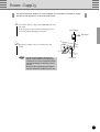
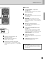
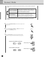
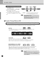
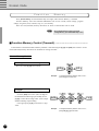
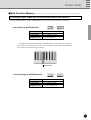
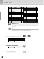
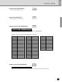
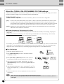
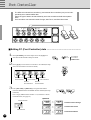
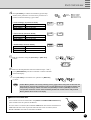
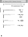
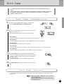
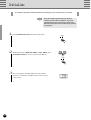
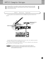
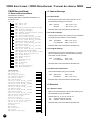
STATUS
DATA/CTRL
2
BANK MSB/MAX
BANK LSB/MIN
TOGGLE ON-OFF
/NUMBER OF PGM
DEC ±10 INC
/NO
/YES
MEMORY
EDIT
FC
EDIT
WRITE
/EXIT
Congratulations!
Thank you for purchasing Yamaha’s MFC10 MIDI Foot Controller.
The MFC10 is a versatile MIDI foot control device that can transmit program changes and
control changes to control effectors, tone generators, keyboards, MIDI guitars, rhythm
machines, etc..
In addition to the onboard foot controller, up to 4 optional external foot controllers or
switches can also be connected to the MFC10 for increased control versatility.
In order to make full use of the MFC10’s features and functions, we recommend that you
read this manual thoroughly and keep it in a safe place for future reference.
Contents
Precautions ................................................................................................................... 2
Power Supply ............................................................................................................... 3
Nomenclature ............................................................................................................... 4
Functions du MFC10 .................................................................................................... 6
2 Modes ..................................................................................................... 6
Foot Controller Settings ................................................................................... 7
All memory MIDI Channel Assign ........................................................................ 7
Bulk Dump .................................................................................................. 7
Normal Mode ................................................................................................................ 8
Program Change Memory
................................................................................. 9
Program Change Memory Control (Transmit) .......................................................... 9
Program Change Memory Edit ......................................................................... 10
Function Memory ........................................................................................... 12
Function Memory Control (Transmit) .................................................................. 12
Edit Function Memory ................................................................................... 13
About the TOGGLE ON-OFF/NUMBER OF PGM settings ................................. 18
MIX Mode .................................................................................................................... 19
MIX Mode Memory Control (Transmit) ................................................................ 20
Editing MIX mode ........................................................................................ 21
The MIX mode’s Function Memory ............................................................ 21
Foot Controller ........................................................................................................... 22
...................................................................... 22
All Memory MIDI Channel Number Assign............................................................... 24
Bulk Dump .................................................................................................................. 25
Bulk Dump (Transmission) .............................................................................. 25
Bulk Dump (Receive) ..................................................................................... 25
Initialize ....................................................................................................................... 26
MFC10 Sample Setups ............................................................................................... 27
MIDI Guitar System ........................................................................................ 27
MIDI Keyboard System ................................................................................... 28
MIDI Effector System ..................................................................................... 28
MIDI Sequencer or Rhythm Programmer System ................................................. 29
Error Messages .......................................................................................................... 30
Trouble Shooting ........................................................................................................ 30
Editing FC (Foot Controller) data
MIDI Implementation Chart .......................................................................................................
MIDI data format .......................................................................................................................
Operation Guide ........................................................................................................................
Program Table ...........................................................................................................................
Specifications ............................................................................................................................
31
32
35
36
40
1
Precautions
!! PLEASE READ THIS BEFORE PROCEEDING !!
■ Location
Do not expose the MFC10 to the following
conditions to avoid deformation, discoloration,
or more serious damage.
• Direct sunlight (e.g. near a window).
• High temperatures (e.g. near a heat source,
outside, or in a car during the daytime).
• Excessive humidity.
• Excessive dust.
• Strong vibration.
■ USE THE CORRECT POWER SUPPLY
• Power to the MFC10 should be supplied
only from the appropriate Yamaha AC
adaptor (the PA-3B or another adaptor
specifically recommended by Yamaha). Use
of another adaptor may cause serious
damage to the unit. Also make sure that the
adaptor you have is appropriate for the AC
mains supply voltage in the area where you
intend to use the MFC10. (The correct
input voltage is marked on the adaptor.)
■ Power Supply
• Turn the power switch OFF when the
instrument is not in use.
• The power adaptor should be unplugged
from the AC outlet if the MFC10 is not to
be used for an extended period of time.
• Unplug the MFC10 during electric storms.
• Avoid plugging the MFC10 into the same
AC outlet as appliances with high power
consumption, such as electric heaters or
ovens. Also avoid using multi-plug adaptors
since these can result in reduced sound
quality and possibly damage.
■ Turn Power OFF When Making Connections
• To avoid damage to the MFC10 and other
devices to which it is connected (a sound
system, for example), turn the power
switches of all related devices OFF prior to
connecting or disconnecting audio and MIDI
cables.
■ MIDI Connections
• When connecting the MFC10 to MIDI
equipment, be sure to use high-quality
cables made especially for MIDI data
transmission.
• Avoid MIDI cables longer than about 15
meters. Longer cables can pick up electrical
noise that can causes data errors.
■ Handling and Transport
• Never apply excessive force to the controls,
connectors or other parts of the instrument.
• Always unplug cables by gripping the plug
firmly, not by pulling on the cable.
• Disconnect all cables before moving the
instrument.
• Physical shocks caused by dropping,
bumping, or placing heavy objects on the
instrument can result in scratches and more
serious damage.
■ Cleaning
• Clean the cabinet and panel with a dry soft
cloth.
• A slightly damp cloth may be used to
remove stubborn grime and dirt.
• Never use cleaners such as alcohol or
thinner.
• Avoid placing vinyl objects on top of the
instrument (vinyl can stick to and discolor
the surface).
■ Electrical Interference
• This instrument contains digital circuitry
and may cause interference if placed too
close to radio or television receivers. If this
occurs, move the instrument further away
from the affected equipment.
■ Data Backup
• The MFC10 contains a special read-write
memory without a battery, that retains the
contents of its internal memory even when
the power is turned OFF.
■ Service and Modification
• The MFC10 contains no user serviceable
parts. Opening it or tampering with it in any
way can lead to irreparable damage and
possibly electric shock. Refer all servicing
to qualified YAMAHA personnel.
YAMAHA is not responsible for damage caused by improper handling or operation.
2
Power Supply
Use the PA-3B power adaptor (or another adaptor recommended by Yamaha) to supply
the MFC10 with power from a convenient wall socket.
1
Connect the adaptor’s plug into the [DC IN] jack on the
rear panel.
Wrap the power cord around the cord stopper hook to
prevent accidental unplugging during use.
Power Adaptor
Wall Socket
2
Plug the AC adaptor into any convenient AC wall
socket.
• Do not use an AC adaptor other than the
PA-3B, or other adoptors recommended by
Yamaha. The use of any incompatible adaptor
may result in damage, overheating, or fire to
the unit.
• Be sure to disconnected the power adaptor
from the outlet when the MFC10 is not in use.
POWE
R
ON/
OFF
DC IN
Cord Stopper
3
Nomenclature
Front Panel
2
1
STATUS
DATA/CTRL
BANK MSB/MAX
BANK LSB/MIN
TOGGLE ON-OFF
/NUMBER OF PGM
4 3
8.8.8.
DEC ±10 INC
/NO
/YES
5 6
MEMORY
EDIT
FC
EDIT
7
WRITE
/EXIT
8
9
0
Rear Panel
POWER
ON/ OFF
DC IN
FOOT CONTROLLER 1
5
FOOT
CONTROLLER/SWITCH
4
3
^
MIDI
2
OUT
%
IN
* &
$
■ Front Panel
1 Parameter Lamp (see page 11, 16)
The currently selected parameter lamp will flash when
in the edit mode.
2 LED Display (see page 6)
Memory numbers, program changes and functions
(control changes) saved in memory, parameters, etc.,
are indicated in the display.
3 [INC/YES] (see page 11, 17)
Increases (INC) edit number values in the Play mode
and parameter data values in the Edit mode, and to
save data that has been edited, the YES button is used
to confirm the save operation.
4 [DEC/NO] (see page 11, 17)
Decreases (DEC) edit number values in the Play mode
and parameter data values in the Edit mode, and when
confirmation of the save operation of edited data is
requested, the NO button cancels the save operation.
4
WX IN
5 [MEMORY EDIT] (see page 11, 16)
Enters the Memory Edit mode and selects edit parameters.
6 [FC EDIT] (see page 22)
Enters the Foot Controller Edit mode and selects edit
parameters.
7 [WRITE/EXIT] (see page 11, 17)
Exits the Edit mode and returns to the Normal control
mode. At this time it is necessary to press the [INC/
YES] button or [DEC/NO] button to either confirm or
cancel the data overwrite operation.
8 [FUNCTION] Foot switch (see page 6)
Switches between Program Change Memory and
Function Memory when in the Normal Mode.
In the Mix Mode, switches between Mix mode and
Function Memory.
* When the lamp above the [FUNCTION] foot switch
is lit, the MFC10 is in Function Memory.
Nomenclature
!
■ Rear Panel
@ [FUNCTION NORMAL — MIX] Switch
(see page 8, 19)
Selects the mode that the MFC10 is to be operated in,
Normal mode or Mix mode.
# [MIDI — WX] Switch
Selects whether MIDI data is received via the WX jack
or the MIDI IN jack.
$ [WX IN] Jack
A Yamaha Wind MIDI Controller WX7/11 can be
directly connected to this jack. (The MFC10 supplies
electric power to the WX7/11, so the BT-7 Power Box is
not needed.)
% [MIDI IN/OUT] Jacks (see page 27)
Using a MIDI cable, external MIDI devices can be
connect to the MFC10.
^ [FOOT CONTROLLER/SWITCH 2-5] Jacks
(see page 22)
WX
FUNCTION
NORMAL — MIX
#
@
MIDI
These jacks allow the connection of up to 4 optional
foot controllers or foot switches to the MFC10. The
connected foot controllers or foot switches can be used
to control MIDI data in the same manner as the
onboard foot controller.
& [DC IN] Jack (see page 3)
9 [1]-[0] Foot switch (see page 9, 12)
Selects Memory Numbers.
0 [x10] Foot switch (see page 9, 12)
Select the 100's or 10's digit.
Connect the power adaptor here to supply the MFC10
with power.
* [POWER ON/OFF] Switch (see page 8)
Turns the MFC10’s power on or off.
! Onboard Foot Controller (see page 22)
The Foot Controller can be used to transmit control
changes, after touch, pitch bend, etc., to external MIDI
devices.
User Memo Sticker
The supplied User Memo Sticker can be applied
next to the number plate above each foot switch to
write memos on.
5
MFC10 Functions
When a foot switch is pressed, MIDI data (program changes/function data) stored in the
MFC10’s internal memory is transmitted to external MIDI devices.
• Program Change Data
Program change data transmitted from the MFC10 can select
voices, etc., on other MIDI devices.
Bank select data can be transmitted along with program change
data as well.
• Function Data
The MFC10 can transmit the following function data to control
other MIDI devices.
• NOTE ON/OFF (90-9F)
• CONTROL CHANGE (b0-bF)
• PROGRAM CHANGE (C0-CF)
• SONG SELECT (F3)
• START (FA)
• CONTINUE (Fb)
• STOP (FC)
• SECTION CONTROL (F0)
• TEMPO CONTROL (Ft)
* Values in parentheses are shown in the display.
■ 2 Modes ................................................................................................
The MFC10’s foot switches can be set to operate in one of two modes (Normal Mode/Mix Mode). Use the
[FUNCTION NORMAL — MIX] switch on the rear panel to set the mode the MFC10 will operate in. (see
page 5, 8, 19)
How the foot switches operate in each mode is further explained below.
• NORMAL mode
[In this mode, Program Change Memory and Function Memory are independent of each other.]
FUNCTION
NORMAL — MIX
Program change memory
(128 types)
STATUS
DATA/CTRL
BANK MSB/MAX
BANK LSB/MIN
TOGGLE ON-OFF
/NUMBER OF PGM
Function memory
(100 types)
STATUS
DATA/CTRL
DEC ±10 INC
/NO
/YES
MEMORY
EDIT
FC
EDIT
WRITE
/EXIT
BANK MSB/MAX
BANK LSB/MIN
TOGGLE ON-OFF
/NUMBER OF PGM
DEC ±10 INC
/NO
/YES
MEMORY
EDIT
FC
EDIT
WRITE
/EXIT
Switch
Function lamp is off
6
Function lamp is lit
MFC10 Functions
• MIX mode
[In this mode, Program Change Memory and Function Memory are mixed.]
FUNCTION
NORMAL — MIX
Upper level foot switches [6]-[0]
Function memory (5 types)
F06
F00
STATUS
DATA/CTRL
BANK MSB/MAX
BANK LSB/MIN
TOGGLE ON-OFF
/NUMBER OF PGM
DEC ±10 INC
/NO
/YES
MEMORY
EDIT
FC
EDIT
WRITE
/EXIT
Program change memory
(5 x 5 types)
11
15
Lower level foot switches [1]-[5]
11 ~15 , 21 ~ 25 , 31 ~ 35 , 41 ~ 45 , 51 ~ 55
• To access all 100 (F00-F99) Function Memory types, press
the [FUNCTION] switch, and it’s lamp will light.
• In the MIX mode, Program Change memory (25 memories)
is stored and played independent of Program Change
memory in the NORMAL mode.
■ Foot Controller Settings .....................................................................
Sets parameters for the onboard Foot Controller and the external Foot Controllers 2-5. (see page 22)
■ All Memory MIDI Channel Number Assign........................................
The settings for all MIDI channels, in all assigned memories, can be set to the same MIDI channel. (see page 24)
■ Bulk Dump ...........................................................................................
Internal data for the Normal mode Program Change Memory, the Mix mode Program Change Memory, and
Function Memory and Foot Controller Memory (1-5) can be transmitted via MIDI OUT. (see page 25)
7
Normal Mode
Both Program Change Memory and Function Memory can be accessed in the Normal
Mode.
Program Change Memory
There are 128 memory allocations for Program
Change data. By selecting a memory number, its
stored program change is transmitted to external
devices via the MIDI OUT terminal.
Function Memory
There are 100 memory allocations for Function data
(control change etc.). By selecting a memory
number, its stored function data is transmitted to
external devices via the MIDI OUT terminal.
Press the [FUNCTION] to switch between Program Change Memory and Function
Memory.
1
Press the [POWER ON/OFF] switch on the rear panel to turn
the power on.
2
Set the [FUNCTION NORMAL—MIX] switch on the rear
panel to the [NORMAL] position.
3
Press [FUNCTION] to switch between Program Change
Memory (see page 9) and Function Memory (see page 12).
• Program Change Memory (128 types)
001 ~
Function lamp is off.
128
• Function Memory (100 types)
Function lamp is lit.
F00 ~
8
F99
POWER
ON/ OFF
FUNCTION
NORMAL — MIX
Normal Mode
Program
Change
Memory
If FUNCTION lamp is lit, press [FUNCTION], so that the lamp is off, and Program Change Memory
is enabled.
Program Change Memory transmits MIDI channel numbers 1-16 and program change data (001-128)
that are stored in memory.
There are 128 memory allocations in which Program Change data can be saved. Also, Bank
Select data (00=MSB, 20=LSB) can be transmitted along with Program Change data.
• Press [FUNCTION] to enable Function Memory
(the FUNCTION lamp lights).
■ Program Change Memory Control (Transmit) ..................................
Program changes and bank select data are transmitted when a memory number is selected with the [1]-[0]
and [x10] foot switches. A total of 128 (001-128) memory allocations are available for storing such data.
Select a Memory Number
STATUS
DATA/CTRL
BANK MSB/MAX
BANK LSB/MIN
TOGGLE ON-OFF
/NUMBER OF PGM
8.88
. .
DEC ±10 INC
/NO
/YES
MEMORY
EDIT
FC
EDIT
WRITE
/EXIT
[1]-[0], [x10] foot switches
To change or select the 1's digit.
Press one of the [1]-[0] foot switches.
084
Example:
081
To change the current memory number
084 to 081 press [1] once.
To change and select both the 10's and
1's digits.
Press [x10]. (The 10's digit of the LED
flashes indicating input standby.) Press [1]-[0], to
select the 10's digit value. (The 1's digit flashes
indicating input standby.)
Once again press [1]-[0] to select the 1's digit
value.
023
Example:
082
To change the current Memory Number
023 to 082, press [x10], [8], and [2] in
that order.
9
Normal Mode
To change and select all digits.
Press [x10] two times.
If the 100's digit value is 1, it will change to
0, if it is 0 it will change to 1. (The 10's digit
flashes indicating input standby.)
Press [1]-[0], to select the 10's digit value.
(The 1's digit flashes indicating input standby.)
Once again, press [1]-[0] to select the 1's digit
value.
048
126
Two times
Example:
To change the current Memory Number 048 to
126, press [x10], [X10], [2], [6] in that order.
• When [x10] is pressed twice, the 100's digit value will
alternate between 1 and 0.
• Attempting to select the number 000, will result in 001
being selected. Also, inputting any value above 128
will result in 128 being selected.
■ Program Change Memory Edit...........................................................
The following 4 types of MIDI data can be transmitted with Program Change Memory.
The transmitting Channel Number and MIDI data can be stored to individual Memory Numbers.
• STATUS
C0
~
CF
Cn (n=MIDI channel numbers 1-16) assigns the MIDI channel for voice selection. The
number is shown in hexadecimal.
C0
C1
C2
C3
Channel 1
Channel 2
Channel 3
Channel 4
C4
C5
C6
C7
Channel 5
Channel 6
Channel 7
Channel 8
• DATA/CTRL
C8
C9
CA
Cb
Channel 9
Channel 10
Channel 11
Channel 12
001 ~
CC
Cd
CE
CF
Channel 13
Channel 14
Channel 15
Channel 16
128
Sets program numbers (voice numbers 001-128) for transmission.
Refer to the owner's manual of the receiving device for details on voice assignments.
Refer to a GM voice map for the 128 voice allocations of GM MIDI devices.
• BANK MSB (Bank Select MSB)
• BANK LSB (Bank Select LSB)
oFF , 000 ~
127
Bank select numbers are used to access voices other than the 128 voices normally available in
MIDI devices and GM devices. Program change data and bank select data (BANK MSB/
LSB:off, 000-127) must be transmitted together to access these voices.
Refer to the owner's manual of the receiving device for specific information on bank select data.
• The default settings for each memory (001-128) is as
follows.
STATUS=C0 (Channel Number 1), DATA/CTRL=001-128
(same as the memory number), BANK MSB/MAX=off,
BANK LSB/MIN=off.
10
Normal Mode
How to Edit Memory
If the FUNCTION lamp is lit, press [FUNCTION], so that the
lamp is off, and Program Change Memory is enabled.
1
Select the Memory Number to be edited (see page 9). Press
[MEMORY EDIT] to edit to begin editing that Memory
Number. (The lamp above that foot switch and the STATUS
lamp will flash.)
MEMORY
EDIT
2
Press [MEMORY EDIT] to cycle through the 4 edit parameters (the selected parameter’s light will flash).
• TOGGLE ON-OFF/NUMBER OF PGM can not be
selected from Program Change Memory.
MEMORY
EDIT
STATUS settings
STATUS
DATA/CONTROL settings
DATA/CTRL
BANK MSB/MAX BANK MSB settings
BANK LSB settings
BANK LSB/MIN
TOGGLE ON-OFF
/NUMBER OF PGM
3
Use [INC/YES] and [DEC/NO] to edit the parameter.
Press [INC/YES] to increase the value shown in the LED
display by 1, press [DEC/NO] to decrease the value by 1. By
holding a button, values will continuously increase or decrease.
Hold the [INC/YES] button and press the [DEC/NO] button
and the value shown in the LED display will increase by 10.
Repeatedly press [DEC/NO] to continue increasing the value
by 10.
Hold the [DEC/NO] button and press the [INC/YES] button
and the value shown in the LED display will decrease by 10.
Repeatedly press [INC/YES] to continue decreasing the value
by 10.
001
128
128
001
DEC ±10 INC
/NO
/YES
DEC ±10 INC
/NO
/YES
DEC ±10 INC
/NO
/YES
Increase by 10
Decrease by 10
DEC ±10 INC
/NO
/YES
4
After the desired parameters have been edited in steps 2 and 3,
press [WRITE/EXIT]. The Memory Number shown in the
LED display will flash. (The flashing number indicates
confirmation is necessary to proceed or cancel saving of the
edited data.)
WRITE
/EXIT
007
• If data has not been edited, the Memory Number will
not flash and the MFC10 will return to its normal
control mode.
5
Press [INC/YES], to save the edited data to the current
Memory Number, The MFC10 will return to its normal control
mode.
Press [DEC/NO] to cancel the save operation of the edited
data. At this time the memory will revert to its pre-edited
contents.
DEC ±10 INC
/NO
/YES
DEC ±10 INC
/NO
/YES
• Another Memory Number from the same bank (10’s digit bank) can be easily edited by
pressing [1] - [0] without exiting from the edit mode. You must execute or cancel the save
operation for the currently edited data (the current Memory Number will flash) before
proceeding to edit the new number. Use [INC/YES] to execute or [DEC/NO] to cancel the
save operation. If data has not been edited, the Memory Number will not flash and the
newly selected Memory Number will be shown in the display.
11
Normal Mode
Function
Memory
Press [FUNCTION], the FUNCTION lamp will light, and Function Memory is enabled.
Function Memory stores and transmits MIDI data such as note on/off, control change, program
change, song select, start, continue, stop, etc., in its memory.
There are 100 (F00-F99) memory allocations in which Function Data can be saved.
• Press [FUNCTION] to enable to Program
Change Memory. (The FUNCTION lamp is off.)
■ Function Memory Control (Transmit) ................................................
Function data is transmitted when a Memory Number is selected using the [1]-[0] and [x10] foot switches. A total
of 100 (F00-F99) memory allocations are available for storing such data.
Select a Memory Number
To change and select the 1's digit.
Press one of the [1]-[0] foot switches.
F84
Example:
F81
To change the Memory Number “F84” to “F81”
press the [1] foot switch once.
To change and select both the 10's and
1's digits.
Press the [x10] foot switch. (The 10's digit of
the LED flashes indicating input standby.) Press
[1]-[0], to select the 10's digit value. (The 1's digit
flashes indicating input standby.)
Once again press [1]-[0] to select the 1's digit
value.
F23
Example:
12
F47
To change the Memory Number “F23” to “F47”,
press [x10], [4], [7] in that order.
Normal Mode
■ Edit Function Memory ........................................................................
The following 9 types of MIDI data can be transmitted with Function Memory.
The transmitting Channel Number and MIDI data can be stored to individual Memory Numbers.
~
90
• Note On/Off (9) [STATUS=90-9F]
DATA/CTRL
BANK MSB/MAX
BANK LSB/MIN
TOGGLE ON-OFF
/NUMBER OF PGM
9F
000-127 (Note Number)
001-127 (Note On Velocity)
001-127 (Note Off Velocity)
Pn1-Pn4 (see page 18)
Transmits keyboard Note On/Off data. If a different note is set to each foot switch, the
foot switches can be used to play a scale. Also, if a sampler is connected to the MFC10 the
foot switches can be used to trigger samples.
54
56
58
61
63
66
68
70
C3
........ 53
55
57
59
60
62
64
65
67
69
71 ........
Note Number
• Control Change (b) [STATUS=b0-bF]
DATA/CTRL
BANK MSB/MAX
BANK LSB/MIN
TOGGLE ON-OFF
/NUMBER OF PGM
b0
~
bF
000-127 (Control Number)
000-127 (Switch On Data)
000-127 (Switch Off Data)
off, on, Pn1-Pn4 (see page 18)
13
Normal Mode
Control Change List (for GM, XG supported devices)
Control
Number
0
1
5
6
7
10
11
32
38
64
65
66
67
71
72
73
74
GENERAL
Function
Bank Select
Modulation
Portamento Time
Data Entry
Main Volume
Pan Pot
Expression
Bank Select
Data Entry
Hold 1 (Damper Pedal)
Portamento
Sostenuto (Chord Hold)
Soft Pedal
Harmonic Content
Release Time
Attack Time
Brightness
GM XG
N
Y
N
Y
Y
Y
Y
N
Y
Y
N
N
N
N
N
N
N
Y
Y
Y
Y
Y
Y
Y
Y
Y
Y
Y
Y
Y
Y
Y
Y
Y
84
91
93
94
96
97
98
99
100
101
120
121
122
123
124
125
126
127
Portamento Control
Extensive Use Effect 1 (Reverb)
Extensive Use Effect 3 (Chorus)
Extensive Use Effect 4 (Celeste)
Data-Increment
Data-Decrement
NRPN(LSB)
NRPN(MSB)
RPN(LSB)
RPN(MSB)
All Sound Off
Reset All Controllers
Local Control
All Note Off
Omni Off
Omni On
Mono On
Poly On
Y...Yes
N
N
N
N
N
N
N
N
Y
Y
N
Y
N
Y
N
N
N
N
Y
Y
Y
Y
Y
Y
Y
Y
Y
Y
Y
Y
Y
Y
Y
Y
Y
Y
N...No
GM (GM System Level 1)
[GM] (General MIDI is in addition to the MIDI standard which ensures that any GM-compatible
music data can be accurately played on any GM-compatible tone generator, regardless of the
maker. The GM mark is affixed to all software and hardware products that support the General
MIDI standard.
XG
[XG] is a MIDI format created by Yamaha which significantly imporves and expands upon the
General MIDI standard by providing a greater variety of high-quality Voices plus considerably
enhanced effect operations—while being fully compatible with GM.
• Program Change (C) [STATUS=C0-CF]
DATA/CTRL
BANK MSB/MAX
BANK LSB/MIN
TOGGLE ON-OFF
/NUMBER OF PGM
001-128 (Program Number)
off, 000~127
off, 000~127
Pn1-Pn4 (see page 18)
• Song Select (F3) [STATUS=F3]
DATA/CTRL
F3
000-127 (Song Number)
• Start (FA) [STATUS=FA]
Other parameters cannot be set.
14
C0
FA
~
CF
Normal Mode
• Continue (Fb) [STATUS=Fb]
Fb
Other parameters cannot be set.
FC
• Stop (FC) [STATUS=FC]
Other parameters cannot be set.
F0
• Section Control (F0) [STATUS=F0]
DATA/CTRL
BANK MSB/MAX
c01-c42 (Section Number)
01-16, - - - (Device Number)
* When c41 or c42 is selected, the device number must be set in BANK MSB/MAX.
Data for section types that can be transmitted are listed below.
c01
Intro 1
c17
Fill In AA1
c33
Ending 1
c02
Intro 2
c18
Fill In AA2
c34
Ending 2
c03
Intro 3
c19
Fill In AA3
c35
Ending 3
c04
Intro 4
c20
Fill In AA4
c36
Ending 4
c05
Intro 5
c21
Fill In AA5
c37
Ending 5
c06
Intro 6
c22
Fill In AA6
c38
Ending 6
c07
Intro 7
c23
Fill In AA7
c39
Ending 7
c08
Intro 8
c24
Fill In AA8
c40
Ending 8
c09
Main 1
c25
Fill In AB1
c41
Reset Start
c10
Main 2
c26
Fill In AB2
c42
Stop & Rewind
c11
Main 3
c27
Fill In AB3
c12
Main 4
c28
Fill In AB4
c13
Main 5
c29
Fill In AB5
c14
Main 6
c30
Fill In AB6
c15
Main 7
c31
Fill In AB7
c16
Main 8
c32
Fill In AB8
• Tempo Control (Ft) [STATUS=Ft]
DATA/CTRL
Ft
030~250 (Tempo Value)
The tempo of external devices can be controlled within a range of 30-250 beats per minute.
15
Normal Mode
How to Edit Memory
1
Select the Function Memory to be edited, press [MEMORY
EDIT], to begin editing that memory number. (The lamp above
the foot switch and the STATUS lamp will flash.)
STATUS
DATA/CTRL
BANK MSB/MAX
BANK LSB/MIN
TOGGLE ON-OFF
/NUMBER OF PGM
MEMORY
EDIT
2
Press [INC/YES] and [DEC/NO] to select the Status (transmit
MIDI data and MIDI channel number) (the STATUS lamp will
flash).
The 1's digit (MIDI channel number 1-16) of Status is shown in
hexadecimal. (see page 10)
DEC ±10 INC
/NO
/YES
DEC ±10 INC
/NO
/YES
Channel number
90
90...9F
b0...bF
CO...CF
F3
FA
Fb
FC
FO
Ft
Transmit Note On/Off
MIDI data
Transmit Control Change
Transmit Program Change
Transmit Song Select
Transmit Start
Transmit Continue
Transmit Stop
Transmit Section Control
Transmit Tempo Control
3
Press [MEMORY EDIT] to select the parameters set in the
procedures above for editing (the lamp will flash).
STATUS
DATA/CTRL
BANK MSB/MAX
BANK LSB/MIN
TOGGLE ON-OFF
/NUMBER OF PGM
Note On/Note Off
STATUS
(0-F indicates MIDI channel numbers)
DATA/CTRL
BANK MSB/MAX
BANK LSB/MIN
TOGGLE ON-OFF
/NUMBER OF PGM
STATUS
DATA/CTRL
BANK MSB/MAX
BANK LSB/MIN
TOGGLE ON-OFF
/NUMBER OF PGM
16
Control Change
MEMORY
EDIT
Program Change
90-9F
b0-bF
C0-CF
Note Number
Note On Velocity
Note Off Velocity
Control Number
Switch On Data
Switch Off Data
Toggle On/Off
Pn1-Pn4
Program Number
Bank MSB
Bank LSB
Pn1-Pn4
Pn1-Pn4
Song Select
F3
0-127
–
–
Start
FA
–
–
–
Continue
Fb
–
–
–
Stop
FC
–
–
–
–
–
–
–
Normal Mode
STATUS
DATA/CTRL
BANK MSB/MAX
BANK LSB/MIN
TOGGLE ON-OFF
/NUMBER OF PGM
Section Control
F0
c01 - c42
Channel Number (if c41, c42 is used)
–
Tempo Control
Ft
030- 250
–
–
–
–
*(—) is displayed to indicate parameters that cannot be selected.
4
Press [INC/YES] or [DEC/NO] to edit parameter values.
Press [INC/YES] to increase the value shown in the LED
display by 1, press [DEC/NO] to decrease the value by 1. By
holding a button, values will continuously increase or decrease.
DEC ±10 INC
/NO
/YES
Hold the [INC/YES] button and press the [DEC/NO] button
and the value shown in the LED display will increase by 10.
Repeatedly press [DEC/NO] to continue increasing the value
by 10.
DEC ±10 INC
/NO
/YES
001
128
128
001
Increase by 10
DEC ±10 INC
/NO
/YES
Hold the [DEC/NO] button and press the [INC/YES] button
and the value shown in the LED display will decrease by 10.
Repeatedly press [INC/YES] to continue decreasing the value
by 10.
Decrease by 10
DEC ±10 INC
/NO
/YES
5
After the desired parameters have been edited in steps 3 and 4,
press [WRITE/EXIT]. The Memory Number shown in the
LED display will flash.
F07
WRITE
/EXIT
• If data has not been edited, the Memory Number will
not flash and the MFC10 will return to its normal
control mode.
6
Press [INC/YES], to save the edited data to the current
Memory Number, The MFC10 will return to its normal control
mode.
Press [DEC/NO] to cancel the save operation of the edited
data. At this time the memory will revert to its pre-edited
condition.
DEC ±10 INC
/NO
/YES
DEC ±10 INC
/NO
/YES
• Another Memory Number from the same bank (10’s digit bank) can be easily edited by pressing [1] - [0]
without exiting from the edit mode. You must execute or cancel the save operation for the currently
edited data (the current Memory Number will flash) before proceeding to edit the new number. Use [INC/
YES] to execute or [DEC/NO] to cancel the save operation. If data has not been edited, the Memory
Number will not flash and the newly selected Memory Number will be shown in the display.
17
Normal Mode
About the TOGGLE ON-OFF/NUMBER OF PGM settings.
TOGGLE ON-OFF/NUMBER OF PGM contains the settings for “on, off, Pn1, Pn2, Pn3, Pn4”. According to the setting, you can use the
foot switch to operate as a toggle on-off, or simultaneously transmit several MIDI data.
TOGGLE ON-OFF settings
TOGGLE ON-OFF settings can be used in Function Memory that are saved with control change data.
• [on]...... Press the foot switch and the MAX value (switch on data) is continuously transmitted. Press the foot switch
once again and the MIN value (switch off data) is transmitted. The foot switch’s lamp will flash from the
time the MAX value is transmitted, until the MIN value is transmitted. Even if another foot switch is pressed,
the lamp will remain flashing. (The flashing lamp indicates continuous transmission of the MAX value.)
• [oFF].... Hold the foot switch and the MAX value (switch on data) is transmitted. Release the foot switch and the
MIN value (switch off data) is transmitted.
MIDI Data Simultaneous Transmission (Pn1-Pn4)
Pn1-Pn4 settings can be used in Function Memory that are saved with Note ON/OFF, control change, and program
change data.
Within Function Memories F00-F49, up to 4 of the same type of MIDI data (one of the following— Note On/Off,
Control Change, Program Change) can be simultaneously transmitted.
F00
Pn4 Pn3
Pn2
F01
F49
Pn4 Pn3
Pn2
Pn1
Pn4 Pn3
Pn2
Pn1
Pn1
For example, you can transmit several note on/off data over the same MIDI channel to play chords, or transmit control
change data over several MIDI channels to simultaneously control external effectors. Also, you can simultaneously
change the voices of several devices by transmitting Program Change Data over several MIDI channels.
■ Pn1-Pn4 Settings
STATUS
DATA/CTRL
BANK MSB/MAX
BANK LSB/MIN
TOGGLE ON-OFF
/NUMBER OF PGM
1 Select the memory number to be set.
MEMORY
EDIT
2 Press [MEMORY EDIT] and select “TOGGLE ON-OFF/
NUMBER OF PGM”.
3 Press [INC/YES] or [DEC/NO] and select “Pn1” (“Pn1” is
automatically selected when the edit operation is entered).
DEC ±10 INC
/NO
/YES
DEC ±10 INC
/NO
/YES
Pn1
4 Select each parameter (STATUS, DATA/CTRL, etc.) using
[MEMORY EDIT], and set as required using [INC/YES] and
[DEC/NO].
5 After setting all parameters for “Pn1”, repeat steps 2 and 3 to
select “Pn2”. Repeat step 4 to select and set each parameter as
MEMORY
EDIT
Pn2
required.
6 In the same manner as “Pn2”, set parameters for “Pn3”, and “Pn4”
if necessary.
• When “Pn1-Pn4” is set, the toggle setting will automatically be set to ON.
• If data is stored in Memory Numbers F00-F49, “Pn1” will automatically be selected when the Memory Number is
edited again.
18
MIX Mode
In the MIX mode, both Program Change data and Function data can be accessed at the
same time without having to change between modes with the [FUNCTION] switch. This
mode provides quick transmission of Program Change data and Function data.
In this mode, up to 25 different Program memories (independent of the NORMAL mode)
can be saved and accessed from the lower level of foot switches [1]-[5], and up to 5
different Function memories can be saved and accessed from the upper level of foot
switches [6]-[0]. Each of those memories can be selected and transmitted with the [1]-[0]
and [x10] foot switches.
1
Set the [FUNCTION NORMAL-MIX] switch on the
rear panel to the [MIX] position.
FUNCTION
NORMAL — MIX
2
Press [FUNCTION] and turn off the FUNCTION
lamp.
If [FUNCTION] is pressed while in the MIX mode
(the FUNCTION lamp lights), the MIX mode’s
FUNCTION memory (see page 21) will be enabled. All
foot switches can access the MFC10’s 100 FUNCTION
memories.
The 10's digit setting is valid when the MFC10 is
returned to the MIX mode. Press [FUNCTION] once
again, the FUNCTION lamp turns off, and the MFC10
is returned to MIX mode.
* The contents of each Function Memory number is same data between NORMAL mode and MIX mode. Program
Change Memory exists independently in each mode.
* Default setting for Program Change Memory in the MIX mode.
11[C0, 00], 12[C0, 01], 13[C0, 02], 14[C0, 03], 15[C0, 04], 21[C0, 05], 22[C0, 06], ...
19
MIX Mode
■ MIX Mode Memory Control (Transmit) ..............................................
In the MIX mode, a maximum of 25 Program Change memories (independent in this mode) and 5 Function memories can be stored in memory and later transmitted via MIDI.
• Use the upper level foot switches [6]-[0] to transmit Function data.
F16 ~
F10
Pressing [6]-[0] transmits Function data.
To select the Function number’s 10's digit, press [FUNCTION], and the MIX mode will switch
to the MIX mode’s Function Memory (see page 21). In this state, all foot switches ([0]-[9]) will
transmit Function Memory.
STATUS
DATA/CTRL
BANK MSB/MAX
BANK LSB/MIN
TOGGLE ON-OFF
/NUMBER OF PGM
DEC ±10 INC
/NO
/YES
MEMORY
EDIT
FC
EDIT
WRITE
/EXIT
• Use the lower level foot switches [1]-[5] to transmit Program Change data.
11
~
15
11~15, 21~25, 31~35, 41~45, 51~55
Press [1]-[5] to access the 25 (5 x 5) Program Change Memories.
To select the Program Change Memory number’s 10's digit, press [x10], next press [1]-[5] to
enter a value of 1-5.
Program Memory data can be edited in the same manner as the Normal mode, press [MEMORY
EDIT] to begin editing.
• Only 2 digits (10’s digit and 1’s digit) are displayed for
Program Change memory numbers in the MIX mode.
20
MIX Mode
■ Editing MIX mode ................................................................................
With the MFC10 in MIX mode control status, press the [MEMORY EDIT] button.
• Editing Program Change Memory
To edit the data in the 25 memory types (independent in this mode) for foot switches [1] - [5], can be
edited using the same procedure to edit Program Change Memory when in the Normal mode. (see page
10)
• Editing Function Memory
To edit the data in the 5 memory types for foot switches [6] - [0], can be edited using the same procedure to edit Function Memory when in the Normal mode. (see page 13)
The MIX mode’s Function Memory
In the MIX mode, press [FUNCTION], the FUNCTION lamp lights, and the MFC10 is switched to the
MIX mode’s function memory. It is also possible to select the Function memory number’s 10 value.
Press [FUNCTION], the lamp turns off, and the MFC10 returns to the MIX mode.
Function Memory
(10 x 10 types)
Function Memory
(5 types)
F06
F00
STATUS
DATA/CTRL
STATUS
DATA/CTRL
BANK MSB/MAX
BANK LSB/MIN
TOGGLE ON-OFF
/NUMBER OF PGM
DEC ±10 INC
/NO
/YES
MEMORY
EDIT
FC
EDIT
Program Change Memory
(5 x 5 types)
11
BANK MSB/MAX
BANK LSB/MIN
TOGGLE ON-OFF
/NUMBER OF PGM
DEC ±10 INC
/NO
/YES
MEMORY
EDIT
FC
EDIT
WRITE
/EXIT
WRITE
/EXIT
Switch
15
• Function Memory Control in the MIX mode
Function Memory Control in the MIX mode is the same operation as in the Normal Mode (see page 12).
• Editing Function Memory in the MIX mode
Editing Function Memory in the MIX mode is the same operation as in the Normal Mode (see page 13).
21
Foot Controller
The MFC10’s onboard foot controller (1) and external foot controllers (2-5) can be independently set to transmit MIDI data.
Select the type of data to be transmitted by each foot controller and edit those parameters.
Foot controllers can transmit Control Change, After Touch, and Pitch Bend data.
STATUS
DATA/CTRL
BANK MSB/MAX
BANK LSB/MIN
TOGGLE ON-OFF
/NUMBER OF PGM
8.88
. .
DEC ±10 INC
/NO
/YES
MEMORY
EDIT
FC
EDIT
WRITE
/EXIT
■ Editing FC (Foot Controller) data ......................................................
1
Press [FC EDIT], one of the lamps above the [1]-[5] foot
switches and the STATUS lamp will flash.
STATUS
DATA/CTRL
FC
EDIT
BANK MSB/MAX
BANK LSB/MIN
TOGGLE ON-OFF
/NUMBER OF PGM
2
Press [1]-[5] to select the foot controller to be edited (the lamp
above the selected foot switch will flash).
Onboard
Foot Controller 1
External
Foot Controller 3
External
Foot Controller 2
External
Foot Controller 5
External
Foot Controller 4
3
Press [INC/YES] or [DEC/NO] to assign STATUS data
(transmit MIDI STATUS and MIDI channel number)(the lamp
will flash).
The 1's digit (MIDI channel number 1-16) of Status is shown
in hexadecimal. (see page 10)
DEC ±10 INC
/NO
/YES
DEC ±10 INC
/NO
/YES
● STATUS
Channel Number
d3
b0 ~
bF
Transmit Control Change
d0 ~
dF
Transmit After Touch
E0 ~
EF
Transmit Pitch Bend
MIDI STATUS
22
Foot Controller
4
Press [FC EDIT], to edit the selected data type (the lamp
flashes) of the parameters set in the above procedure. It is
possible to edit the following types of data.
• Control Change (b) [STATUS=b0-bF]
DATA/CTRL
BANK MSB/MAX
BANK LSB/MIN
bF
d0 ~
dF
E0 ~
EF
BANK MSB/MAX
BANK LSB/MIN
TOGGLE ON-OFF
/NUMBER OF PGM
–––
000-127 MAX Value
000-127 MIN Value
• Pitch Bend (E) STATUS=E0-EF]
DATA/CTRL
BANK MSB/MAX
BANK LSB/MIN
~
b0
001-031, 033-120 Control Number
000-127 MAX Value
000-127 MIN Value
• After Touch (d) [STATUS=d0-dF]
DATA/CTRL
BANK MSB/MAX
BANK LSB/MIN
STATUS
DATA/CTRL
FC
EDIT
–––
000-127 Pitch Bend MAX
000-127 Pitch Bend MIN*
* The value of the Pitch Bend’s center pitch is 64.
5
Edit the parameters using the [INC/YES] or [DEC/NO]
buttons.
DEC ±10 INC
/NO
/YES
DEC ±10 INC
/NO
/YES
FC1
6
After the desired parameters have been edited in steps 4 and 5,
press [WRITE/EXIT]. The Foot Controller’s number will flash
in the LED display.
7
Press [INC/YES] to execute the save operation or [DEC/NO]
to cancel.
DEC ±10 INC
/NO
/YES
DEC ±10 INC
/NO
/YES
• Another Memory Number can be easily edited by pressing [1]-[5] without exiting from the edit mode. You
must execute or cancel the save operation for the currently edited data (the current Memory Number will
flash) before proceeding to edit the new number. Use [INC/YES] to execute or [DEC/NO] to cancel the
save operation. If data has not been edited, the Memory Number will not flash and the newly selected
Memory Number will be shown in the display.
■ About Foot Switch Use
Foot switches can also be connected to the [FOOT CONTROLLER/SWITCH 2-5]
jacks located on the rear panel of the MFC10.
If a foot switch is connected, the set BANK MSB/MAX value will be transmitted via
MIDI when the foot switch is pressed. When the foot switch is released, the set
BANK LSB/MIN value will be transmitted via MIDI.
23
All Memory MIDI Channel Assign
The MIDI channel settings for all assigned memories can be set to the same MIDI channel, setting all MIDI channels to the same channel can be convenient in some situations.
• Pressing [INC/YES] in the operation will change all
memory MIDI channel assignments!
1
For both Normal and MIX mode operation, simultaneously
press both [MEMORY EDIT] and [FC EDIT].
The MIDI channel number will be shown in the LED display
MEMORY
EDIT
FC
EDIT
WRITE
/EXIT
C01
2
Press [INC/YES] or [DEC/NO] to select the new channel
number (C01-C16) for all memories.
DEC ±10 INC
/NO
/YES
DEC ±10 INC
/NO
/YES
C09
3
Press [WRITE/EXIT].
The channel number in the LED display will flash.
WRITE
/EXIT
C09
4
Press [INC/YES] to confirm the setting of all channels, or
[DEC/NO] to cancel the operation.
24
DEC ±10 INC
/NO
/YES
DEC ±10 INC
/NO
/YES
Bulk Dump
The MFC10’s internal settings can be transmitted to an external MIDI data storage
device.
Using a device such a Yamaha’s MIDI Data Filer MDF2, the MFC10’s data can be saved
to, as well as loaded from such a device. The bulk dump operation is convenient for
keeping important data.
Bulk
Dump
(Transmission)
1
For both Normal and MIX mode operation, simultaneously
press both [MEMORY EDIT] and [WRITE/EXIT].
MEMORY
EDIT
FC
EDIT
WRITE
/EXIT
bL1
2
Press the corresponding foot switch to select one of the 5 bulk
dump types listed below.
The selected bulk dump type will flash in the LED display.
bL3
• Foot switch [1]
All data listed the 4 bulk dump types that follow will be transmitted.
• Foot switch [2]
All data for Program Change Memory in the NORMAL mode will be transmitted.
• Foot switch [3]
All data for Function Memory will be transmitted.
• Foot switch [4]
Set data for the onboard Foot Controller 1 and External Foot Controllers 2-5 will be transmitted.
• Foot switch [5]
All data for Program Change Memory in the MIX mode will be transmitted.
3
Press [INC/YES] and the selected data will be immediately
transmitted via MIDI to the external device. Once the operation
is complete, “End” will appear in the display, and the MFC10
will return to step 2.
Press [WRITE/EXIT] to cancel the Bulk Dump operation.
DEC ±10 INC
/NO
/YES
4
Press [WRITE/EXIT] to return the MFC10 to normal control
status.
Bulk
Dump
WRITE
/EXIT
(Receive)
In the normal control status or edit status, the MFC10 can receive bulk dump transmissions from an
external device.
• Make sure the [MIDI — WX] switch on the rear panel is
set to the MIDI position.
• Normal operation of the MFC10 is not possible during
bulk dump operations.
25
Initialize
The initialize operation restores the MFC10’s settings to their original factory condition.
• Using the initialize operation will erase whatever
settings you have made on the MFC10. If you have
important settings you wish to keep, store them to a
MIDI data storage device with the Bulk Dump operation
(see page 25)
1
Press [POWER ON/OFF] and switch off the power.
POWER
ON/ OFF
2
While holding both [MEMORY EDIT] and [FC EDIT], press
[POWER ON/OFF] to switch on power to the MFC10.
MEMORY
EDIT
FC
EDIT
POWER
ON/ OFF
3
“FA” will appear in the LED display once the initialize
operation is completed. The MFC10 will return to normal
control status.
26
FA
MFC10 Sample Setups
Using the MFC10, it is possible to transmit Program Change data and Function data
without using your hands. Also, external devices can be cued or controlled smoothly
without the loss of a beat.
MIDI
Guitar
System
A guitar synthesizer system (Yamaha G50+G1D etc.) and MIDI tone generator connected to the
MFC10.
MIDI Tone Generator
YAMAHA MU50,
VL1-m version 2,
VL70-m, etc.
MIDI IN
MIDI Guitar
TAR
GUI
MIX TH
SYN
N
DOW
VOL
UP
Guitar Synthesizer
System
Guitar with Yamaha G1D,
etc., attached.
MIDI OUT
POWER
PARAMETER
MIDI CH
(MONO/POLY) TUNER
DIVIDED
MONO SYNTH
PARAMETER
MEMORY#/VALUE
NO
GUITAR SETUP
INPUT
LEVEL
PLAY
MEMORY# / VALUE
PARAMETER
SELECT
–1
YES
+1
±10
WRITE
EXTERNAL TG SETUP
H PROGRAM CHANGE #
A PLAYING STYLE
I
BANK MSB
B NOTE ON LEVEL
J
BANK LSB
C NOTE OFF LEVEL
K VOLUME
D VELO CITY
L PAN
E CHROMATIC
M ASSIGNABLE 1
F TRANSPOSE
VALUE
G PITCH BEND RANGE N
O ASSIGNABLE 2
P
VALUE
REALTIME CONTROL
Q SPLIT
R
MEMORY2#
S
MEM2 LOCATION
T PICKING CONTROL
U
FRONT
V
REAR
W TOUCH CONTROL
X
SENSITIVITY
Y SUSTAIN/HOLD PEDAL
ON/
OFF
MIDI IN
Guitar MIDI Converter
Yamaha G50, etc.
MIDI OUT
STATUS
DATA/CTRL
BANK MSB/MAX
BANK LSB/MIN
TOGGLE ON-OFF
/NUMBER OF PGM
8.8.8.
DEC ±10 INC
/NO
/YES
MEMORY
EDIT
PC
EDIT
WRITE
/EXIT
Program changes transmitted by the MFC10 can be used to select voices (MIDI tone generator
voices) that are currently set in the guitar MIDI converter.
Also, Function data transmitted by the MFC10 can be used to manipulate control change data
that are currently set in the guitar MIDI converter.
Setting
Both the MIDI converter’s receive channel number and the MFC10’s
Program Change Memory Status (MIDI channel number) should be set to
the same MIDI channel number.
27
MFC10 Sample Setups
MIDI
Keyboard
System
Connect the MFC10 to a MIDI keyboard (Yamaha Synthesizer VL1/VL7, W5/W7, QS300, EOS,
Portable Keyboard, Clavinova, etc.).
MIDI IN
MIDI OUT
STATUS
DATA/CTRL
BANK MSB/MAX
BANK LSB/MIN
TOGGLE ON-OFF
/NUMBER OF PGM
8.8.8.
DEC ±10 INC
/NO
/YES
MEMORY
EDIT
PC
EDIT
WRITE
/EXIT
Keyboard
Yamaha VL1/VL7, W5/W7, etc.
The currently set keyboard voices (MIDI tone generator voices) can be changed, according to
the type of Program Change data transmitted from the MFC10.
Also, control change data, etc., set in the keyboard can be controlled according to the type
Function data transmitted from the MFC10. Rhythm or song start/stop, continue, etc., can also be
controlled depending on the type of instrument.
Setting
Both the MIDI keyboard’s receive channel number and the MFC10’s
Program Change Memory Status (MIDI channel number) should be set to
the same MIDI channel number.
MIDI
Effector
System
MIDI effectors (Yamaha SPX990, etc.) connected to the MFC10 can receive MIDI program changes.
MIDI OUT
STATUS
DATA/CTRL
BANK MSB/MAX
BANK LSB/MIN
TOGGLE ON-OFF
/NUMBER OF PGM
8.8.8.
DEC ±10 INC
/NO
/YES
MEMORY
EDIT
PC
EDIT
WRITE
/EXIT
MIDI IN
Effector
Yamaha SPX990, etc.
According to the Program Change data transmitted from the MFC10, set Program Change numbers
with the corresponding effect program (type) to select that effect. Of course you can select effects with
the effector itself, but using the MFC10 leaves your hands free to play yet, provides the ability to select
effects quickly and easily.
Setting
28
Both the MIDI effector’s receive channel number and the MFC10’s Program Change Memory Status (MIDI channel number) should be set to the
same MIDI channel number.
MFC10 Sample Setups
MIDI Sequencer
Programmer
or Rhythm
System
• Connect the MFC10 to a sequencer (Yamaha QY300, QY22, QY8, etc.) or rhythm
programmer (Yamaha RY20, RY8, etc.).
The sequencer/rhythm programmer’s start/continue/stop, etc., can be controlled according to Function
data transmitted from the MFC10.
MIDI OUT
STATUS
DATA/CTRL
BANK MSB/MAX
BANK LSB/MIN
TOGGLE ON-OFF
/NUMBER OF PGM
8.8.8.
DEC ±10 INC
/NO
/YES
MEMORY
EDIT
PC
EDIT
MIDI IN
WRITE
/EXIT
QY300
MUSIC SEQUENCER
Sequencer/rhythm programmer
Yamaha QY300, RY20, etc.
Setting
Both the MIDI sequencer or rhythm programmer’s receive channel number and
the MFC10’s Memory Status (MIDI channel number) should be set to the same
MIDI channel number.
Also, the MFC10 does not transmit a timing clock so the sequencer or rhythm
programmer’s clock should be set to [Internal].
• Connect a keyboard and the MFC10, the MFC10 and a sequencer or rhythm
programmer.
As the keyboard’s MIDI signal runs through the MFC10, the MFC10 can add function data
(section control data, etc.). The MFC10’s data is then merged with keyboard data and transmitted
to the sequencer or rhythm programmer.
MIDI IN
MIDI OUT
STATUS
DATA/CTRL
BANK MSB/MAX
BANK LSB/MIN
TOGGLE ON-OFF
/NUMBER OF PGM
8.8.8.
DEC ±10 INC
/NO
/YES
MEMORY
EDIT
PC
EDIT
WRITE
/EXIT
Keyboard
MIDI OUT
Yamaha VL1/VL7, W5/W7, etc.
MIDI IN
QY300
MUSIC SEQUENCER
Sequencer/
Rhythm Programmer
Yamaha QY300, RY20, etc.
Setting
Both the MIDI keyboard’s transmit channel number and the MFC10’s
Program Change Memory Status (MIDI channel number) and the sequencer/rhythm programmer’s receive channel number should be set to
the same MIDI channel number.
Also, the MFC10 does not transmit a timing clock (MIDI signals received by
the MFC10 will be sent directly to the MIDI OUT terminal) so the
keyboard’s clock should be set to [Internal] and the sequencer/rhythm
programmer’s clock should be set to [External].
29
Error Message List
Should an error occur while using the MFC10, one of the following messages will appear
in the LED display. Press [WRITE/EXIT] to return the MFC10 to its normal play mode. (In
the case of error message 5, the internal memory may have some MISS, pressing
[WRITE/EXIT] will automatically initialize the internal memory.)
Er1
MIDI Receive Error. An error has occurred during reception of data.
–>Check the transmitting device and try again.
Er2
MIDI Bulk Data Error. An error has been detected in the MIDI data received.
–>Check the transmitting device and try again.
Er3
MIDI Line Error. After FE has been received, Note On data has been received
but, no MIDI data was received within a 350 msec interval.
–>Check the cable and the condition of the transmitting device.
Er4
MIDI IN Buffer Error. A MIDI buffer overflow has occurred.
–>Reduce the volume of data being transmitted or transmit the data in
smaller blocks.
Er5
Try pressing [WRITE/EXIT] button. If "Er5" appear again, Memory Data Error.
An error has occurred in the internal memory. The device may need repair.
–>Take the device to your nearest Yamaha dealer for further evaluation.
Trouble Shooting
Problem
30
Cause/Solution
Program changes do not transmit.
Check the mode, is it in NORMAL mode or MIX
mode? (see page 6,7)
Foot Controller data does not transmit.
Check the MAX and MIN setting. (see page 23)
Cannot set TOGGLE ON-OFF.
Is Program Change Memory active? TOGGLE ONOFF cannot be set in Program Change Memory.
Also, TOGGLE ON-OFF can only be set in the
Function Memory’s control change.
The MFC10 does not receive MIDI data and/or Bulk
data.
Check the [MIDI—WX] switch on the rear panel. It
should be set to the MIDI position.
MIDI Implementation Chart / MIDI-Implementierungstabelle /
Table d’implémentation MIDI
YAMAHA
[MIDI Foot Controller]
Date:31-MAY-1996
Model MFC10 MIDI Implementation Chart
Version : 1.00
+----------------------------------------------------------------------+
:
: Transmitted
:
Recognized
:
Remarks
:
:
Function ... :
:
:
:
:-------------------+----------------+----------------+----------------:
:Basic
Default
: 1-16
: 1-16
: memorized
:
:Channel Changed
: 1-16
: 1-16
:
:
:-------------------+----------------+----------------+----------------:
:
Default
: x
: x
:
:
:Mode
Messages : o
: OMNIon,OMNIoff :
:
:
:
: POLY,MONO
:
:
:-------------------+----------------+----------------+----------------:
:Note
: 0-127
: 0-127
:
:
:Number : True voice: ************** :
:
:
:-------------------+----------------+----------------+----------------:
:Velocity Note ON
: o 9nH,v=1-127 : o
:
:
:
Note OFF : o 8nH,v=1-127 : o
:
:
:-------------------+----------------+----------------+----------------:
:After
Key's
: x
: o
:
:
:Touch
Ch's
: o
: o
:
:
:-------------------+----------------+----------------+----------------:
:Pitch Bender
: o
: o
:
:
:-------------------+----------------+----------------+----------------:
:
0-121 : o
: o
:
:
:
:
:
:
:
:
:
:
:
:
:
:
:
:
:
: Control
:
:
:
:
:
:
:
:
:
: Change
:
:
:
:
:
:
:
:
:
:
:
:
:
:
:
:
:
:
:
:
:
:
:
:
:
:
:
:
:
:-------------------+----------------+----------------+----------------:
:Prog
: o 0-127
: o 0-127
:
:
:Change : True #
:
:
:
:
:-------------------+----------------+----------------+----------------:
:System Exclusive
: o
: o
:
:
:-------------------+----------------+----------------+----------------:
:System : Song Pos. : x
: o
:
:
:
: Song Sel. : o
: o
:
:
:Common : Tune
: x
: o
:
:
:-------------------+----------------+----------------+----------------:
:System
:Clock
: x
: o
:
:
:Real Time :Commands: o
: o
:
:
:-------------------+----------------+----------------+----------------:
:Aux :Local ON/OFF : o
: o
:
:
:
:All Notes OFF: x
: x
:
:
:Mes- :Active Sense : o
: o
:
:
:sages:Reset
: x
: o
:
:
:-------------------+----------------+----------------+----------------:
:Note
: Received messages from MIDI IN are only bypassed :
:
: to MIDI OUT.
:
+-------------------+----------------+----------------+----------------+
Mode 1 : OMNI ON, POLY
Mode 2 : OMNI ON, MONO
o : Yes
Mode 3 : OMNI OFF, POLY
Mode 4 : OMNI OFF, MONO
x : No 31
MIDI data format / MIDI-Datenformat / Format des donées MIDI
1 MIDI Receive/Send
1.2 Channel Message
1.1 Receive/Send conditions
<MIDI Receive conditions>
1.2.1 Note On/Off
Following MIDI data is transmitted via the MIDI OUT
exception for “FE”.
MIDI IN
$8n (Note Off)
$9n (Note On)
$An
(Poly Key Pressure/After Touch)
$Bn (Control Change)
$Cn (Program Change)
$Dn (Chnnel Pressure/After Touch)
$En (Pitch Bend)
$F0 (System Exclusive)
$F0 43 00 7A bb bb LM__0271PG
(Program Change Memory Bulk)
$F0 43 00 7A bb bb LM__0271FN
(FUNCTION Memory Bulk)
$F0 43 00 7A bb bb LM__0271FC
(FC Memory Bulk)
$F0 43 00 7A bb bb LM__0271AL
(All Memory Bulk)
$F0 43 00 7A bb bb LM__0271MX
(MIX Program Change Bulk)
$F1 (MIMI Time Code Quater Frame)
$F2 (Song Position Pointer)
$F3 (Song Select)
$F6 (Tune Request)
$F7 (EOX)
$F8 (Timing Clock)
$FA (Start)
$FB (Continue)
$FC (Stop)
$FE (Active Sensing)
$FF (System Reset)
Following stored data in the Function memory can be
transmitted by pressing the Foot Switch.
data:
Note On
Note Off
= $9n, 0-127, 1-127
= $8n, 0-127, 1-127
Received data is also transmitted via the MIDI OUT.
1.2.2 Control Change
Following data in the Function memory can be transmitted
by pressing the Foot Switch or Foot Controller.
data:
Foot Switch
Foot Controller
=$Bn, 0-127, 0-127
=$Bn, 0-120, 0-127
Received data is also transmitted via the MIDI OUT.
1.2.3 Program Change
Stored data in the Program Change Memory or Function
Memory (following data) can be transmitted by pressing
Foot Switch or Foot Controller.
data:
Foot Switch
Foot Controller
=$Cn, 0-127
=$Cn, 0-120
Received data is also transmitted via the MIDI OUT.
1.2.4 After Touch .Pitch Bend
<MIDI Transmit>
Can be transmitted by using Foot Controller
$8n (Note Off)
$9n (Note On)
$Bn (Control Change)
$Cn (Program Change)
$Dn (After Touch)
$En (Pitch Bend)
$F0 43 00 7A bb bb LM__0271PG
(Program Change Memory Bulk)
$F0 43 00 7A bb bb LM__0271FN
(FUNCTION Memory Bulk)
$F0 43 00 7A bb bb LM__0271FC
(FC Memory Bulk)
$F0 43 00 7A bb bb LM__0271AL
(All Memory Bulk)
$F0 43 00 7A bb bb LM__0271MX
data:
=$Dn, 0-127
=$En, 0-127, 0-127
Received data is also transmitted via the MIDI OUT.
1.3 Exclusive
1.3.1 Section Control
Section control data (stored in the Function Memory) can
be transmitted by using Foot Switch.
(MIX Program Change Bulk)
$F0 43 7E 00 ss dd
(Section Control)
$F0 43 6n 7A (Reset Start)
$F0 43 6n 7D (Stop & Rewind)
$F0 43 7E 01 t4 t3 t2 t1
(Tempo Control)
$F7 (EOX)
$FA (Start)
$FB (Continue)
$FC (Stop)
$FE (Active Sensing)
Transmit data: F0, 43, 7E, 00, SS, DD, F7
SS:
Section Number 00-27 [Hex]
DD:
ON/OFF (ON=7F, OFF=00)
Received data is also transmitted via the MIDI OUT.
MIDI OUT
32
After Touch
Pitch Bend
1.3.2 Start/Stop Control
1.5.3 Status byte FE
Start/Stop control data (stored in the Function Memory)
can be transmitted by using Foot Switch.
data:
Reset Start
Stop & Rewind
=F0, 43, 6n, 7A, F7
=F0, 43, 6n, 7D, F7
FE (active sensing) is transmitted in 255 msec steps.
If no data is received within 350 msec from the first
reception of FE, the MFC10 will stop FE data transmission within 500 msec.
Received data is also transmitted via the MIDI OUT.
1.3.3 Tempo Control
Tempo data (stored in the Function Memory) can be
transmitted by using Foot Switch.
Transmit data=F0, 43, 7E, 01, t4, t3, t2, t1, F7
Received data is also transmitted via the MIDI OUT.
1.4 System Common Message
1.4.1 Status byte F1, F2, F3, F6
F1, F2, F3 and F6 can only be received
F1:
Time Chord
F2:
Song Position pointer
F3:
Song Select
F6:
Tune Request
Received data is also transmitted via the MIDI OUT.
1.5 System Realtime Message
1.5.1 Status byte F8, FF
F8 or FF Status can only be received
F8:
Timing Clock
FF:
System Reset
Received data is also transmitted via the MIDI OUT.
2 Bulk dump
Bulk dump can be received in the both Play and Edit
mode.
The contents of the Program memory, Function memory
or Foot Controller can be transmitted.
Dump request does not receive.
2.1 All memory data bulk dump
0
1
2
3
4
5
6
7
8
9
10
11
12
13
14
15
16
:
31
32
:
1.5.2 Status byte FA, FB, FC
Stored data FA, FB or FC in the Function memory can be
transmitted by pressing the Foot Switch.
FA:
Start
FB:
Continue
FC:
Stop
Received data is also transmitted via the MIDI OUT.
11110000
01000011
00000000
01111010
0bbbbbbb
0bbbbbbb
01001100
01001101
00100000
00100000
00110000
00110010
00110111
00110001
01000001
01001100
00000000
:
00000000
0ddddddd
:
0sssssss
11110111
F0
43
00= Device Number(Fixed)
7A
BB= Byte Count
BB
4C(ascii”L”)
4D(ascii”M”)
20(ascii” ”)
20(ascii” ”)
30(ascii”0”)
32(ascii”2”)
37(ascii”7”)
31(ascii”1”)
41(ascii”A”)
4C(ascii”L”)
00
:
00
DD= Data
:
SS= Check Sum
F7
Overwrites to the Program Change, Function, Foot Controller memory when data is received.
2.2 Normal Mode Program memory data
bulk dump
0
1
2
3
4
5
6
7
8
11110000
01000011
00000000
01111010
0bbbbbbb
0bbbbbbb
01001100
01001101
00100000
F0
43
00= DeviceNumber(Fixed)
7A
BB= Byte Count
BB
4C(ascii”L”)
4D(ascii”M”)
20(ascii” ”)
33
MIDI data format / MIDI-Datenformat / Format des données
9
10
11
12
13
14
15
16
:
31
32
:
00100000
00110000
00110010
00110111
00110001
01010000
01000111
00000000
:
00000000
0ddddddd
:
0sssssss
11110111
20(ascii” ”)
30(ascii”0”)
32(ascii”2”)
37(ascii”7”)
31(ascii”1”)
50(ascii”P”)
47(ascii”G”)
00
:
00
DD= Data
:
SS= Check Sum
F7
Overwrites to the Program Change memory when data is
received.
8
9
10
11
12
13
14
15
16
:
31
32
:
00100000
00100000
00110000
00110010
00110111
00110001
01000110
01000011
00000000
:
00000000
0ddddddd
:
0sssssss
11110111
20(ascii” ”)
20(ascii” ”)
30(ascii”0”)
32(ascii”2”)
37(ascii”7”)
31(ascii”1”)
46(ascii”F”)
43(ascii”C”)
00
:
00
DD= Data
:
SS= Check Sum
F7
Overwrites to the Foot Controller memory when data is
received.
2.3 Function memory data bulk dump
0
1
2
3
4
5
6
7
8
9
10
11
12
13
14
15
16
:
31
32
:
11110000
01000011
00000000
01111010
0bbbbbbb
0bbbbbbb
01001100
01001101
00100000
00100000
00110000
00110010
00110111
00110001
01000110
01001110
00000000
:
00000000
0ddddddd
:
0sssssss
11110111
F0
43
00= Device Number(Fixed)
7A
BB= Byte Count
BB
4C(ascii”L”)
4D(ascii”M”)
20(ascii” ”)
20(ascii” ”)
30(ascii”0”)
32(ascii”2”)
37(ascii”7”)
31(ascii”1”)
46(ascii”F”)
4E(ascii”N”)
00
:
00
DD= Data
:
SS= Check Sum
F7
Overwrites to the Function memory when data is received.
2.4 Foot Controller memory data bulk
dump
0
1
2
3
4
5
6
7
34
11110000
01000011
00000000
01111010
0bbbbbbb
0bbbbbbb
01001100
01001101
F0
43
00= Device Number(Fixed)
7A
BB= Byte Count
BB
4C(ascii”L”)
4D(ascii”M”)
2.5 Mix Mode Program memory data bulk
dump
0
1
2
3
4
5
6
7
8
9
10
11
12
13
14
15
16
:
31
32
:
11110000
01000011
00000000
01111010
0bbbbbbb
0bbbbbbb
01001100
01001101
00100000
00100000
00110000
00110010
00110111
00110001
01001101
01011000
00000000
:
00000000
0ddddddd
:
0sssssss
11110111
F0
43
00= DeviceNumber(Fixed)
7A
BB= Byte Count
BB
4C(ascii”L”)
4D(ascii”M”)
20(ascii” ”)
20(ascii” ”)
30(ascii”0”)
32(ascii”2”)
37(ascii”7”)
31(ascii”1”)
4D(ascii”M”)
58(ascii”X”)
00
:
00
DD= Data
:
SS= Check Sum
F7
Overwrites to the Program Change memory when data is
received.
Operation Guide / Bedienungsführer / Guide des opérations
NORMAL mode
Program Chamge Memory
EDIT
MEMORY
EDIT
Function lamp is off
FUNCTION
NORMAL — MIX
Function Memory
EDIT
MEMORY
EDIT
Function lamp is lit
MIX mode
Function Memory
+
Program Chanege Memory
FUNCTION
NORMAL — MIX
EDIT
MEMORY
EDIT
Function lamp is off
Function Memory
MEMORY
EDIT
EDIT
Function lamp is lit
Others
All memory MIDI channel Assign
MEMORY
EDIT
FC
EDIT
MEMORY
EDIT
WRITE
/EXIT
Bulk Dunp
POWER
ON/ OFF
Initia Lize
MEMORY
EDIT
FC
EDIT
35
Program Table / Programmübersicht / Tableau de programmes
NORMAL mode
DATA:
NAME:
●Program Change
Program Number:
1~
0
6
7
8
9
0
1
2
3
4
5
STATUS
DATA/CTRL
BANK MSB
BANK LSB
STATUS
DATA/CTRL
BANK MSB
BANK LSB
●Function
Function Number: F
1~F
0
6
NUMBER OF PGM
STATUS
DATA/CTRL
MAX
MIN
TOGGLE ON-OFF
1
2
NUMBER OF PGM
STATUS
DATA/CTRL
MAX
MIN
TOGGLE ON-OFF
1
2
7
3
4
1
2
3
4
1
2
1
8
3
4
1
2
3
4
1
2
2
9
3
4
1
2
3
4
1
2
3
0
3
4
1
2
3
4
1
2
4
1
36
2
3
4
4
3
4
5
●Foot Controller
STATUS
DATA/CTRL
MAX
MIN
3
5
MIX mode
DATA:
NAME:
Function Number: F
6~F
0
6
NUMBER OF PGM
STATUS
DATA/CTRL
MAX
MIN
TOGGLE ON-OFF
1
2
7
3
Program Number:
4
1
2
8
3
1~
4
1
2
9
3
4
1
2
0
3
4
1
2
3
4
0
1
2
3
4
5
1
2
3
4
5
STATUS
DATA/CTRL
BANK MSB
BANK LSB
●Foot Controller
STATUS
DATA/CTRL
MAX
MIN
* Make copies of sheet to keep records of your MFC10 settings.
* Machen Sie sich zum Eintragen der MFC10-Einstellungen Kopien von diesem Blatt.
* Faites des copies de ces feuilles pour conserver les réglages de votre MFC10.
37
Program Table / Programmübersicht / Tableau de programmes
NORMAL mode
DATA:
NAME:
●Program Change
Program Number:
1~
0
6
7
8
9
0
1
2
3
4
5
STATUS
DATA/CTRL
BANK MSB
BANK LSB
STATUS
DATA/CTRL
BANK MSB
BANK LSB
●Function
Function Number: F
1~F
0
6
NUMBER OF PGM
STATUS
DATA/CTRL
MAX
MIN
TOGGLE ON-OFF
1
2
NUMBER OF PGM
STATUS
DATA/CTRL
MAX
MIN
TOGGLE ON-OFF
1
2
7
3
4
1
2
3
4
1
2
1
8
3
4
1
2
3
4
1
2
2
9
3
4
1
2
3
4
1
2
3
0
3
4
1
2
3
4
1
2
4
1
38
2
3
4
4
3
4
5
●Foot Controller
STATUS
DATA/CTRL
MAX
MIN
3
5
MIX mode
DATA:
NAME:
Function Number: F
6~F
0
6
NUMBER OF PGM
STATUS
DATA/CTRL
MAX
MIN
TOGGLE ON-OFF
1
2
7
3
Program Number:
4
1
2
8
3
1~
4
1
2
9
3
4
1
2
0
3
4
1
2
3
4
0
1
2
3
4
5
1
2
3
4
5
STATUS
DATA/CTRL
BANK MSB
BANK LSB
●Foot Controller
STATUS
DATA/CTRL
MAX
MIN
* Make copies of sheet to keep records of your MFC10 settings.
* Machen Sie sich zum Eintragen der MFC10-Einstellungen Kopien von diesem Blatt.
* Faites des copies de ces feuilles pour conserver les réglages de votre MFC10.
39
Specifications / Technische Daten / Spécifications
40
Program Change Memory
Normal:128, Mix:25
Function Memory
100
Mode
Normal, Mix
Foot Controllers1
(Onboard Foot Controller)
2-5 (External Foot Controllers)
Other
MIDI IN -> MIDI OUT (MERGE Transmit)
WX11 etc., Controller Connection
MIDI Bulk Dump (Transmit and Receive)
Control
Foot Switch x12, Onboard Foot Controller x1,
Panel Switch x5, LED Display, Power Switch,
MIDI IN/WX IN Switch, Function Normal/Mix
Switch
ConnectorsExternal
Foot Controller Jacks x4, MIDI IN/OUT Terminals, WX IN Terminal, DC IN Jack
Supplied Accessories
Owner's Manual, User Memo Sticker
Dimensions (mm)
608 (23-15/16") x 215 (8-1/2") x 153 (6")
Weight (kg)
3.52 (7Ibs 12oz)