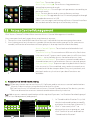
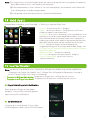
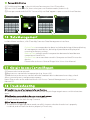
1
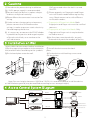
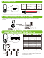
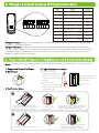
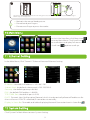
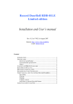
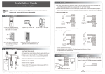
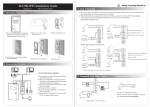
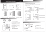
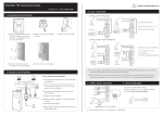
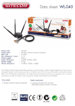
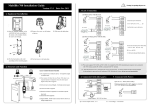
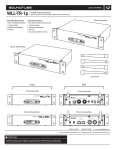
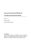
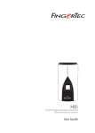
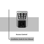
Finger Vein Access Control dvice Quick Start Guide Version: 1.0 Date: June 2015 1 Overview Fingerprint & Finger Vein Device Front Left Side: Touch screen USB slot Doorbell Fingerprint reader Reset button: Press the button (with sharp-headed tool with less than 2 mm in diameter) after 30second powering-on to reset device. Finger vein reader Finger vein sensor: During registration, after finger touches the sensor, device begins collecting and verifying fingerprint and finger vein. Rese Finger Vein Device Card reader Left Side Front Touch screen USB slot Card reader Doorbell Reset button: Press the button (with sharp-headed tool with less than 2 mm in diameter) after 30-second powering-on to reset device. Finger vein reader Finger vein sensor: During registration, after finger touches the sensor, device begins collecting and verifying finger vein. } Power Input GND +12V Back NC } Lock 1 AL- COM1 NC1 BUT SEN GND BELL- BELL+ GND RJ45-3 RJ45-6 GND 485A 485B RJ45-1 RJ45-2 } Alarm Common Doorbell NO } } } Open/Close -door button NO1 Door sensor } AUX WD1 } } Wiegand RS485 Output Auxiliary Input AL+ IWD0 IWD1 12V GND } } Power Output Tamper Alarm Switch WD0 } E thernet Wiegand Input 2 Cautions ①Shut down the power during installation. ② 12V/3A power supply is recommended. ③Do not install the device in a place subject to direct sunlight or humidity. ④Please follow the connector instruction for wiring. ⑤ Under serious electrostatic environment, please connect the GND before other wirings, in order to prevent static electricity from damaging the device. ⑥ It is necessary to connect the FR107 diodes in parallel to the positive and negative poles of the electrical lock, so as to release the self-inductance EMF generated when the lock is turned ON/OFF. ⑦ Please properly set fingerprint and finger vein verification mode before registering users. Requirement varies with different verification modes: » Fingerprint & Finger Vein Mode: Both fingerprint and finger vein must be verified to access. » Fingerprint or Finger Vein Mode: Only fingerprint or finger vein is required to be verified to access. ⑧the functions mentioned with are only featured with particular models of device. 3 Installation on Wall Insert cables to connectors before installation. ①Put the mounting template sticker onto the wall, and drill holes according to the symbols. ③ Install the device onto the back plate. ④Fix the device with locking screws onto the back plate. ②Fix the back plate onto the wall. A Mounting Template Bottom View A Back Plate C B C B Note: For user heights between 150CM to 170CM, it is recommended to install the device at 140CM above ground (may be modified according to user average height). 4 Access Control System Diagram RS485 Siren RS485 Alarm USB Drive Server Open/Close -door button TCP/IP Lock Door Sensor Door 2 5 Power Connection PIN +12V GND Slot Color 1 Power Input +12V Red 2 Ground GND Black 1 +12V DC GND 2 The operation power of the device shall be DC12V, the current shall be 3A. 6 Connection to Computer softwares via Ethernet Connection between device and computer (Access control software) via Ethernet. Shown as below: IP Address: 192.168.1.39 Subnet Mask: 255.255.255.0 IP Address: 192.168.1.201 Subnet Mask: 255.255.255.0 7 Connection to Doorbell, Door Sensor, Open/Close Door Button, Alarm & Siren etc. Slot AL+ COM1 AL- NO1 NC1 SEN GND BUT GND BELL- BELL+ Brown 3 Ground GND Purple Doorbell BELL- 4 Green Doorbell BELL+ Orange Yellow Door Sensor SEN GND 8 Ground Open/Close Door Button Normal Open 9 Common Door Sensor 10 Normal Closed NC1 Grey 11 Alarm AL- Black 12 Alarm + % - AL- COM1 NC1 BUT BUT NO1 White COM1 black AL+ Red AL+ - Power Alarm + Doo rbell Red Blue Device can be connected via Auxiliary Input Slot with output switch signal sensors including siren, gas detector, infrared detector and emergency switch. + Open/Close Door Button - + NO1 + Siren GND BELL- 7 Power SEN - - GND 2 Color AUX 5 - AUX Auxiliary Input 6 + Power 1 BELL+ AUX PIN 3 8 Wiegand Input/Output Wiring Instruction Slot 485B 485A GND WD1 WD0 IWD1 GND IWD0 12V PIN Color 1 Power Output 2 Ground GND Black 3 Wiegand Input IWD0 White 4 Wiegand Input IWD1 Green 5 Wiegand Output WD0 Blue Red +12V 6 Wiegand Output WD1 Yellow 7 Ground GND Black 8 RS485 485A Grey 9 RS485 485B Purple Wiegand Input: the device is featured with Wiegand signal input function to connect to card reader or standalone device. Wiegand Output: the device is featured with standard Wiegand signal output function and can be used as reader. The wiring distance between device to controller should not exceed 5m (if longer connection distance or connection with strong interference are necessary, please adopt Wiegand signal exteneder). 9 Finger Vein & Fingerprint Registration and Verification Modes Note: In finger vein registration process, the fingerprint of the selected finger is also registered. 1. Suggested finger: first finger, middle finger 3. Verification Steps 2. Finger Placement Position ①In order to read your fingerprint and finger vein data, touch the front side of finger vein reader with fingertip, ②The device starts collecting data once the finger root touches the finger vein reader. ① Finger pr int R eader Finger Vein Reader Finger Guide ② Touch Sensor ① Touch the front side of finger vein reader with fingertip, then press your finger upon the finger vein reader. Place the finger according to the finger guide. Finger-tip must touch the front of finger vein reader in order to properly collect fingerprint and finger vein images. ② Improper positioning of finger will affect the proper collection of fingerprint and finger vein images. Touch the reader with finger root. 4 ③ The device starts collecting data once the finger root touches the finger vein reader. Remove finger after “beep” sound appears. » Maintain the natural hand gesture. » Do not bend your fingers. » Do not exert finger to press the reader. 10 Main Menu In the initial interface, click Menu icon to enter Main Menu. Click Scroll icon to scroll down to display full menu. Click Scroll icon again to scroll up. 11 Ethernet Setting In the Main Menu, Click “Comm”>”Ethernet” to enter Ethernet Setting. IP Address: the default IP address is 192.168.1.201. Subnet Mask: the default subnet mask is 255.255.255.0. Gateway: the default gateway is0.0.0.0. DNS: the default DNS address is 0.0.0.0. TCP COMM. Port: the default port is 4370. DHCP: Dynamic Host Configuration Protocol, which is to dynamically allocate IP addresses for client via server. If DHCP is enabled, IP cannot be set manually. Display in Status Bar: To enable or disable displaying Network Connection Icon in Status Bar. ?12 System Setting Click “System” in Main Menu to enter System Setting. 5 Date Time: To set date & time. Access Logs Setting★: To set Access Log parameters according to personal needs. FV&FP Parameters: To set finger vein parameters according to personal needs. Reset: To reset device and system to factory settings. USB Upgrade: To upgrade device's firmware program through Upgrade documents in USB. Note: User messages and settings of Access Control interface are not deleted after being reset to factory setting. 13 Access Control Management Click “Access Control” in Main Menu to enter Access Control Management interface. Users can open locks only upon these requirements are met: 1.The access time should fall into either the use's individual time zone or group time zone. 2.User's group must be in the access combo (when there are other groups in the same access combo, verification of members of those groups is also required to unlock the door). Access Control Options: To set Locks and related devices' parameters. Time Rule Setting: To set maximum 50 time rules. Each time rules consists of 7 spaces, each space consists of 3 time slots. Holidays: to set holiday access control and access time. Combined Verification: To set access control combinations. A combination consist of maximum 5 access control groups. Anti-passback Setup: To prevent passing back which causes risks to security. Once enabled, entry and exit records must be matched in order to open door. Entry anti-passback, exit passback and entry & exit anti-passback functions are available. Access Control Combination Setting Note: ①You may choose not to user Access3.5 Software and to set access control combinations directly in device when using the device for the first time. ② If you use Access3.5 Software to set Access Control Combination of the device, you are then not allowed to set access control combinations directly in device. E.g.: Add an access control combination which required 2 persons' verification from both group 1 (set in User Management) and group 2. 1. In “Combined Verification” List, click the desired combination to modify, and enter the interface (shown in 1). 2.Click “+” to ascend, click “-“ to descend to set user group no., and click “Confirm” to save and back to “Combined Verification”. 6 Note: ① A single Access Control Combination can consist of maximum 5 user groups (in order to open door, both 5 users' verifications are required). ②If the combination is set as shown in 3, a user from group 2 must obtain verifications of 2 users from group 1 in order to open door. ③Set all group no. to zero to reset access control combination. 14 Add Users In Main Menu interface, click “User Mgt.” -> “New User” to enter “New User.” User ID: to insert user ID (1 -9 digits). Name: to set user name (1-24 chcaractes; a Chinese character equals two characters). User Role: to set user's authority. Users are default set as ordinary users and can be modified to Admin. Users are only allowed to be verified by finger vein, fingerprint, card or password, while Admins are authorized to enter Main Menu apart from normal verification functions. FV&FP: to register finger vein and fingerprint. Suggested to register first finger and middle finger. See 9. Finger Vein & Fingerprint Registration and Verification Modes for reference. Badge Number«: to register card no.. Password: to register user password (1-8 digits). Access Control Role: to set users' access control authority. 15 User Verification Note: the device is by default set as “Fingerprint & Finger Vein Mode”, and can be modified to “Fingerprint or Finger Vein Mode”. See 7.3 Finger Vein & Fingerprint Parameters Setting in Access Control Finger Vein Series User Manual. » Fingerprint & Finger Vein Mode: Fingerprint+Finger Vein verification to success. » Fingerprint or Finger Vein Mode : Fingerprint or Finger Vein verification to success. Finger Vein & Fingerprint Verification Place and press finger on the reader properly. “Successfully verified” appears upon successful verification. Card Verification Swipe card in swiping area. “Successfully verified” appears upon successful verification. 7 Password Verification ①Click Keypad Icon in the initial interface to enter User ID interface. ②Enter User ID and click OK, then select pass verification mode (shown in 4). ③ Enter password and click OK. “Successfully verified” appears upon successful verification. 16 Data Management In Main Menu interface, click “Data Mgt” to enter Data Management interface. Delete Data: to manage device data, including deleting all data, deleting all management authorities, deleting all promotional display and resetting to factory setting. Backup Data: to back up device operation data and related data to computer or Hard Drive. Restore Data: to restore data saved in Computer or Hard Drive to the device. Please refer to Access Control Finger Vein Seires User Manual. 17 Obtain Access Control Report ①Connect device to network. ②Begin access control device operation (e.g. Access3.5) ③Add device to the access control software to obtain device data and event logs, check access control events, and generate reports. Note: Please refer to the attached Access3.5 Access Control Management System User Manual CD. 18 Troubleshooting ①“Invalid time zone” is displayed after verification » Contact Administrator to check if the user has the privilege to gain access within that time zone. 16 禁用宣传图片 ②Verification succeeds but the user cannot gain access » Check whether the user privilege is set correctly » Check whether the lock wiring is correct ③The Tamper Alarm rings » To cancel the triggered alarm mode, carefully inspect whether the device is properly installed, and reinstall the device properly if necessary. 8