1
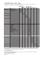
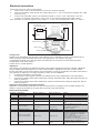
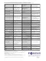
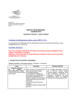
Pressure and differential
pressure transmitter PT60
Electronic transmitter with a wide range of process
connections. Stainless steel housing with hygienic design.
PT60
a series of pressure transmitters with great flexibility.
Modulary built. A wide range of process connections and electronics can be choosen.
Hygienic design
stainless steel, no dirt collecting gaps
or pockets . Easy to clean and
minimal risk for corrosion.
EMC rugged construction. Housing
in stainless steel with excellent
shielding.
Constructed for washing
with high pressure cleaners.
IP67 housing.
Different electronics.
- Analogue, 4-20 mA
- HART, 4-20 mA
- Profibus PA
- FOUNDATION fieldbus (pending)
Can be delivered with 19 different directly connected process
connections for both pressure and
differential pressure.
150°C media temperature (short
time 200°C).
Accuracy of 0,1 %.
Transmitter types, order codes:
The transmitters order codes for different configurations can be found from the table below. All
combinations are not possible, see next page for exceptions.
PT60 x x x - x x x x x
D e s cription
Ele ctronics
D e s ign
D iaphragm
Conne ction
Span min.-max.
M e as . type
Filling liquid
Suffix
Analogue 4-20 mA
A
HART 4-20 mA
H
Profibus PA
PA
Foundation Fie ldbus (7)
FF
D e s ign Figure 1 Figure 2 Figure 3 Figure 4
Intrins ic s afe (1)
E
Ligthning prote cte d
L
Stainle s s s te e l 1.44621 (5)
3
Has te lloy C-276 (5)
4
Tantalum (5)
5
R 1/2" e xte rnal.
1
N PT 1/2" e xte rnal.
2
R 1 1/2" e xte rnal
3
Flange 80 mm/3"
4
Flange 50 mm/2"
5
R e movable during ope r.
6
D IN 11851/40 mm
7
SM S R d60-6
8
Clamp 38
9
Clamp 51
A
R JT 1 1/2"
C
D R D Conne ction
D
D IN 11851/50 mm
E
Hygie nic front conne ction
P
Varive nt 2"
V
D iffe re ntial pre s s ure (3)
G
D iff. pre s s ure with flange (3)
H
D P with capillary tube (3)
T
Trans mitte r with capillary
tube (3)
N
0,24-7 kPa
1
1,2-35 kPa
2
6,7-200 kPa
4
0,067-2 M Pa
6
0,14-4 M Pa (4)
7
0,27-8 M Pa
7
0,5-15 M Pa
8
Atmos phe ric pre s s ure
0
Abs olute pre s s ure
2
Silicon oil (2)
Oil fre e de s ign (6)
Empty
H
Ordering example: Threaded transmitter with external R1/2” connection, pressure range 0-90 kPa for
atmospheric pressure and HART electronics (silicon oil filling and Hastelloy diaphragm) will have order
code: PT60H-4140 with calibrated measuring range 0-90 kPa.
(1) Not with analogue electronics.
(2) FDA approved silicon oil.
(3) Type G with connection 1/4” NPT thread. Type H with flange 80 mm/3” one side. Type T see description on next page.
(4) Only for connection 8 (SMS Rd60-6).
(5) See next page for permitted combinations.
(6) Oil free and filled with halocarbon.
(7) Pending.
Transmitter types, description:
Threaded transmitter R 1/2" and
NPT 1/2”. (1 and 2)
The threaded transmitter with
connection to R 1/2” thread is
intended for clean media. At a
media temperature higher than
90ºC, a cooling pipe is used to
prevent too high temperature at
the sensor.
The threaded connection is
normaly sufficient to keep the
transmitter in place. At specific
conditions or wall installation the
transmitter can be supported and
reinforced with an installation
kit.
(Exceptions: Normally not available
with tantalum diaphragm.)
the limits depends on flange type.)
Hygienic clamp connected
transmitter.
Clamp38, Clamp51, hygienic front
connection and Varivent. (9, A, P
and V)
A clamp connected transmitter is
used when special hygiene
requirements are needed, such as
those in the food and pharmaceutical industry. The design meets
ISO 2852 and the transmitter is easy
to install and remove.
If clamp 38 connection is not
available, the optional connector
piece, clamping ring and gasket
ring may be used. Connection
details for clamp 51, hygienic front
Threaded transmitter with
connection and Varivent is available
extended diaphragm, R1 ½ ”.
upon request but not available from
(3)
stock.
This transmitter connection with (Exceptions: Normaly not available
a connection to a 1½” thread is
with tantalum or stainless steel
intended for fibre-rich and viscous diaphragm.
media. The extended front
The highest pressure range for
diaphragm is in connection with
clamp 38/51 and Varivent is 2 MPa.
the media without any pocket
Note that the limits depends on
inside the tank or pipe.
clamping ring type.)
An optional adapter is available
for connection to a 2" thread and
Hygienic screw connected
an optional welding sleeve for
transmitter.
R1½”. There are no additional
DIN11851/40 mm, SMS Rd60-6,
requirements on the installation. DIN11851/50 mm. (7, 8, C, E)
The transmitter may also be
A screw connected transmitter
connected inside a threaded
giving a hygienic connection, for
R1½” cylinder, such as a pipe
example, used in the Dairy
sleeve or shut-off valve.
industry. The exposed diaphragm
(Exceptions:
has direct contact with the media
Not available with tantalum
which make it possible for the
diaphragm and pressure range 14
transmitter to measure even
and 35 kPa.
viscouse liquid media, without
The highest pressure range for this becoming silted up.
connection type is 4 MPa).
The transmitter is installed in
accordance with the Rd 60-6
Flange connected transmitter.
connection of SMS 1146, DIN 405
Flange 80 mm/3”, Flange 50
and DIN 11851. The transmitter is
mm/2” and DRD flange. (4, 5
screwed to the connector.
and D)
(Exceptions: Normaly not available
A flange connected transmitter is with tantalum or stainless steel
intended for level measurement in diaphragm.
open tanks with liquid media,
The highest pressure range for
even with fibre rich and/or
DIN11851/40 is 2 MPa. The highest
viscous media. The risk of
pressure range for SMS Rd60-6 is 8
blockage is eliminated by the
MPa.)
large area of the exposed
diaphragm.
Transmitter removable during
The transmitter is clamped
operation. (6)
between standard flange rings.
This transmitter type is intended
The transmitter fits slip-on
for liquid media, even with
flanges of ANSI or DIN type. For
viscous or fibre-rich media. The
transmitters with flange
extended diaphragm is in
connection, the type of flange has connection with the media
to be stated at the time of order.
without any pocket inside the
(see Accessories).
tank or pipe.
PT60 with flange 50 mm/2" and six
The transmitter can be exchanged
holes, for use with MWP10 is
during operation and comprises
supplied upon request.
three parts; the transmitter, a ball
(Exceptions: Not available with
valve and a welded casing/
tantalum diaphragm combined
compression flange. This
with pressure range 14 and 35 kPa. compression flange is designed to
The highest pressure range for this
fit an ANSI or DIN 80 mm/3”
connection type is 4 MPa. Note that
flange and may be installed to
measure levels according to the
hydrostatic principle.
(Exceptions: Normaly not available
with tantalum diaphragm.
The highest pressure range for this
transmitter type is 2 MPa.)
Differential pressure
transmitter. (G, H and T)
Differential pressure transmitters
is used to meausre the difference
between two pressures. The
transmitter types G and H can
withstand high static pressures,
both one- and doublesided, (up to
15 MPa). The transmitter type G
has threaded connection and type
H has one side threaded and the
other side with flange 80 mm.
They are used for level
measurements in pressure vessels
and flow measurements of gases,
liguids and vapour. Other
application areas are differential
pressure measurements across
filters or heat exchangers, and
pressure measurements with
narrow measurement ranges
where there is a danger of high
one-sided pressure overload.
The differential pressure
transmitter type T can be
delivered with two process
connections 3-9, A, C, D, E och V.
One side is directly connected to
the transmitter and the other side
with a capillary tube (normal
lenght of the capilary tube is 2000
mm, other length upon request).
(Execeptions: Type G: Threaded
connection is not available with
tantalum or stainless steel
diaphragm. Flange connection is
not available with Tantalum
diaphragm.The highest pressure
range is 0,8 MPa.
Type T: Highest static pressure is
the same as the overload for the
pressure range. Same exceptions as
for the choosen process connection.)
Transmitter with capillary
tube. (N)
This transmitter type is designed
with the connection (with the
measuring diaphragm) separated
from the transmitter housing.
The media pressure is transferred
via a capillary tube (normal
lenght of the capi lary tube is 1000
mm, other length upon request) to
the sensor located in the
transmitter housing. This type
can be delivered with process
connections 3-9, A, C, D, E and V.
The transmitter type is designed
for applications with high
vibration levels or high ambient
temperatures.
Withstands extremly high media
temperartures (max 275 degrees C).
(Exceptions: Same exceptions as for
the choosen process connection.)
Function:
Transmitter for Pressure and
Level
The PT60 uses a piezo-resistive
pressure sensor which is
connected to the pressure of the
medium via a capillary tube and
a diaphragm. Media pressure
applied to the diaphragm is
transferred via silicon oil to the
pressure sensor. The oil
completely fills the cavity in the
sensor, the capillary tube and the
cavity above the diaphragm. This
means that the diaphragm
movement is very small at
pressure changes. The capillary
To transmitter
electronics
Electronics
Reference tube
Sensor
Slit for
atmospheric
pressure
Capilary tube
Diaphragm
The pressure of the medium is
transferred to the sensor via
silicon oil relaying diaphragm
movements
tube protects the pressure sensor
from transient pressure surges.
To ensure that the sensor has the
correct reference pressure, the rear
side is connected to ambient
atmospheric pressure, via a tube,
designed in order that air passes
“cold surfaces” closest to the
pressure connection of the
transmitter. Any humidity in the
air will condense on these
surfaces. The condensate flows
out and the remaining air in the
tube stays dry. Additionally, the
reference pressure connection is
designed to prevent flushing
water from entering.
PT60 has microcomputer-based
electronics, which communicate
with the outside world with 4 to
20 mA signal as well as HART
communication (PT60H). The
electronics measure and converts
the output signal from the pressure
dependent sensor bridge to digital
values. Furthermore, the total
resistance of the sensor bridge is
measured and these values are
converted to digital temperature
values.
The electronics perform
compensation for temperature
drift of the sensor by means of
compensation values entered at
the factory calibration and at the
same time the temperature
measurement is also calibrated.
Compensation for the nonlinearity in the sensor is done in
the same manner.
Different kinds of transfer
functions, such as linear, square
root, curves..., can be selected. The
electronics perform the calculation
for the selected transfer function
and then the digital value is
converted to analogue for the 4 to
20 mA current loop. The digital
value can also be read via HART
(PT60H) communication in optional
engineering units, percentage or
current.
PT60 can be configured/calibrated
to a certain extent by means of keys
and switches in the connection
space and fully by means of a hand
terminal or a PC via HART (PT60H)
communication.
Transmitter for Differential
Pressure
The transmitter has a central piezoresistive sensor connected to the
membrane chambers via two
capillary tubes.
Each of the two process media
pressures act on a separating
membrane that have a small spring
To transmitter
electronics
Electronics
Sensor
Measuringdiaphragm
Overload
diaphragm
The pressure is transferred
from the media to the sensor
element via the separating
diaphragms by means of silicon
oil.
constant. An overload membrane
with adapted spring constant is
located between the two separating
membranes. The membrane
chambers and the sensor are filled
with silicon oil. The pressure on
both sides of the overload
membrane is transferred to the
sensor by means of the silicon oil.
At a pressure difference between the
two separating membranes within
the measuring range of the
transmitter, all three membranes
will move freely. At overload
exceeding the measuring range
one of the separating membranes
will however lay against the
profiled surface while the
overload membrane still can move
freely. The differential pressure
across the sensor can in that way
not increase further even if the
differential pressure across the
separating membranes increases.
This protects the sensor against
overload and transient pressure
surges.
The electronics perform
compensation for temperature
drift of the sensor by means of
compensation values entered at
factory calibration, and at the
same time the temperature
measurement is also calibrated.
Compensation for the nonlinearity in the sensor is done in
the same manner.
Different kinds of transfer
functions, such as linear, square
root, curves..., can be selected.
The electronics perform the
calculation for the selected transfer
function and converts the digital
value to an analogue signal for the
current loop 4 to 20 mA. The digital
value can also be read via HART
(PT60H) communication in optional
engineering quantity, percentage
or current.
PT60 can be configured/calibrated
to a certain part by means of keys
and switches in the connection
space and fully by means of a hand
terminal or a PC via HART (PT60H)
communication.
PI100
PI100 is a software tool on CDROM for Windows95/98/2000/XP
and Windows NT for configuration,
calibration and documentation.
PI100 contains a database with
available transmitter types. The
program can configure
transmitter specific values and
perform maintenance, output
signal and factory calibration.
Furthermore, PI100 performs
copying of current configuration,
backup on to hard disc,
transmitting/receiving via standard
HART communication and a selftest with alarm functions.
PI100 contains online presentation
of help functions, data sheets and
user manual.
Hand terminal
For parameter settings a hand
terminal of HART type can be
used, see more detailed
description in PI100 User Manual.
Approvals
PT60 with connections 7, 8, 9, A, D,
E and V are approved for 3A.
PT60 is approved by DNV and
explosionproof, EEx ia IIC T4, by
NEMKO (according to the EU
directive ATEX) .
PT60 are CE approved according to
the EU directives for pressure
equipment, PED, and EMC.
To concider
To obtain longtime and faultless
operation of PT60 there are some
important factors to consider when
choosing transmitter type and at
installation.
Al types
Pressure transmitters with
piezoresistive sensors is designed
to withstand a specific overload
(see data). If the pressure on the
diaphragm exceeds this limits,
irrespective if it is for a long or
short time, the sensor will be
broken permanently.
Consider if such pressures will
arise in the plant and choose the
right type of sensor. If there is for
example valves closing fast in
connection to the transmitter
high pressure surges can arise
Can there for example be steam
surges?
The measuring diaphragm is the
most exposed and easily affected
part of the transmitter.
If the media is corrosive consider
choosing the right diaphragm
material. If there is any
uncertainty please contact us for
advise.
If existing diaphragm types is not
sufficient it is possible to deliver
transmitters with diaphragm
coatings, for example teflon,
epoxy, rubber. Please contact us
for information.
Even though a diaphragm
material is sufficient for a
corrosive media it will be slightly
affected. This imply that the
measurement will be slightly
changed over time (especially the
zero point). This can be corrected
by performing a maintenance
calibration or a recalibration.
The transmitters electronic- and
electric connection housing is
approved for IP66. Use round
signal/supply cable and tighten
the cable feed through firmly.
Make sure that the electronic
housing cover is tight.
If the transmitter is installed in a
dirty environment, make sure
that the reference slit (see picture
page before) always is open for the
atmospheric pressure.
In plants with high vibration
levels it is important to secure
that the transmitters
performance is sufficient. The
most certain is to measure the
vibrations amplitude resp.
acceleration.
The transmitters are designed
and tested for:
3-25 Hz, amplitude 1,6 mm
25-60 Hz, amplitude 0,21 mm
60-100 Hz, accel. 19,6 m/s2
(Standards: IEC770 and DNV
Certification note 2.4 location
class B.)
If vibration levels exceeds this
consider using the transmitter
type N (see Transmitter Types
Description).
Transmitter removable during
operation. (connection 6)
There are certain considerations
that must be considered for this
transmitter type. The diaphragm
is more exposed on this type
because the transmitter is pushed
in/out of the valve.
Assure that the valve is not
plugged or closed when the
transmitter is pushed in. If soo
the sensor might be permanently
damaged.
This transmitter type has a small
diaphragm and it is sensitive to
damaged or corroded diaphragms.
A maintenance calibration or
recalibration might be required
periodically.
Warning:
The transmitter cannot be replaced
at high pressure due to the large
force required to push the
transmitter back into the valve
housing. The area affected by the
pressure is 7.5 cm2.
The transmitter must not be
pushed in when the ball valve is
closed.
The transmitter must be fully
extended before the ball valve is
operated.
Accessories:
De s cription:
Trans mitte r type :
Code :
De s cription:
Trans mitte r type :
Code :
Ins tallation kit
1, 2
P110301
Gas ke t ring clamp 38
9
K380002
We lding s le e ve
3
P130201
Clamp ring 51
A
K380003
Adapte r 2" to R 11/2"
3
P130301
Conne ction pie ce clamp 51
A
K380004
Flange 80 mm PN40 DIN2656 SS
4
P130401
Gas ke t ring clamp 51
A
K380005
Flange 80 mm PN10 DIN2656 SS
4
P130402
We lding s tud 60 mm
6
P122901
Flange 50 mm PN40 316L/1.4404
5
P103602
Compre s s ion flange DN80
6
P123101
Flange 50 mm PN10 316L/1.4404
5
P103601
Ball valve PN63, DN32
6
P123001
Flange 50 mm PN6 316L/1.4404
5
P103603
Dis play
All type s
P130501
Flange 50 mm "s lip on" 150 lb
5
P109801
Configuration program for PC (Win.)
PT60H
PI2000
Flange 50 mm "s lip on" 300 lb
5
P109802
Hygie nic with e xte nde d diaphragm 38
9
P112201
Flange 50 mm "s lip on" 600 lb
5
P109803
Ele ctropolis hing of me dia touche d parts
4-9, A, C, D, E, V 102511
Clamp ring 38
9
K380000
M ate rialce rtificat (3.1.B ce rtificat)
All type s
102512
Conne ction pie ce clamp 38
9
K380001
Calibration ce rtificat
All type s
102510
Electrical connection
Follow this instruction (see pictures below):
1.
Remove the cover of the transmitter to access the terminal chamber.
2.
Wire the transmitter cable through the cable bushing Pg 11. Use round cable and tighten the cable
bushing firmly.
3.
Connect the transmitter cable to the terminals marked S+ and S–. Max. cable area is 2,5 mm2.
If there is a separate shield cable, connect this to the terminal marked with shield symbol.
(The transmitter is protected against wrong polarity. If + and- are exchanged there will be no signal.)
PT60, connection and setting
Connection of
handterminal/modem
Test terminal
Ry, min 250 ohm
11-55 V DC
Shield terminal
Minus button
Switch
Plus button
Settings PT60
Settings of the transmitters span and zero is done directly on the transmitter by means of push buttons and a
switch. First push of button activates the function. See figure above and tabel on next page.
In all positions except B and G the new values are saved after 30 seconds and normal measuring starts,
independently of the switch position.
Position B is for normal operation.
Adjustment
Upon delivery, the transmitter is adjusted according to the specific requirements from the customer. Adjustment
may be needed after being repaired or for check of the transmitter. Adjustment of the time constant, transfer
function and locking current is done directly on the transmitter by means of push buttons and switch. Note that it is
only necessary to adjust zero, according to position 4 below, at new installations.
1.
Connect the transmitter to power supply.
2.
To measure the output signal, connect a low resistance (R<6 ohm) amperemeter to the test terminal.
3.
Connect the pressure which shall constitute the maximum measured value. Adjust the higher limit with the
switch in position D.
4.
Connect the pressure which shall constitute the minimum measured value. Adjust the lower limit with the
switch in position C.
Adjustment via the HART communication (PT60H)
Adjustment of all transmitter parameters can also be done with the PC program PI100 via HART modem. The
modem is connected according to the figure above. See also PT60 User Manual.
Switch positions PT60A
P osition
Function
Minus button (-)
P lus button (+)
N ote
A
S elftest 30 seconds/
Factory reset
Restart
Restart
B oth si multaneously for at least
10 s. resetts factory adjustments.
B
Normal measuri ng
None
None
C
Zero
D ecreases mA
Increases mA
B oth si multaneously gi ves 4 mA
D
Span
D ecreases mA
Increases mA
B oth si multaneously gi ves 20
mA
E
Ti me constant
D ecreases ti me
(0,1-10 s)
Increases ti me
(0,1-10 s)
B oth si multaneously gi ves 0,1 s.
The output si gnal shows the ti me
constant accordi ng to
10mA+1mA/1s
F
Transfer functi on
Li near
S quare root
G
Locki ng of current/
C urrent cali brati on
S ets 4 mA
S ets 20 mA
When depressi ng plus for 5 s the
functi on changes to cali brati on of
20 mA (can then be adjusted
wi th +/- buttons).
When depressi ng mi nus for 5 s
the functi on changes to
cali brati on of 4 mA (can then be
adjusted wi th +/- buttons).
H
Autozero
None
None
B oth si multaneously puts the
appli ed pressure as zero out.
Switch positions PT60H
P osition Function
Minus button (-)
P lus button (+)
N ote
A
S elftest 30 seconds Restart
Restart
B
Normal measuri ng
None
None
C
Zero
D ecreases mA
Increases mA
B oth si multaneously gi ves
4 mA
D
Span
D ecreases mA
Increases mA
B oth si multaneously gi ves
20 mA
Ti me constant
D ecreases ti me
(0,1-10 s)
Increases ti me
(0,1-10 s)
B oth si multaneously gi ves
0,1 s. The output si gnal
shows the ti me constant
accordi ng to
10mA +1mA /1s
F
Transfer functi on
Li near
S quare root
G
Locki ng of current
S ets 4 mA
S ets 20 mA
H
A utozero
A cti vate
None
E
B oth si multaneously puts
the appli ed pressure as
zero out.
One button press gives 0,1 mA in position C and D. A continuously pressed button has a rate of change of 0,1 mA/
0,5 s. After 5 s the rate of change is increased to 1 mA/1 s.
In position E one button press gives 0,1 s between 0,1-3 s and 1 s between 3-10 s. The output signal shows the
time constant according to 10 mA+1 mA/1 s.
Maintenance and repair
To obtain longtime and faultless
operation of PT60 some
maintenance must be performed
periodically. The time between
maintenance depends on different
conditions, for example transmitter
type, type of media, surrounding
environment (For example,
corrosive media or particles in the
media migth affect the diaphragm
and require short time between
maintenance.) Generally
maintenance should be carried out
at least once a year.
PT60PA and PT60FF
PT60PA and PT60FF have no
adjustments direct on the
transmitter. The adjustments are
only accessible via the communication.
Generic software tools for PA and
FF can be used.
See description in the User´s
Manual for PT60PA/FF (released
2001).
Outline:
(mm)
R11/2” ext,
PT60A is adjusted according to
instructions on previous page.
PT60H/PA/FF can be adjusted by
performing a maintenance
calibration via HART
communication and the PC
program PI100. (Alternatively an
adjustment is done according to
instructions on previous page.)
Selected spare parts to PT60
can be delivered, please contact us
for information.
Repair is handled as an exchange
system with fixed prices.
Flange 50/80
Removable
92,5
170/172
181
267
diam. 70
Transmitter size
R 11/2”
17/19
diam. 72/90
diam. 96/127
diam. 40
R1/2”ext.
NPT 1/2” ext.
SMS Rd60-6
152
diam. 60
Clamp 38/51
DP (type G)
166
171
178,5
1/4” NPT
M 10
R 1/2”
41,3
41,5
35
diam. 50,5/64
diam. 55
54
Technical data PT60H/PA (differing data for PT60A in brackets)
Electronic pressure
transmitter with
microcomputer based
electronics.
Directly connected
transmitter with no
pressure intermedium.
Piezo- resistive sensor
with capillary tube.
Adjustable from - 100%
to 100% of the max,
pressure range value.
Type :
Function:
Ope rating range :
Exte rnal s e rie s
re s is tance :
R kohm =
(Supply voltage - 9)/20.
For HART communication min. 250 ohm.
Se rie s re s is tance
de pe ndant:
Less than +/- 0,1%
Supply voltage
de pe ndant:
Less than 0,1 %
M e as uring s pan:
Adjustable from the max.
pressure range to 1/30 of
this.
Te mpe rature tole rance :
Ze ro point s uppre s s ion:
Adjustable from - 100%
to 100% of the max,
pressure range value.
Working pre s s ure
de pe nde nce : *1
Max 15 MPa, static
pressure. Flange 4 MPa.
Long time s tability:
Max 100 kPa
Vibration tole rance :
Working pre s s ure :
Ove rload:*3
*1
7 kPa
35 kPa: Max 250 kPa
4/8/10/15 MPa: Max 30 MPa
M ate rial:
Stainless steel/Hastelloy
Diaphragm: /Tantalum *6 (special
coatings upon request).
Related parts: Stainless steel 1.4435
Housing: Stainless steel 1.4306
Less than +/- 0,1%
(0,25%) of max. span.
(For the range - 10 to +70
degrees C.)
Max 0,06% per MPa at
max measuring range (200
kPa och 1 MPa)
Max 0,2% per MPa at
max measuring range (35
kPa).
Less than 0,08 % per
year.
Perpendicular to diaphragm: Max +0,3 kPa/G
200 kPa: Max 500 kPa
2 MPa: Max 3 MPa
:* 4
Parallel to diaphragm: Max +0,02 kPa/G
Meets tests according to.
IEC770 and DN V class B
Less than +/- 0,1 % of
measuring range.
Less than +/- 0,1 % of
adj. span (includes
linearity, hysteresis and
repeatability). *2
Direct on process
connection.
Vibration te s t:
R e pe atability:
Accuracy:
Ins tallation:
Ele ctrical conne ction:
Internal terminal block.
Max wire area: 2,5 mm2
Ambie nt te mpe rature :
- 20º to +80º C
Time cons tant:
Interchangeable between
0,1- 10 s. As delivered
0,1 s.
M e dia te mpe rature :
1 5 0º C
Prote ction clas s :
IP67
Output s ignal:
4- 20 mA, two wire
connection, the signal
proportional to pressure.
Max. current at overload
22,5 mA. HART ,
Profibus PA or FF
communication.
Ele ctrical s afe ty:
Meets the EN 60204- 1
Supply voltage :
11- 55 V DC
Ele ctrical inte rfe re nce :
Meets the
EN 61326- 1- 2- 3
Pre s s ure s afe ty:
According to EU directive
PED (97/23/EG)
Intrins ic s afe ty (ATEX):
EExia IIC T4 (N emko)
Filling
We ight:
*5
AK 100 silicon oil FDA
approved for use with
food.
Between 700- 1500 g
dependent on type
Cable entry:
Pg11 for round cable 5- 12
mm.
*1 Only for differential pressure transmitter.
*2 Applies for turn down 1:1 to 1:15. For turn down 1:16 to 1:30 accuracy increases
0,1% to 0,25%. Base accuracy 0,05 % on request.
*3 Applies for the sensor. For different types of processconnections there are
mechanical limits.
*4 Some data diverge for Profibus PA.
*5 Short time 200 degrees C. Some types upon request 275 degrees C.
*6 Diaphragm surface smoothness (Ra): Standard 0,75 um, on request 0,15 um.
Specifications subject to change without notice. Printed in Sweden. ©2008 Pondus Instruments AB.
PT60_0805_EN
2008-05-08