1
L4 User Manual
Version 1.14
Alan Au, Gernot Heiser
School of Computer Science and Engineering
The University of New South Wales
Sydney 2052, Australia
alanau,gernot @cse.unsw.edu.au
March 15, 1999
Version 1.5 is identical to UNSW-CSE-TR-9801 of June 1998
School of Computer Science and Engineering
The University of New South Wales
Sydney 2052, Australia
Abstract
This document is a user manual for the L4 -kernel. It gives an introduction to the main concepts and
features of L4, and explains their use by a number of examples. The manual is generally platform
independent, however, examples are based on the C interface for L4/MIPS. Actual system call C
bindings and data formats differ slightly on other platforms.
This document supplements, rather than replaces, the L4 Reference Manual, and anyone intending to
write an applications on top of L4 should obtain the L4 Reference Manual for their particular platform.
Permission to make digital/hard copy of part or all of this work for personal or classroom use is granted without
fee provided that copies are not made or distributed for profit or commercial advantage, the copyright notice,
the title of the publication and its date appear, and notice is given that copying is by permission of the authors.
To copy otherwise, to republish, to post on servers, or to redistribute to lists requires prior specific permission
and/or a fee.
Copyright c 1998 by Gernot Heiser, The University of New South Wales.
Preface
This manual grew out of lecture notes for a course on Advanced Operating Systems given by Gernot Heiser at UNSW in July–November 1997. In that course students had to build a small operating
system on top of L4/MIPS which had previously been developed at UNSW by Kevin Elphinstone
with lots of help from Jochen Liedtke. We would like to thank the 44 students of that course (one of
whom was Alan Au) for their interest and patience, as well as for their questions which prompted the
lecturer to write and provide further documentation. We would further like to thank Jochen Liedtke
for providing the L4 specification and the original reference manual, Kevin Elphinstone for the MIPS
implementation as well as for explaining L4’s idiosyncrasies, the OS group at the Technical University of Dresden under Herrman Härtig for example code, C bindings and manual pages, and Jerry
Vochteloo and many others for their contributions.
It is expected that this manual will continue to grow as more people are learning to use L4,
and consequently discover shortcomings of the documentation. We welcome comments, corrections and enhancements and will try to incorporate them quickly into the manual. The latest version of this manual (as well as of the L4/MIPS Reference Manual [EHL97]) are available from
http://www.cse.unsw.edu.au/˜disy.
Contents
1 Introduction
1
1.1
L4 design philosophy . . . . . . . . . . . . . . . . . . . . . . . . . . . . . . . . . .
1
1.2
L4 abstractions and mechanisms . . . . . . . . . . . . . . . . . . . . . . . . . . . .
2
1.2.1
Address spaces . . . . . . . . . . . . . . . . . . . . . . . . . . . . . . . . .
2
1.2.2
Threads . . . . . . . . . . . . . . . . . . . . . . . . . . . . . . . . . . . . .
3
1.2.3
IPC . . . . . . . . . . . . . . . . . . . . . . . . . . . . . . . . . . . . . . .
3
1.2.4
Clans & chiefs . . . . . . . . . . . . . . . . . . . . . . . . . . . . . . . . .
3
1.2.5
UIDs . . . . . . . . . . . . . . . . . . . . . . . . . . . . . . . . . . . . . .
4
1.3
Resource allocation . . . . . . . . . . . . . . . . . . . . . . . . . . . . . . . . . . .
4
1.4
Organisation of this manual . . . . . . . . . . . . . . . . . . . . . . . . . . . . . . .
5
2 L4 IPC
6
2.1
IPC Overview . . . . . . . . . . . . . . . . . . . . . . . . . . . . . . . . . . . . . .
6
2.2
L4 IPC Messages . . . . . . . . . . . . . . . . . . . . . . . . . . . . . . . . . . . .
6
2.2.1
Message Data Types . . . . . . . . . . . . . . . . . . . . . . . . . . . . . .
6
2.2.2
Messages . . . . . . . . . . . . . . . . . . . . . . . . . . . . . . . . . . . .
9
2.2.3
Sending/Receiving IPC Messages . . . . . . . . . . . . . . . . . . . . . . .
12
Clans and Chiefs . . . . . . . . . . . . . . . . . . . . . . . . . . . . . . . . . . . .
24
2.3.1
Concepts . . . . . . . . . . . . . . . . . . . . . . . . . . . . . . . . . . . .
24
2.3.2
Usage and Cost . . . . . . . . . . . . . . . . . . . . . . . . . . . . . . . . .
25
2.3
3 Other L4 System Calls
29
3.1
Task Creation and Deletion . . . . . . . . . . . . . . . . . . . . . . . . . . . . . . .
29
3.2
Thread Related System Calls . . . . . . . . . . . . . . . . . . . . . . . . . . . . . .
30
vii
3.2.1
Thread Manipulation . . . . . . . . . . . . . . . . . . . . . . . . . . . . . .
30
3.2.2
Release CPU . . . . . . . . . . . . . . . . . . . . . . . . . . . . . . . . . .
30
3.2.3
Thread Scheduling . . . . . . . . . . . . . . . . . . . . . . . . . . . . . . .
31
3.2.4
Obtaining Thread Identifiers . . . . . . . . . . . . . . . . . . . . . . . . . .
33
3.3
Revoking Mappings . . . . . . . . . . . . . . . . . . . . . . . . . . . . . . . . . . .
34
3.4
An Example . . . . . . . . . . . . . . . . . . . . . . . . . . . . . . . . . . . . . . .
35
4 Using L4
38
4.1
Bootstrap . . . . . . . . . . . . . . . . . . . . . . . . . . . . . . . . . . . . . . . .
38
4.2
Resource Allocation . . . . . . . . . . . . . . . . . . . . . . . . . . . . . . . . . . .
38
4.3
- The Root Pager . . . . . . . . . . . . . . . . . . . . . . . . . . . . . . . . . . .
39
4.3.1
Kernel Information Page . . . . . . . . . . . . . . . . . . . . . . . . . . . .
40
4.3.2
DIT . . . . . . . . . . . . . . . . . . . . . . . . . . . . . . . . . . . . . . .
40
4.3.3
RPC Protocol . . . . . . . . . . . . . . . . . . . . . . . . . . . . . . . .
43
4.4
Page Fault Handling . . . . . . . . . . . . . . . . . . . . . . . . . . . . . . . . . . .
47
4.5
Exception And Interrupt Handling . . . . . . . . . . . . . . . . . . . . . . . . . . .
49
4.5.1
Exception Handling . . . . . . . . . . . . . . . . . . . . . . . . . . . . . .
49
4.5.2
Interrupt Handling . . . . . . . . . . . . . . . . . . . . . . . . . . . . . . .
49
OS On L4 . . . . . . . . . . . . . . . . . . . . . . . . . . . . . . . . . . . . . . . .
50
4.6.1
OS Structure . . . . . . . . . . . . . . . . . . . . . . . . . . . . . . . . . .
50
4.6.2
Some Conventions . . . . . . . . . . . . . . . . . . . . . . . . . . . . . . .
51
4.6
Chapter 1
Introduction
L4 is an operating system microkernel ( -kernel). That is, L4 by itself is not an operating system
(OS), but rather constitutes a minimal base on which a variety of complete operating systems can be
built. In this chapter we will summarise the main ideas behind L4.
The basic idea of a -kernel goes back to Brinch Hansen’s Nucleus [BH70] and Hydra [WCC 74]
and has been popularised by Mach [RTY 88]. The argument goes that by reducing the size of the
kernel, the part of the operating system (OS) executing in privileged mode, it becomes possible to
build a system which is more secure and reliable (because the trusted computing base is smaller) and
easy to extend. A further advantage is that a -kernel-based system can easily implement a number
of different APIs (also called OS personalities) without having to emulate one within the other.
There was also hope of improved efficiency, as operating systems tend to grow as new features are
added, resulting in an increase of the number of layers of software that need to be traversed when
asking for service. (An example is the addition of the VFS layer in UNIX for supporting NFS.) A
microkernel based system, in contrast, would grow horizontally rather than vertically: Adding new
services means adding additional servers, without lengthening the critical path of the most frequently
used operations.
However, performance of these first-generation microkernels proved disappointing, with applications
generally experiencing a significant slowdown compared to a traditional (“monolithic”) operating system [CB93]. Liedtke, however, has shown [Lie93, Lie95, Lie96] that these performance problems are
not inherent in the microkernel concept and can be overcome by good design and implementation. L4
is the constructive proof of this theorem, as has been clearly demonstrated by Härtig et al. [HHL 97].
1.1 L4 design philosophy
The most fundamental task of an operating system is to provide secure sharing of resources, in essence
this is the only reason why there needs to be an operating system. A -kernel is to be as small as
possible. Hence, the main design criterion of the -kernel is minimality with respect to security: A
service (feature) is to be included in the -kernel if and only if it impossible to provide that service
outside the kernel without loss of security. The idea is that once we make things small (and do it well),
performance will look after itself.
1
A strict application of this rule has some surprising consequences. For example device drivers: Some
device drivers access physical memory (e.g. DMA) and can therefore break security. They need to
be trusted. This, however, does not mean that they need to be in the kernel. If they need not execute
privileged instructions, and if the kernel can provide sufficient protection to run them at user level,
then this is what should be done, and, consequently, this is what L4 does.
1.2 L4 abstractions and mechanisms
Based on such reasoning Liedtke concludes that the -kernel needs to provide:
address spaces because they are the basis of protection,
threads because there needs to be an abstraction of program execution,
inter-process communication (IPC) as there needs to be a way to transfer data between address
spaces,
unique identifiers (UIDs) for context-free addressing in IPC operations.
We will look at these in turn.
1.2.1 Address spaces
An address-space contains all the data (other than hardware registers) which are directly accessible by
a thread. An address space is a set of mappings from virtual to physical memory (which is partial in
the sense that many mappings are undefined, making the corresponding virtual memory inaccessible).
Address spaces in L4 can be recursively constructed: A thread can map parts of its address space into
another thread’s address space (provided the receiver cooperates) and thereby share the data mapped
by that region of the address space. Mappings can be revoked at any time, so the mapper retains full
control.
Alternatively, virtual address space can be granted to a different address space. In this case the granter
relinquishes all control over the data mapped by that part of the address space and no longer has a
valid mapping for that address space region. The granter cannot revoke a grant. The grantee, in
contrast, inherits full control over the granted address space (unless the grant was read-only, in which
case write access is lost.) Note that while a grant is irreversible, the granter has, in general, received
the address space (directly or indirectly) via mapping, and an address space at the beginning of the
mapping chain can still revoke the mapping.
Mapping and granting are implemented as operations on page tables, without copying any actual data.
Mapping and granting is achieved as a side effect of IPC operations and specified by the means of flex
pages. This is not accidental: For security reasons mapping requires an agreement between sender
and receiver, and thus requires IPC anyway. Details will be explained in Section 2.2.1.
The concept of a task is essentially equivalent to that of an address space. In L4, a task is the set
of threads sharing an address space. Creating a new task creates an address space with one running
thread.
Strictly speaking the number of tasks is a constant. There are two kinds of tasks: active and inactive
ones. When we say that a task is created we mean that an inactive task is activated. Inactive tasks are
essentially capabilities (task creation rights). This is important, as a thread can only create a task if it
already owns the task ID to use. Inactive tasks can be donated to other tasks.
There is a hierarchy of tasks, with parents having some limited control over their children. The main
purpose of this is to be able to control (IPC-based) information flow between address spaces. It has
nothing to do with process hierarchies a particular L4-based personality OS may implement. Such a
hierarchy is under full control of the particular OS personality.
1.2.2 Threads
A thread is the basic execution abstraction. A thread has an address space (shared with the other
threads belonging to the same task), a UID, a register set (including an instruction pointer and a stack
pointer), a page fault handler (pager), and an exception handler. IPC operations are addressed to
threads (via their UIDs). Threads are extremely light-weight and cheap to create, destroy, start and
stop. The lightweight thread concept, together with very fast IPC, is the key to the efficiency of L4
and OS personalities built on top.
1.2.3 IPC
Message-passing IPC is the heart of L4. The -kernel provides a total of seven system calls (IPC
being one of them), which provide some very rudimentary OS functionality. Everything else must be
built on top, implemented by server threads, which communicate with their clients via IPC.
IPC is used to pass data by value (i.e., the -kernel copies the data between two address spaces) or
by reference (using mapping or granting). IPC is also used for synchronisation (as it is blocking, so
each successful IPC operation results in a rendez-vouz), wakeup-calls (as timeouts can be specified),
pager invocation (the -kernel converts a page fault into an IPC to a user-level pager), exception
handling (the -kernel converts an exception fault into an IPC to a user-level exception handler), and
interrupt handling (the -kernel converts an interrupt fault into an IPC to a user-level interrupt-handler
from a pseudo-thread). Device control is registered via IPC (although actual device access is memory
mapped).
1.2.4 Clans & chiefs
Clans and chiefs are L4’s basic mechanism enabling the implementation of arbitrary security policies [Lie92]. They allow controlling IPC and thus information flow.
The basic idea is simple: A task’s creator is that task’s chief, all tasks (directly) created by a particular
chief constitute that chief’s clan. Threads can directly send IPC only to other threads in the same clan,
or to their chief. If a message is sent to a thread outside the clan containing the sender, that message
is instead delivered to the sender’s chief (who may or may not forward the message). If a message is
sent to a member of a subclan of the clan containing the sender, that message is delivered to the task
in the clan whose clan (directly or indirectly) contains the addressee.
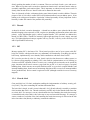
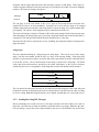
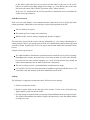
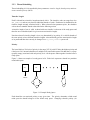
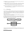
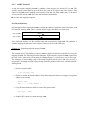
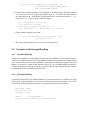
This is depicted in Fig. 1.1, where circles represent tasks, ovals clans (with their chief on top), and
arrows symbolise IPC. The bold arrow indicates the intended IPC, while the thin arrows indicate the
way the IPC is actually routed (provided all chiefs cooperate).
Figure 1.1: Message redirection by clans & chiefs
1.2.5 UIDs
A UID of a thread is that of its task plus the number of the thread within the task (called lthread or
local thread number). The UID of a task consists of the task number, some fields describing its place
in the task hierarchy, and a version number.
Both, tasks and threads are limited (on L4/MIPS there are 2048 tasks and within each task 128
threads). This means that tasks (or address spaces) and threads must be recycled. The -kernel ensures
uniqueness of task IDs by incrementing the version number whenever a task number is reused.
As far as threads are concerned, the L4 view is that threads do not die as long as their task exists,
they can only be blocked (waiting for IPC which will never arrive). This avoids the issue of lthread
uniqueness.
Obviously, both thread and task numbers are insufficient for a real multi-user operating system. This
means that an OS personality will in general need to map its own task and thread abstraction onto
L4’s. How this is done is up to the OS personality, L4 only provides the tools.
1.3 Resource allocation
As said earlier, the classical job of the OS is resource allocation. In a -kernel-based system, this is
left to the OS personality, the -kernel only provides the tools, and enforces security.
L4’s view of resources is simple: Each resource is allocated on a first-come-first-served basis. This
is by no means a free-for-all: The servers implementing OS personalities are started at boot time by
the -kernel. As they are the first running tasks, they have the chance to allocate all resources to
themselves before any “user” tasks exist. (As most resources are claimed via IPC the clans & chiefs
mechanism would anyway prevent direct access to resources by tasks which are not top-level.)
Initial servers must be contained in the L4 boot image, and must be identified as to be started up by
L4. This leaves responsibility for providing “sensible” servers to whoever creates the boot image.
Obviously, if you create the boot image you are in full control over what gets to run, and what is in
the system. Hence this approach is secure.
The same argument holds for “competition” between initial servers (OS personalities). This is under
full control of the system designer (and whoever creates the boot image) and therefore secure.
1.4 Organisation of this manual
Having presented the basic ideas on which L4 is based the next chapters will discuss L4 in detail.
Chapter 2 explains the IPC system call, which is by far the most complex one in L4. The remaining
L4 system calls are covered in Chapter 3. Chapter 4 discusses general use of the system.
Chapter 2
L4 IPC
2.1 IPC Overview
Message passing is the basic IPC mechanism in L4. It allows L4 threads to communicate via messages.
All L4 IPC is synchronous and unbuffered. Synchronous IPC requires an agreement between both the
sender and the receiver. The main implications of this agreement is that the receiver is expecting an
IPC and provides the necessary buffers. If either the sender or the receiver is not ready, then the other
party must wait. Unbuffered IPC reduces the amount of copying involved and is thus the key to high
performance IPC.
2.2 L4 IPC Messages
2.2.1 Message Data Types
Data can be transferred in three ways using L4 IPC.
1. In-line by-value data. A limited amount of such data is passed directly in registers (first 8 words
in MIPS R4k) with any remainder in a message buffer.
2. Strings. Arbitrary out-of-line buffers which are copied to the receiver.
3. Virtual memory mappings (by-reference data). Data transfer via mappings is described by
flex-pages (fpages). Alternatively, virtual memory can be granted: mapped to the receiver and
unmapped from the sender simultaneously.
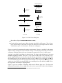
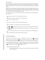
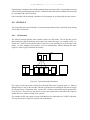
Figure 2.1 illustrates the difference between in-line by-value data and strings.
A flex-page is a contiguous region of virtual address space. A flex-page has the following properties.
Of size
bytes. The smallest size allowed for any fpage is the hardware page size.
6
Send Message Buffer
Send String
Dope
Sender copies
into buffer
Send String
m1
m2
m3
Kernel copies
Sender Message Buffer
string across
Kernel copies
into buffer
SEND
RECEIVE
m1
m2
Receive String
m3
Receive String
Dope
Receiver Message Buffer
Receiver retrieves
from buffer
Receive Message Buffer
(a) In-Line
(b) String
Figure 2.1: In-line Versus String Data
Base address aligned to
(
).
Contains all the mapped pages within the region described by the flex-page. That is, those
pages which belong to the specified region and which have been mapped into the sender’s
virtual address space. (For convenience, call these the valid pages).
Fpages are required for mapping and granting virtual memory. Fpages are specified by the mapper
and received by the mappee1 as part of an IPC message. For each fpage successfully received, the
valid pages within that fpage become part of (mapped or granted to) the receiver’s address space.
An fpage is specified by providing the values and . The fpage is then defined to be the region
[
,
]. In addition, a hot-spot, , is also required for the sender if the sender and receiver
specify fpages of different sizes. In such a case, the hot-spot specification is used to determine how
!
the mapping between the two different size fpages occurs: If
is the size of the larger, and the
#"
size of the smaller fpage, then the larger fpage can be thought of as being tiled by
fpages of the
smaller size. One of these is uniquely identified as containing the hot spot address (mod ). This is
the fpage which will actually be mapped/granted.
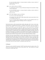
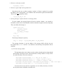
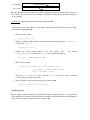
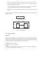
Figure 2.3 gives two examples of mappings which involve different fpage sizes. The figure also
illustrates the fact that the receiver’s fpage allows the receiver to specify the window where mappings
1
The terms mapper and mappee will be used in both mapping and granting contexts.
Flex-page
Mapper’s virtual adress space
Valid pages mapped/granted to mappee
Figure 2.2: Flex-page
are permitted to occur (greater security).
s=10
b=5
s=12
b=0
h=2 x 210 + offset
s=12
b=0
s=10
b=5
h=2 x 210 + offset
Figure 2.3: Fpage Mapping Example
A precise definition of the intuitive description above is now given for completeness. If the sender
defines its fpage as , , and the receiver defines its fpage as , then the mappings for the three
situations would be:
: mapping is
hot spot is not used
: mapping is
" the sender’s fpage is aligned around the hot-spot
: mapping is
" the receiver’s fpage is aligned around the hot-spot
As an explanation of the notation above,
catenating together, in the given order:
Bits 63 through to bit
Bits
" represents the bit address formed by con-
(inclusive) of .
through to bit (inclusive) of .
number of zeroes.
2.2.2 Messages
The message formats shown in this section are for L4/MIPS. On other platforms they are mostly very
similar.
Message Descriptors
A message descriptor is a pointer to the start of a message buffer2 or indication that the IPC is purely
register based. There are two types of message descriptors: one for sending and one for receiving
IPC.
The format of the send message descriptor is:
snd msg/4
md
A non-zero message descriptor address (snd msg) is interpreted as the start address of the sender’s
message buffer. A zero value indicates a purely register based IPC. Setting the -bit indicates that
the IPC includes mappings (i.e. fpages are present followed possibly by by-value data). A zero value
for the -bit indicates that the message contains only by-value data and no fpages. Setting the -bit
indicates that the IPC is deceiving.
The format of the receive descriptor is similar:
rcv msg/4
mo
If the -bit is not set, the message descriptor address (rcv msg) is interpreted as the start address of
the receiver’s message buffer, which may contain a receive fpage, indicating the caller’s willingness
to receive mappings or grants. Setting the -bit indicates that the caller is willing to accept fpage
2
See following description of a long message.
mappings but no long message, and has supplied the receive fpage directly as the rcv msg parameter
(there is no message buffer in this case). Setting the -bit will allow a receive from any sender (open
wait) while a zero value for the -bit allows receiving only from the specified sender.
Note that the the message descriptor addresses have had their least significant two bits removed. These
two bits are not needed as the message buffer must be word aligned.
Short And Long Messages
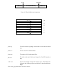
Every successful IPC operation will always copy at least eight dwords (for MIPS) to the receiver.
These eight dwords contain the first 64 bytes of a message’s in-line data3 and is referred to as the
short part of the message. The short message is transferred via registers (s0 . . . s7 on MIPS R4k) and
its format is:
s7
..
.
by-value data
s0
fpage descriptors
..
.
The presence of fpages is indicated by setting the -bit in the message descriptor. Processing of
fpages starts at the beginning of the message and continues until an invalid fpage is encountered. This
last dword and the remainder of the in-line data is interpreted as by-value data.
The long part of the message is optional and its presence is indicated by the message descriptor (snd
msg/recv msg). If present, it is a dword-aligned memory buffer pointed to by a message descriptor.
The buffer contains a three dword message header, followed by a number of mwords (the rest of
the in-line data), followed by a number of string dopes. The number of mwords (in 64-bit dwords,
excluding those copied in registers) and string dopes is specified in the message header.
The format for the long part of the message is:
message:
string dopes
+
mwords (fpage descriptors + by-value data)
+24
msg header
+0
The value of is determined by the number of mwords in the message as specified in the size dope of
the message header.
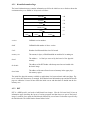
Message Header
The message header describes the format of the long message.
3
Section 2.2.1 describes the two types of in-line data: by-value data and fpage descriptors.
0 msg snd dope:
0
msg size dope:
dwords dwords
strings strings
msg rcv fpage option:
fpage
+16
+8
+0
The size dope defines the size of the dword buffer, in words, (and hence the offset of the string dopes
from the end of the header), and the number of string dopes in the long message.
The send dope specifies how many dwords and strings are actually to be sent. (Specifying send dope
values less than the size dope values makes sense when the caller is willing to receive more data than
it is sending.)
The receive fpage describes the address range in which the caller is willing to accept fpage mappings
or grants in the receive part (if any) of the IPC. As described in section 2.2.1, an fpage region is
defined by providing its base address, and size exponent, . Note that the hot-spot, , is provided by
the sender and hence not required as part of the receive fpage.
The fpage format is:
fpage 0
The base address can be given as
"!
least the hardware page size (
or
"!
$#
rather than just
bytes).
because fpages needs to be aligned to at
&% (' is one that' specifies the complete user address space (i.e. address space
A special case of an fpage
with base 0 and size
, where is the size of the kernel area).
fpage &%
('
0
0
64
Message mwords
The (possibly zero) message mwords follow directly after the message header and contain the rest of
the in-line data remaining after the short message. This in-line data is made up of a number (again,
possibly zero) of fpage descriptors followed by by-value data.
..
.
by-value data
mwords:
fpage descriptors
..
.
Fpage descriptors are expected in memory (the long message) only if the
-bit is set in the message
descriptor and all register data (the entire short message) consists of valid fpages. These fpage descriptors (together with those in the short message) are provided by the sender for memory mapping
purposes. The format of an fpage descriptor is:
snd fpage:
hot spot:
& 0
snd base
wg
The snd fpage is in the same format as the receive fpage in the message header except the least
significant two bits are no loner undefined. Setting the
bit will cause the fpage to be mapped
writable (rather than just read-only) and setting the bit causes the fpage to be granted (rather than
just mapped). The snd base is the mapping hot spot as described in section 2.2.1.
The kernel will interpret each pair of dwords of the in-line part (starting from the short message part
and continuing to the long message part, if present) as fpage descriptors until an invalid descriptor is
encountered. This and any further dwords are then interpreted as by value data.
Note that all in-line data is copied to the receiver, including any initial parts which are interpreted as
fpage descriptors.
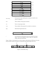
String Dopes
The last component making up a long message are string dopes. There can be zero or more string
dopes, with the exact number specified in the size dope of the message header. Each string dope
describes a region in memory where out-of-line data can be copied from (on an IPC send) and copied
to (on an IPC receive). The size and location of each string is specified in a string dope. The kernel
copies data from sender memory, specified by the sender string dopes, to the receiver’s memory,
specified by the receiver’s string dopes. Each string dope occupies four dwords and its format is:
rcv string size *snd string snd string size *rcv string
The first part of the string dope specifies the size and location of the string the caller wants sent to the
destination, while the second part specifies the size and location of a buffer where the caller is willing
to receive a string. Note that strings do not have to be aligned, and that their size is specified in bytes.
2.2.3 Sending/Receiving IPC Messages
Before considering how to send or receive it is necessary to decide what form of data is to be sent. In
particular, a decision must be made on whether to send data in-line or as strings. Both have the same
effect of making a copy of the sender’s data available to the receiver. The difference lies in efficiency
and appropriateness.
In-line data needs to be copied to a buffer first and must also be aligned. Thus the in-line option is
best for small amounts of data and is useful when some marshaling is required anyway. Sending short
strings as in-line data is more efficient as it avoids setting up string dopes and may also be done in
registers.
Strings avoid extra copying and can be located anywhere in memory (no alignment necessary) but
require buffers to be specified (via string dopes). Buffer specifications must also be consistent on both
the sender and the receiver end. In particular, the receiver must specify and expect to receive the (at
least) same number and size strings that the sender sends.
The C interface to L4’s system calls provides a number of IPC operations. They are differentiated in
the following ways:
Single send or receive versus a combined send and receive.
Receive from specific sender (closed) or any sender (open).
Deceiving or non-deceiving IPC.
To send or receive a message, certain parameters must be provided.
dest/src Identifier of message destination/source thread respectively.
snd msg/rcv msg Descriptor for long part of message, for send/receive part of IPC respectively.
snd reg/rcv reg Short part of message (artifact of C interface) for send/receive part of IPC respectively.
timeout Timeout specification. Used to ensure that a thread need not be blocked indefinitely.
result Variable to store the result status of the IPC operation.
L4 IPC Message Summary
In summary, an L4 IPC operation can have a send and a receive phase. The snd msg descriptor
describes what is to be sent, and the rcv msg descriptor describes what can be received. For the IPC to
be successful, the sender’s send descriptor and the receiver’s receive descriptor must be compatible.
Every successful IPC transfers some by-value data, the register (or short) part of the direct string
(8 bytes on ix86, 64 bytes on R4x00). In addition, the following may be transferred, provided the
snd msg descriptor says so, and the rcv msg descriptor allows it:
a bigger direct string, provided that:
– the send descriptor points to a message descriptor specifying a non-zero number of dwords
in the send dope, and
– the receive descriptor points to a message descriptor specifying a non-zero number of
dwords in the size dope, and
– there is no error;
one or more indirect strings, provided that:
– the send descriptor points to a message descriptor specifying a non-zero number of strings
in the send dope, and
– the receive descriptor points to a message descriptor specifying a non-zero number of
strings in the size dope, and
– there is no error;
one or more page mappings or grants, provided that
– the m-bit is set in the send descriptor, and
– the beginning of the sender’s direct string (starting with the register part) contains at least
one valid fpage descriptor, and
– the receive descriptor either has the form of a valid receive fpage and has the m-bit set, or
points to a message descriptor containing a valid receive fpage, and
– there is no error.
Note that the structure of the message descriptor and the string dopes make it easy to use the same
message header for sending and receiving (i.e., having the send descriptor and receive descriptor
point to the same address). The send dope specifies the size of the direct string and the number of
indirect strings for the send part (if any) of the IPC, while the size dope specifies the size of the buffer
for the direct string and the number of buffers for indirect strings for the receive operation (if any).
Note that using the same message descriptor for sending and receiving implies using the same buffer
for the direct sting. For indirect strings, each string dope specifies separately the location and size of
the buffers for the strings to be sent and received. If the IPC does not contain a send and a receive
part, then some of the information in the message header is not used. Similarly, if the send and receive
descriptors point to different message structures, some of the information in them is unused.
Obviously, if the same message descriptor is used for sending and receiving, receiving a direct string
(longer than the register part) will overwrite the string sent. Similarly, if the receive string of some
string dope points to the same address as the send string of the same or another string dope, then
receiving may overwrite some of the data which has been sent. However, as the send part of the IPC
is guaranteed to be concluded before any receive action takes place, this does not create any problems
if the sender does not need the data any more. The data to be sent will have been safely copied to the
receiver prior to the receive part of the IPC overwriting it on the caller’s end.
L4 Timeouts
Timeouts are used to control IPC operations. Each IPC operation specifies four timeout values. The
first two are with respect to the time before message transfer starts. These timeouts are no longer
relevant once message transfer starts.
receive timeout Specifies how long to wait for an incoming message. The receive operation fails if
the timeout period is exceeded before message transfer starts. The receive timeout is calculated
" as .
send timeout Specifies how long IPC should try to send a message. The send operation fails if the
timeout period is exceeded before message transfer starts. The send timeout is calculated as
" .
The other timeout values are used if a page fault occurs during an IPC operation. A page fault is
converted to an RPC to a pager by the kernel (see section 4.4). The page fault timeouts are with
respect to this RPC.
receive page fault timeout Used for both the send and receive timeouts of the page fault RPC when
a page fault occurs in the sender’s address space during an IPC. This value is set by the receiver
" and is calculated as
.
send page fault timeout Used for both the send and receive timeouts of the page fault RPC when a
page fault occurs in the receiver’s address space during an IPC. This value is set by the sender
" .
and is calculated as
There are two special timeout values: and 0. An infinite value means no timeout (i.e. possibly
indefinite blocking) and is specified by zero values of or . A zero timeout value represents non ). A maximum value for (
)
blocking IPC and is specified by zero values of (with
means that the IPC will fail if a page fault occurs.
L4 IPC Result Status
The status of each IPC operation is returned in a message dope with the following format.
0
mwords
strings
mwords Size in words of in-line data received (excluding register data).
str Number of strings received.
cc Condition code.
ec is an error code associated with the IPC. A zero value for ec implies a successful
IPC while a non-zero value means the IPC failed for some reason. On IPC failure, the actual
value of ec reports the reason for the failure (refer to reference manual). A common cause
of IPC failure results when the receiver expects less than what is really sent (i.e. the receive
buffer is too small, not providing enough receive strings, etc.). Note that the value of ec is also
delivered as the return value of the IPC procedures in the C library interface.
In the case of a truncated IPC the -kernel provides no information on how much data the
sender was trying to transmit.
Send/Receive Protocol
In the overview to this chapter, it was mentioned that the sender and receiver of an IPC must make
certain agreements. Sender and receiver must agree on the following points for the IPC:
The size of data to be copied.
The number and size of strings to be transferred.
Whether the IPC involves memory mappings (the presence of fpages).
The kernel does not provide the receiver with any information (e.g. size of data) concerning the incoming message. Thus, a user message protocol needs to be defined before hand to ensure agreement
on the above points. In general, the receiver can expect more from the sender than is actually sent but
not less.
Example of such a protocols are:
The sender marshals in-line data into a particular structure which the receiver will be expecting.
Depending on the structure and context, the receiver may not make use of the entire structure
but will receive the entire structure regardless (e.g. one field of the structure may identify the
context and consequently how the other fields are to be interpreted).
The receiver always receives a maximum number of maximum size strings.
Use two IPCs. The first one allows the sender to establish an agreement with the receiver. The
second IPC is the main message in the form established by the first IPC.
Sending
The following is a suggested procedure that can be followed to send a message.
1. Declare a result status variable.
2. Declare a register buffer for the short part of the message. If there is any in-line data copy
fpages and/or by-value data into the buffer.
3. If a long message is required, decide on a message format and determine the message descriptor.
The format is determined by the number of fpages, the amount of by-value data and the number
of strings to be sent.
(a) Fill in the message header.
(b) Copy in fpage descriptors (if any).
(c) Copy in by-value data (if any).
(d) Copy in (send) string dopes, one for each string.
4. Determine the thread id of the desired receiver thread.
5. Determine the desired timeout period.
6. Provide the parameters for one of the C interface procedures which allows for an IPC send.
Example 2.1 - Sending a short message
This example illustrates sending a short message. Assume the following conditions:
A single non-deceiving IPC send to a specific thread.
The receiver thread is .
Purely register based message (short message).
No timeout (indefinite blocking).
Then following the suggested procedure:
1. Declare a result status variable.
l4_msgdope_t result;
2. Declare a register buffer.
l4_ipc_reg_msg_t rmsg;
At this point, in-line data may be copied into the register buffer. For example (Note
that the entire buffer need not be used):
rmsg.reg[0] =
rmsg.reg[1] =
..
.
. . . ; /* a dword */
. . . ; /* a dword */
3. If a long message is required, decide on a message format.
Not required for a short message. To indicate that the message is purely message
based, use L4_IPC_SHORT_MSG (constant defined in ipc.h) for the message descriptor (snd msg
parameter).
4. Determine the thread id of the desired receiver thread.
The thread id of is given by SIGMA0_TID (constant defined in sigma0.h).
5. Determine the desired timeout period.
An infinite timeout period is provided by the constant L4_IPC_NEVER (defined in
types.h).
6. Provide the parameters for one of the C interface procedures.
For the given conditions the most appropriate C interface procedure is:
int l4_mips_ipc_send(l4_thread_t dest,
const void *snd_msg,
l4_ipc_reg_msg_t *snd_reg,
l4_timeout_t timeout,
l4_msgdope_t *result)
Filling in the parameters using information from steps 1-5 gives the desired system
call:
l4_mips_ipc_send(SIGMA0_TID, L4_IPC_SHORT_MSG,
&rmsg, L4_IPC_NEVER, &result);
Example 2.2 - Sending a long message
This example illustrates sending a long message that contains in-line as well as string data. Assume
the following conditions:
A single non-deceiving IPC send to a specific thread.
The receiver thread is .
Uses in memory message buffer (long message).
No fpages.
The in-line by-value data to be sent is stored in a variable with the following declaration:
dword_t buf[10];
One string is to be sent. The string is a null terminated character string called sbuf.
No timeout (indefinite blocking).
Again, following the suggested procedure:
1. Declare a result status variable.
l4_msgdope_t result;
2. Declare a register buffer and copy data into it.
Note that in this case, no direct copying is needed. All that is required is to provide
the address of the existing buffer - the C interface stub will load the registers from this buffer.
That is, the snd reg parameter will be:
(l4_ipc_reg_msg_t*) buf
3. If a long message is required, decide on a message format.
For this example, the message format will need to include a header, a two dword inline buffer (want to send a 10 dword buffer with first 8 dwords in registers) and one string dope.
Thus, can declare the message as:
typedef struct msg {
l4_msghdr_t msghdr;
dword_t buf[2];
l4_strdope_t strdope;
} msg_t;
msg_t lmsg;
The message descriptor is given by:
(msg_t *) (&lmsg & ˜(L4_IPC_SHORT_FPAGE | L4_IPC_DECEIT))
The message descriptor is just the address of the message buffer with the last two
bits masked out (ie. = 0 and = 0) to indicate a non-deceiving send operation with no
mappings.
(a) Fill in the message header.
The important point to note is that we need to send two dwords and one string and and
that no fpages are being received. Note also that the send dope and the size dope will be
the same since there is no receive involved.
lmsg.msghdr.snd_dope.msgdope = 0; /* zero out all fields */
lmsg.msghdr.snd_dope.md.dwords = 2; /* number of dwords to send */
lmsg.msghdr.snd_dope.md.strings = 1; /* number of strings to send */
lmsg.msghdr.size_dope.msgdope = lmsg.msghdr.snd_dope.msgdope; /* send & size dopes */
lmsg.msghdr.rcv_fpage.fpage = 0; /* not receiving any fpages */
Note that the the first and last expressions are not strictly necessary as the kernel only looks at the fields that are actually used.
(b) Copy in fpage descriptors (if any).
No fpages in this example.
(c) Copy in by-value data (if any).
No in-memory fpages but have two dwords of by-value data.
lmsg.buf[0] = buf[8];
lmsg.buf[1] = buf[9];
(d) Copy in (send) string dopes, one for each string.
One string dope describing one send string and no receive string.
lmsg.strdope.snd_size = strlen(sbuf); /* size of string in bytes */
lmsg.strdope.snd_str = sbuf; /* start of string */
lmsg.strdope.rcv_size = 0; /* no receive string */
lmsg.strdope.rcv_str = 0;
4. Determine the thread id of the desired receiver thread.
The thread id of is given by SIGMA0_TID (constant defined in sigma0.h).
5. Determine the desired timeout period.
An infinite timeout period is provided by the constant L4_IPC_NEVER (defined in
types.h).
6. Provide the parameters for one of the C interface procedures.
Once again, the most appropriate C interface procedure is:
int l4_mips_ipc_send(l4_thread_t dest,
const void *snd_msg,
l4_ipc_reg_msg_t *snd_reg,
l4_timeout_t timeout,
l4_msgdope_t *result)
Filling in the parameters using information from steps 1-5 gives the desired system
call:
l4_mips_ipc_send(SIGMA0_TID,
(msg_t *) (((dowrd_t)&lmsg) & ˜(3)),
(l4_ipc_reg_msg_t*) buf, L4_IPC_NEVER, &result);
Receiving
The following is a suggested procedure that can be followed to receive a message.
1. Declare a result status variable.
2. Declare a register buffer for the short part of the message.
3. If a long message is required, decide on a message format and determine the message descriptor.
The format is determined by the number of fpages, the amount of by-value data and the number
of strings to be received.
(a) Fill in the message header.
(b) Copy in (receive) string dopes, one for each string.
4. For a closed receive, determine the thread id of the desired sender thread. For an open receive,
declare a variable to store the thread id of the sender.
5. Determine the desired timeout period.
6. Provide the parameters for one of the C interface procedures which allows an IPC receive.
Example 2.3 - Receiving a short message
This example illustrates receiving a short message. Assume the following conditions:
A single non-deceiving IPC receive from any thread.
Purely register based message (short message).
No timeout (indefinite blocking).
Then following the suggested procedure:
1. Declare a result status variable.
l4_msgdope_t result;
2. Declare a register buffer.
l4_ipc_reg_msg_t rmsg;
3. If a long message is required, decide on a message format.
Not required for a short message. To indicate that the message is purely message
based, use L4_IPC_SHORT_MSG (constant defined in ipc.h) for the message descriptor (rcv msg
parameter).
4. For an open receive, declare a variable to store the thread id of the sender.
l4_threadid_t thrdid;
5. Determine the desired timeout period.
An infinite timeout period is provided by the constant L4_IPC_NEVER (defined in
types.h).
6. Provide the parameters for one of the C interface procedures.
For the given conditions the most appropriate C interface procedure is:
int l4_mips_ipc_wait(l4_thread_t *src,
const void *rcv_msg,
l4_ipc_reg_msg_t *rcv_reg,
l4_timeout_t timeout,
l4_msgdope_t *result)
Filling in the parameters using information from steps 1-5 gives the desired system
call:
l4_mips_ipc_wait(&thrdid, L4_IPC_SHORT_MSG,
&rmsg, L4_IPC_NEVER, &result);
Example 2.4 - Receiving a long message
This example illustrates receiving a long message that contains in-line as well as string data. Assume
the following conditions:
A single non-deceiving IPC receive from a specific thread. Assume the sender id has been
stored in a variable with the declaration:
l4_threadid_t senderid;
Uses in memory message buffer (long message).
No fpages.
10 dwords of in-line by-value data is to be received.
One string is to be received and stored in a character string buffer with the declaration:
char sbuf[MAX_BUF];.
where MAX_BUF is a constant.
No timeout (indefinite blocking).
The above assumptions made by the receiver actually defines the send/receive protocol. In particular,
the receiver expects at most 10 dwords of in-line data and one string of maximum size MAX_BUF. Note
that the sender may actually send less than the expected maximum (but not more). That is, there may
be less than 10 dwords of in-line data, no string data or a string smaller than the maximum size.
Then following the suggested procedure:
1. Declare a result status variable.
l4_msgdope_t result;
2. Declare a register buffer.
l4_ipc_reg_msg_t rmsg;
3. If a long message is required, decide on a message format.
For this example, the message format will need to include a header, a two dword inline buffer (want to receive a 10 dwords with first 8 dwords in registers) and one string dope.
Thus, can declare the message as:
typedef struct msg {
l4_msghdr_t msghdr;
dword_t buf[2];
l4_strdope_t strdope;
} msg_t;
msg_t lmsg;
The message descriptor is given by:
(msg_t *) (((dword_t)&lmsg) & ˜(3))
The message descriptor is just the address of the message buffer with the last two
bits masked out (ie. = 0 and = 0) to indicate a non-deceiving receive operation with no
mappings.
(a) Fill in the message header.
The important point to note is that we need to send two dwords and one string and and
that no fpages are being received. Note also that the size dope will be greater than the
send dope since there is no send involved.
lmsg.msghdr.size_dope.md.dwords = 2; /* number of dwords */
lmsg.msghdr.size_dope.md.strings = 1; /* number of strings */;
lmsg.msghdr.snd_dope = 0; /* no send (actually not needed)*/
(b) Copy in (receive) string dopes, one for each string.
One string dope describing one receive string and no send string.
lmsg.strdope.rcv_size = MAX_BUF; /* max bytes receive string */
lmsg.strdope.rcv_str = sbuf; /* start of string */
lmsg.strdope.snd_size = 0; /* no send string */
lmsg.strdope.snd_str = 0;
4. For a closed receive, determine the thread id of the desired sender thread.
The sender id is stored in the variable senderid
5. Determine the desired timeout period.
An infinite timeout period is provided by the constant L4_IPC_NEVER (defined in
types.h).
6. Provide the parameters for one of the C interface procedures.
For the given conditions the most appropriate C interface procedure is:
int l4_mips_ipc_receive(l4_thread_t src,
const void *rcv_msg,
l4_ipc_reg_msg_t *rcv_reg,
l4_timeout_t timeout,
l4_msgdope_t *result)
Filling in the parameters using information from steps 1-5 gives the desired system
call:
l4_mips_ipc_receive(senderid,
(msg_t *) ((dword_t)&lmsg) & ˜(3))
&rmsg, L4_IPC_NEVER, &result);
Note that the kernel does not tell you how much data was actually transmitted, this information must
either be explicitly encoded in the message or must be implicit in the protocol used between sender
and receiver.
2.3 Clans and Chiefs
2.3.1 Concepts
As described in Section 1.2.4, the clans and chiefs concept is one of the security mechanisms used by
L4 to allow protection policies to be implemented for its IPC message transfers.
Clans are created via a hierarchy of tasks. A task that creates another task becomes the chief of that
task and the set of tasks created by the chief forms the chief’s clan. Note that there is an implementation limit on the depth of the task hierarchy4 .
Security is provided through a number of restrictions and enforced protocols:
4
16 on R4k.
A task can only (directly) kill another task if that task is in its own clan or (indirectly) by killing
its chief.
Intra-clan messages (those that don’t cross clan boundaries) are delivered directly from sender
to receiver.
Inter-clan messages (those that cross clan boundaries), whether incoming or outgoing, are
routed from the sender to the sender’s chief instead of going to the specified receiver (in the
other clan). The chief has access to all parts of the message and can inspect and modify the
message before forwarding it or even suppress the message entirely. If forwarding the message,
the chief can make use of deceiving IPC so that the message will seemingly come from the
original sender.
Deceiving is direction-preserving: L4 will only allow the deceit if, on an outgoing message, the
virtual sender ID belongs (directly or indirectly) to the sender’s clan, or, on a message going
inside the clan the virtual sender is external to the sender’s clan. Furthermore, the receiver is
alerted to the deceit (via the -bit in the condition code returned from the call, see Section 2.2.3).
2.3.2 Usage and Cost
Some usage examples of clans and chiefs are:
network proxies Have a master clan for each node which receives all inter-node IPC and forwards
it.
system upgrade Have a clan for each system version. The chief for each clan can then translate
message formats between old and new versions as well as any other necessary adjustments.
user-based access permissions All tasks for a user are encapsulated in a single clan. The chief of
each clan (user) can implement arbitrary access protocols.
confinement Encapsulating a task in its own clan may be used to prevent it from leaking data or
mounting denial-of-service attacks.
The cost of supporting clans and chiefs is about four cycles per IPC. The cost of using clans and
chiefs is the product of the number of IPC operations and the number of chiefs involved. This last
point implies that the task hierarchy should be kept as flat as possible in the interests of efficiency.
Example 2.5 - Clans and chiefs
This example illustrates one possible inter-clan IPC scenario. It also demonstrates the use of
deceiving
IPC. Figure 2.4
shows the setup for this example. Task # is the
chief of task while task
%
%
is the chief of task .
wants to send
an inter-clan message to . The dashed line shows the
%
virtual
path
of
the
message
from
to
but
the actual path is shown by the normal% line. sends to
%
but the message is intercepted
by its chief, # . # tries to pass the % message to
but the message
is actually intercepted by
which finally forwards the message to . Deceiving IPC is used when
%
and
forwards their messages. The effect of this is that
receives as coming directly from .
#
will see the message it eventually
T2
T3
T4
T1
Figure 2.4: Clans and Chiefs Example
There are a few things to note before preceding with this example.
The use of deceiving IPC as in this example is not a mandatory part of using
the clans and chiefs
%
mechanism. Depending on the situation, the user may decide that
does not need to know
that the message was originally from or the identity of the original sender may be encoded
as part of the message. In either case, deceiving IPC need not be used.
However, deceiving is necessary to maintain proper
RPC semantics in the case of redirection:
%
(using l4_mips_ipc_call), the reply must
If attempts% an RPC-like communication with
for being able to receive it. See also Section 4.6.1 for an example.
come from
In terms of sending an inter-clan message and the actual path shown in figure 2.4, the only
to # (i.e. from the original sender to its
communication which must take
place is from
%
chief). The path from # to
and from
to
may never occur because these chiefs may
decide to suppress the message.
The thread
#
actually receiving the intercepted IPC is lthread 0 of the chief task.
Code fragments for each of the tasks may look as follows.
code:
is:
%
does not need to do anything special. It just attempts to send directly to
. So the code
l4_ipc_reg_msg_t msg;
l4_msgdope_t result;
l4_threadid_t t4id;
t4id =
. . . /* assign t2’s thread id */
l4_mips_ipc_send(t4id, L4_IPC_SHORT_MSG, &msg, L4_IPC_NEVER, &result);
..
.
code: # waits
to receive (actually intercept) a message from a client ( in this case) and passes
%
it on to
(after possibly inspecting and modifying the message) using a deceiving send with
as the virtual sender. So the code is:
#
l4_ipc_reg_msg_t msg;
l4_msgdope_t result;
l4_threadid_t clientid, t4id;
l4_mips_ipc_wait(&clientid, L4_IPC_SHORT_MSG, &msg, L4_IPC_NEVER, &result);
/* Inspect/modify message before forwarding */
t4id =
. . . /* assign t4’s thread id */
/* Send deceiving IPC to T4 with client as virtual sender */
l4_mips_ipc_send_deceiving(t4id, clientid, L4_IPC_SHORT_MSG, &msg,
L4_IPC_NEVER, &result);
..
.
%
code:
intercepts the message from # and directly forwards its message to . Note that
believes it receives its message directly from because of the deceiving IPC used by # . The
is similar to that for # and is not repeated.
code for
%
%
code:
does not need to know of the actual path taken by the message. It simply receives the
message and thinks (ignoring the -bit in the returned condition code) that it has come directly
from . So the code is:
l4_ipc_reg_msg_t msg;
l4_msgdope_t result;
l4_threadid_t senderid;
l4_mips_ipc_wait(&senderid, L4_IPC_SHORT_MSG, &msg, L4_IPC_NEVER, &result);
..
.
This code assumes that # and
know the destination of the IPC (it could be explicitly encoded in
the message or implicitly in the protocol). Practically this approach is most useful in such cases as
a server’s using a dedicated receiver thread which forwards requests to a number of worker threads
which then reply directly back to the client (using deceiving IPC).
A more appropriate way for a chief dealing with redirected IPC goes as follows:
#
code:
l4_ipc_reg_msg_t msg;
l4_msgdope_t result;
l4_threadid_t clientid, destid;
l4_mips_ipc_chief_wait(&clientid, &destid, L4_IPC_SHORT_MSG, &msg,
L4_IPC_NEVER, &result);
/* Inspect/modify message before forwarding */
/* Send deceiving IPC to intended destination with client as virtual sender */
l4_mips_ipc_send_deceiving(destid, clientid, L4_IPC_SHORT_MSG, &msg,
L4_IPC_NEVER, &result);
..
.
Chapter 3
Other L4 System Calls
3.1 Task Creation and Deletion
A task can be in either an active or an inactive state. Creating an active task creates a new address
space as well as the maximum number of threads for a task (128). Initially, all the threads of an active
task except for one (called lthread 0) are inactive. In contrast, an inactive task has no address space
and no threads (whether active or not) and thus consumes no resources.
The kernel only allows a certain number of tasks to be created on a first-come-first-served basis with
subsequent attempts to create a new task failing (see section 4.2). Thus, the purpose of creating an
inactive task is essentially to reserve the right to create an active task. Further, an inactive task can
be donated to another chief which effectively transfers the right to create an active task. The chief
of a new active task is the task that created it. A task created as inactive can have a new chief (task
donation).
Deleting a task removes the address space and all associated threads of the task. A task can only be
deleted by its chief or indirectly by (a chief higher up in the task hierarchy) deleting its chief.
Task creation and deletion is done by using the task_new system call. This system call first deletes
a (active or inactive) task and creates a new (active or inactive) one. If the task is created active it
gets the same task number (as provided in the dest parameter) but a different version number, hence
producing a different ID. An active task is created by providing a valid pager id to the system call
while a nil pager produces an inactive task.
Note that there is no separate task deletion system call as such. To kill a task, simply create a new
inactive task providing the id of the task to be killed to the task_new system call (as the dest parameter).
Creating an active task requires the caller to supply
a pager (the pager for the new task’s lthread 0, as well as the default pager for all further threads),
a start address and an initial stack pointer
a maximum scheduling priority (MCP), and
29
an exception handler (the handler for the new task’s lthread 0, as well as the default handler for
all further threads).
Creating an inactive task requires the caller to specify
a null pager (which identifies the new task as being inactive), and
a new chief for the task (which can be the same as the calling task, if not then the call donates
the task to the new chief).
3.2 Thread Related System Calls
3.2.1 Thread Manipulation
As mentioned already, an active task is created with a full set (128) of threads but with only one thread
active (lthread 0). A thread is activated by setting its instruction pointer (IP) and stack pointer (SP) to
valid values. Once active, a thread cannot be deactivated (other than by deleting its task). To stop a
thread from running it needs to be blocked on an IPC which will never succeed.
A thread’s instruction and stack pointers, along with its exception handler and pager, are set by manipulating the thread’s register values through the lthread_ex_regs system call. Providing the invalid
value (-1) for any of these to this system call will retain the old values. lthread_ex_regs also gives
back the old values of the instruction pointer, stack pointer, exception handler and pager. Thus, the
call can also be used to perform a (logical) thread switch (exchange registers of running thread with
saved a one, this supports thread management by an OS personality ) as well as save a thread’s current context (by providing invalid values only). A thread’s pending IPC’s are cancelled and those in
progress are aborted by this system call.
3.2.2 Release CPU
A thread can use the thread_switch system call to voluntarily release the CPU. The releasing thread
can specify a specific thread to which to donate its remaining time slice. If ready, the thread receiving
the donation obtains the remaining time of the other thread on top of its own time slice. Alternatively,
if the receiving thread is not ready or if the releasing thread does not specify a destination thread as
part of the system call, the caller’s remaining time slice is simply forfeited and normal scheduling
takes place immediately.
An important use of this system call is to implement user-level scheduling. The user-level scheduler
is (the only) thread running at highest priority, so it will be run by the -kernel whenever the kernel
scheduler is invoked. The user-level scheduler then selects the next thread it wants to run and donates
its time slice to it.
3.2.3 Thread Scheduling
Thread scheduling in L4 is controlled by three parameters: timeslice length, thread priority and maximum controlled priority (MCP).
Timeslice Length
Each L4 thread has a timeslice length associated with it. The timeslice value can range from 0 to
MAX_TIMESLICE and can vary between individual threads of a task. Each thread is scheduled for the
timeslice length currently associated with it. When a thread’s time quantum expires, the scheduler
selects the next runnable thread as described in the following section.
A timeslice length of zero is valid. A thread with zero timeslice is taken out of the ready queue and
therefore never scheduled (until it is given a non-zero timeslice length).
Note that a thread’s timeslice length is in no way determined by its priority. It is valid for threads of
the same priority to have different timeslice lengths. A thread initially gets the same timeslice length
as its parent and that value can only be changed via a l4_thread_schedule system call.
Priority
The kernel defines 256 levels of priority in the range [255..0] with 255 being the highest priority and
0 the lowest. L4’s internal scheduler uses multiple-level round-robin queues such that there is a queue
(possibly empty) associated with each priority level. All the queues taken together form the kernel’s
ready queue.
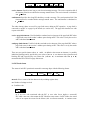
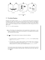
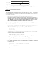
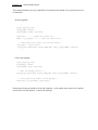
Figure 3.1 shows an example of a ready queue in L4. Each circle represents a thread in a particular
round robin queue.
255
254
0
EMPTY
Figure 3.1: Example Ready Queue
Each thread has an associated priority at any given time. The priority determines which round
robin queue the thread belongs to in the kernel ready queue. Changing a thread’s priority (via
l4_thread_schedule) will
change the queue it belongs to.
L4 priorities are absolute. On each scheduling event, the scheduler will always select the next thread to
run from the head of the highest priority queue that is currently non-empty. For example, in Figure 3.1,
the scheduler would take the thread at the head of the queue associated with priority 254.
Maximum Controlled Priority
Unlike the timeslice length and timeslice priority, the MCP is not thread based but rather task based.
The MCP of a task is specified at creation time (see Section 3.1) and all threads in the task will share
this MCP value.
Any thread can change another thread’s scheduling parameters (timeslice length and priority) by
invoking L4’s l4_thread_schedule system call under the right conditions. l4_thread_schedule
works if and only if src.mcp dest.prio AND src.mcp new prio. Otherwise, it will not change the
destination’s status but its effects on src are undefined.
Scheduling Parameter Inheritance
When an L4 task is created (by calling l4_task_new), only the MCP is specified but neither the time
slice length nor priority is given. Simlarily, creating an L4 thread (by calling l4_thread_ex_regs)
does not explicitly require any of the scheduling parameters to be provided. Thus there are implicit
scheduling parameter inheritance rules defined for new tasks and threads.
represents the value of given as a paramIn the following description of the inheritance rules represents the value of
eter in the relevant system call (l4_task_new or l4_thread_ex_regs),
in the creator task/thread and
represents the value of in the task/thread being created. is
one of either ,
or .
New task Only lthread 0 of the new task has its scheduling parameters defined. All other threads will
have their scheduling parameters defined when they are first activated (except for MCP which
is task based). So the actual inheritance rules for lthread 0 of the new task are:
New thread In this context, a thread is only considered new when it is first “created”. Recall from
Section 3.2.1 that the system call l4_thread_ex_regs can be used to activate an inactive thread,
to do a logical thread switch or just to get a thread’s state. For the current purposes, only the
first use of l4_thread_ex_regs is considered as “creating” a new thread. This distinction is
important because the following inheritance rules only apply when a new thread is created.
There is no change in scheduling parameters in the other two cases.
1
1
MCP is actually only defined for lthread 0 with all other threads in the task using the value from lthread 0.
One final issue must be considered as part of scheduling parameter inheritance. At boot time, (Section 4.3) starts up any programs that have been marked as initial servers in the kernel boot image
(see Section 4.1 for information on the L4 bootstrap and Section 4.3.2 for the boot image). has
maximum values for all its scheduling parameters and also calls l4_task_new (to create the initial
servers) with the MCP parameter set to maximum. Hence all initial servers will have maximum
values for their MCP and thread priority. This behaviour is sensible because initial servers should
form the OS and thus should be given maximum privileges.
L4 Scheduling System Call
The l4_thread_schedule system call allows setting (kernel) scheduling parameters of user threads.
It also returns thread states, in particular accumulated CPU time. The following restrictions and points
must be remembered when calling l4_thread_schedule:
For the call to be effective, the MCP condition described above must be satisfied.
The call cannot increase the destination thread’s priority over the caller task’s own MCP. That
is, the value of prio given in the param parameter must not exceed the caller’s MCP.
The new timeslice length of the destination can be set to any value2 within the interval [0,
MAX_TIMESLICE]. One way to set a thread to have MAX_TIMESLICE is to give the maximum
value that can be specified in timeslice format as the new timeslice length.
3.2.4 Obtaining Thread Identifiers
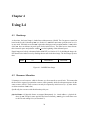
The id_nearest system call returns the ID of the thread that would really receive a message sent to a
specific thread. In particular, if the destination is:
outside invoker’s clan: Return ID of invoker’s own chief.
in same clan as invoker, or inside invoker’s clan: Return ID of destination thread.
in subclan of invoker’s clan: Return ID of chief (within own clan) of topmost subclan.
nil: Return invoker’s own thread ID. (This is the closest thing to a “null system call” in L4 and is
frequently used for benchmarking.)
Figure 3.2 shows the first three cases. Clan boundaries are shown as ovals and tasks are shown as
circles. An arrow is drawn from the sender to the destination and the shaded circle is the thread ID
that is returned by id_nearest when invoked by the sender.
2
Obviously, the timeslice length can only be specified with the accuracy allowed by the granularity of the timeslice
format. Moreover, not all representable values may be possible in the particular kernel, and the set of possible values may
depend on the priority of the target thread. L4 will round the specified value to the nearest possible value.
(a) Outside
(b) Inside
(c) In Subclan
Figure 3.2: id nearest
3.3 Revoking Mappings
Mappings can be recalled by using the fpage_unmap system call. The invoker specifies an fpage to be
revoked from all address spaces into which the invoker mapped directly or indirectly. The unmapping
can be done partially (revert to read-only) or completely (pages no longer part of the other address
spaces). As part of the unmapping, the invoker can optionally elect to remove the pages from its own
address space.
The fpage_unmap takes two paramters:
fpage: This the fpage to be unmapped subject to the map mask in the second parameter. As with
mapping and granting, the fpage specification designates all valid mapping within the address
space region defined by the fpage.
map mask: This determines how the unmap is performed by indicating:
1. The unmap operation - set fpage to read-only (L4_FP_REMAP_PAGE) or completely unmap
fpage (L4_FP_FLUSH_PAGE).
2. The unmap extent - apply the unmap operation to all other address spaces in which the
fpage has been mapped but not the original flex page (L4_FP_OTHER_SPACES) or apply the
unmap operation in every address space including the original (L4_FP_ALL_SPACES)
Note that the unmap operation and unmap extent are orthogonal and so both should be specified
(by combining the two attributes with a logical OR). The table below shows all the valid values
for map mask.
map mask
L4_FP_REMAP_PAGE |
L4_FP_OTHER_SPACES
L4_FP_FLUSH_PAGE |
L4_FP_OTHER_SPACES
L4_FP_REMAP_PAGE |
L4_FP_ALL_SPACES
L4_FP_FLUSH_PAGE |
L4_FP_ALL_SPACES
Description
Map fpage read-only in all other address spaces
in which the fpage has been mapped
Completely unmap the fpage in all other address spaces
in which the fpage has been mapped
Map fpage read-only
in all address spaces
Completely unmap the fpage
in all address spaces
3.4 An Example
Example 3.1 - Thread and task creation
This example illustrates how a thread can be made active and how to create an active (sub)task. First
a pager thread will be started and then a sub-task will be created using the newly started pager.
Assume we have the following declarations:
#define PAGERSTACKSIZE 1024
dword_t pager_stack[PAGERSTACKSIZE];
extern void pager(void); /* pager function */
extern void subtask(void); /* subtask function */
dword_t oip, osp; /* old insturction & stack pointers */
l4_thread_id_t excpt, page; /* exception handler and pager */
l4_thread_id_t pagerid, subtaskid, myid;
Now, to start a new thread the following steps are needed.
1. Get the id of own task.
myid = l4_myself();
Note that l4_myself is just a C interface procedure which uses the id_nearest L4 system call with a nil parameter.
2. Obtain an id for the new thread. Here we just use an lthread number one higher than that of the
calling thread. (This one better be unused!)
pagerid = myid; /* same task */
pagerid.id.lthread = 1; /* new thread */+
3. For this example, there is to be no change in exception handler and pager. That is, the new
thread is to have the same exception handler and pager as the thread that started it. Recall that
this is done by providing an invalid (-1) value for the exception handler and pager parameters
in the l4_thread_ex_regs system call.
excpt.ID = -1LL;
page.ID = -1LL;
4. Determine the new instruction pointer for the thread. In this case, it is just the entry address of
our pager function (i.e. pager).
5. Determine the new stack pointer for the thread. We can use any region of memory (in this
task’s address space) reserved for such a purpose. The stack starts from high memory and
“grows” downwards. Therefore out stack pointer is
&pager_stack[PAGERSTACK - 1]
6. Use l4_thread_ex_regs to start the new thread.
l4_thread_ex_regs(pagerid,
(dword_t) pager,
(dword_t) &pager_stack[PAGERSTACK - 1],
&excpt,
&page,
&oip,
&osp);
The second part of this example is to create a new task with the newly started thread as the pager for
the new task. The steps may be as follows:
1. Obtain a new task id. This can be done simply by picking any unused task id, here we assume
that the caller’s task is the last one in use so far. In general we need to manage task IDs.
subtaskid.ID = myid.ID;
subtaskid.id.task = 1; /* just pick an id higher than self */+
2. Determine the exception handler for the new task. For this example, the exception handler will
be set to be the thread that creates the new task (i.e. myid).
3. Determine the pager for the new task. For this example, the pager will be the previously started
thread (i.e. pagerid).
4. Determine the initial instruction pointer for the new task. In this case, it is just subtask.
5. Determine the maximum scheduling priority of the new task. Here we assume that this is
already set in a variable mcp.
6. Determine the initial stack pointer for the new task. Note the difference between this stack
pointer and that for creating a new thread. A new thread has the same address space as the
thread that started it (because they belong to the same task) but the new task will have a totally
new address space. By convention, the stack for a new task is placed in the high end of memory
though the exact place is up to the user. For this example, just use VA_SIZE (VA_SIZE is a
constant defined to be the size of the virtual address space).
7. Use l4_task_new to create the new task.
subtaskid = l4_task_new(subtaskid, mcp, VA_SIZE, &subtask,
pagerid, myid);
Chapter 4
Using L4
4.1 Bootstrap
At boot time, the kernel image is loaded into resident memory (RAM). The first process started (in
kernel mode) by the L4 bootstrap is (see Section 4.3). then in turn starts up all the initial servers
in user mode. All initial servers have registered as their pager and exception handler (i.e. is their
does not allocate any stack space for the initial servers. The initial servers must allocate
chief).
their own stack space and point the variable sp to the beginning of that allocated space.
Kernel images are built by a bootstrap linker called DIT (see Section 4.3.2). In building the image, the
DIT identifies the initial servers by marking them as such in the boot image. The boot image layout is
then:
header
L4
initial server...
other stuff
Figure 4.1: L4/MIPS Boot Image
4.2 Resource Allocation
L4 manages several resources which it allocates on a first-come-first-served basis. This means that
the first task to request for a particular resource will be granted it while all subsequent requests for the
same resource will fail. These resources can only be requested by initial servers (i.e. by tasks which
are direct members of ’s clan).
Specifically, the resources with this allocation policy are:
physical frames All physical frames are mapped idempotently (i.e. virtual address = physical address) by . Except for some special kernel reserved memory, only gives each frame once
to the first task asking for it (see Section 4.3).
38
device addresses Device access is memory mapped. Like physical memory, Pages containing device
addresses are mapped once to the first requester.
interrupts Each interrupt can have at most one interrupt handler. A thread installs itself as this
handler by following a set protocol (see Section 4.5.2). The first thread to do so for a particular
interrupt becomes the handler while all subsequent attempts by other threads will fail.
tasks Upon system initialisation, the full set of tasks (2048 on R4k) is created but in an inactive state.
Tasks are acquired using L4’s task_new system call. Once all available tasks have been given
out, no more tasks can be asked for (see Section 3.1).
4.3
- The Root Pager
An initial address space, called automatically exists after the system is booted. maps physical
memory (except for some kernel reserved regions) and is idempotent (all virtual addresses are the
same as the corresponding physical address). also acts as its own pager1 by mapping any frame
(writable) to the first task requesting it. Any further requests to for an already mapped frame is
ignored (a null reply is sent).
Figure 4.2 illustrates and how it is commonly used. The inclusion of in the kernel is specific to
L4/MIPS, is at user level in other implementations.
One of the first tasks that any OS personality needs to perform is to request all available frames from
so that has spent all its memory. This enables the OS to have full control of memory (other than
what is reserved by L4). The OS can then provide its own pager which maps memory to user tasks
(with the appropriate checks) in response to user page faults.
client
client
"initial server" (pager)
user
kernel
σ0
Figure 4.2: Part of the kernel reserved space contains the kernel information page and the DIT header page. These
special pages are mapped read-only upon request. Such mappings are part of the RPC protocol
(see Section 4.3.3).
1
Note that this is somewhat MIPS specific.
4.3.1 Kernel Information Page
The kernel information page contains information useful for the initial servers to find out about the
environment they were started in. Its layout is as follows:
dit header kernel memory size clock version kernel data
+40
+32
+24
+16
+8
build
“L4uK”
+0
version
L4/R4600 version number.
build
L4/R4600 build number of above version
clock
Number of millisecond ticks since L4 booted.
memory size
The amount, in bytes, of RAM installed on machine L4 is running on.
kernel
The address + 1 of last byte reserved by the kernel of low physical
memory.
dit header
The address of the DIT header which maps out what was loaded with
the kernel image.
kernel data
The address of the start of kernel reserved memory in the upper physical memory region.
The initial free physical memory available to applications lies between kernel and kernel data. Figure 4.3 shows how the memory is arranged. Note that the kernel information page and the DIT header
page are within the L4 reserved area while the initial servers and other data are loaded into the free
memory area.
4.3.2 DIT
DIT is a MIPS specific tool used to build kernel boot images. Like the L4 kernel itself, it has an
information page describing the layout of various programs and data that were part of the kernel
image. It consists of two parts, the initial header followed by zero of more file headers as specified by
the initial header. The initial headers format follows below.
Kernel
L4 Reserved
Kernel Data
Free Physical Memory
L4 Reserved
0
Figure 4.3: Physical Memory Arrangement
file end phdr num phdr size phdr off “dhdr” vaddr end
+20
+16
+12
+8
+4
+0
phdr off
The offset from the beginning of this header to where the file headers
start.
phdr size
The size of each of the file headers.
phdr num
The number of file headers that follow.
file end
The offset to the end of the kernel image file. For DIT internal use
only.
vaddr end
The end of currently used physical memory space. This includes the
L4 kernel and all other programs and data in the downloaded kernel
image.
Each of the program headers is laid out as follows.
entry size base flags
+28
+24
+20
+16
name string name string name string name string
+12
+8
+4
+0
name string
Null terminated string containing name of program or data file (truncated to 16 characters).
base
The base address of the program or data file.
size
The size of the program or data.
entry
The start address of the program if its executable, zero otherwise.
flags
Miscellaneous flags defined below.
r
r
If set the kernel runs this program as part of the initial servers upon
startup. If not set, the program or data has simply been loaded into
memory and has not been invoked.
Figure 4.4 shows a more detailed view of the boot image as described by the DIT header. Note that
the files Section is made up of initial servers followed by other data (possibly code or text).
phdr
off
DIT Header
vaddr
end
File
Headers
L4
Files
Figure 4.4: Detailed Boot Image
4.3.3
RPC Protocol
A task can request a mapping from by sending a short message (see Section 2.2.2) to . The
specific request is determined by up to the first two words in the register data of the request. If the
request is valid, sends a mapping to the requester. Note that only tasks in ’s clan (i.e. the initial
servers) can IPC directly to due to the clans and chiefs mechanisms.
provides four mapping categories:
Free Physical Memory
Physical frames can be requested from by sending the address of the frame as the first register word
in a short IPC message to . This is a special form of a page-fault RPC (see Section 4.4).
msg.w0 (s0)
address
msg.w1 (s1)
If the requested memory is in the available range and not previously mapped, will send back a
writable mapping for that frame to the requester, otherwise it will send a null reply.
Example 4.1 - Requesting physical memory from This example covers both sending a request to for a physical frame and successfully receiving the
mapping from . The following procedure illustrates explicit memory requests from but note that
the same can be achieved by just touching an unmapped page (i.e. read from or write to the page).
The advantage of just touching a page is decreased complexity but the cost is that error recovery is
not possible: An attempt to obtain a page already claimed by another initial server would livelock the
faulting thread.
1. Declare a register buffer.
l4_ipc_reg_msg_t msg;
2. Declare a variable to hold the address of the desired physical frame to be mapped. Assign that
address to the variable.
dword_t addr;
addr =
. . . ; /* some address */
3. Copy the frame address to the first word of the register buffer.
msg.reg[0] = addr;
4. Send the IPC request (in a short message) to .
l4_mips_send(SIGMA0_TID, L4_IPC_SHORT_MSG, &msg, L4_IPC_NEVER, &result);
result is
the usual result buffer (l4_msgdope_t result;).
5. Assuming all the steps are correct so far, can now wait to receive the mapping from .
l4_mips_receive(SIGMA0_TID,
(void *) ((dword_t) L4_IPC_SHORT_FPAGE |
(L4_WHOLE_ADDRESS_SPACE << 2)),
&msg, L4_IPC_NEVER, &result);
Note that the message reply from is expected to include a single page mapping. Recall from the message descriptor discussion in Section 2.2.2 that mappings can be received
as part of a short message by providing a receive fpage for the message descriptor parameter
(rcv msg) instead of the start address (or nil) of a message buffer.
The -bit needs to be set to indicate that fpages are to be received. This is done via a bit wise
OR with L4_IPC_SHORT_FPAGE (defined in ipc.h).
In this example, the mappings are made idempotent by specifying the whole address space as
the receive fpage. Again, recall that the fpage format for this is:
fpage &%
'
0
0
64
L4_WHOLE_ADDRESS_SPACE is defined to be 64 (in types.h) and with some thought, it can be
seen that L4_WHOLE_ADDRESS_SPACE << 2 corresponds exactly to the above fpage format. (See
the next example for a macro that helps perform this task.)
For added elegance, it is worth noting that the last two steps above can be combined by using the
appropriate C procedure. An IPC send to a particular thread followed immediately by a closed receive
from the same thread (usual RPC semantics) is facilitated by the l4_mips_ipc_call system call. The
last two steps above can then be replaced by a single step:
l4_mips_ipc_call(SIGMA0_TID, L4_IPC_SHORT_MSG, &msg,
(void *) ((dword_t) L4_IPC_SHORT_FPAGE |
(L4_WHOLE_ADDRESS_SPACE << 2)),
&msg, L4_IPC_NEVER, &result);
Kernel Information Page
Unlike free physical frames, the kernel information allows for multiple mappings to multiple
requesters. A request for the kernel information page can be made by providing a particular invalid
address (-3 on MIPS) as the first register word in a short IPC to .
msg.w0 (s0)
0xFFFFFFFFFFFFFFFD
msg.w1 (s1)
will respond to a request in the above format by mapping the kernel information page read-only to
the requester. The requester receives the address of the kernel information page in s0 assuming a one
to one mapping.
Example 4.2 - Requesting the Kernel Information Page from This example covers both sending a request to for the kernel information page and successfully
receiving the mapping from .
1. Declare a register buffer.
l4_ipc_reg_msg_t msg;
2. Declare a variable to hold the address of the kernel information page (the type l4_kernel_info
is defined in sigma0.h).
l4_kernel_info *kinfo;
3. Provide the correct invalid address as the first register word.
SIGMA0_KERNEL_INFO_MAP defined in sigma0.h can be used for this purpose.
The constant
msg.reg[0] = SIGMA0_KERNEL_INFO_MAP;
4. RPC the request to
.
l4_mips_ipc_call(SIGMA0_TID, L4_IPC_SHORT_MSG, &msg,
L4_IPC_MAPMSG(0, L4_WHOLE_ADDRESS_SPACE),
&msg, L4_IPC_NEVER, &result);
Note that L4_IPC_MAPMSG is a macro (defined in ipc.h) that can be used to construct
receive descriptors for short fpage IPCs.
5. Store the address of the kernel information page returned by .
kinfo = (l4_kernel_info *) msg.reg[0];
DIT Header page
also supports multiple mappings of the DIT header page to multiple requesters. A request for the
DIT header page is made by providing the DIT header address (obtained from the kernel information
page) as the first register word in a short IPC message to .
msg.w0 (s0)
dit header address
msg.w1 (s1)
will respond to a request in the above format by mapping the DIT header page read-only to the
requester.
Example 4.3 - Accessing the DIT Header Page
This example illustrates how information from the DIT header page can be obtained. Assuming that
the kernel information page has already been mapped (see previous example) there are two ways to
access the DIT header page:
Explicitly request a mapping of the DIT header page from before accessing it.
Access the DIT header page without an explicit mapping. This works because accessing the
DIT header page will cause a page fault if it has not already been mapped into the task’s address
space. handles the page fault (since the task must be within ’s clan otherwise it can’t IPC
to anyway) by mapping the DIT header page into the faulter’s address space.
The second method is simpler. The following example uses this method to access the DIT header page
and subsequently each file header.
1. Declare a variable to hold the address of the DIT header page and another variable to hold the
address of a file header (the types Dit_Dhdr and Dit_Phdr are defined in dit.h).
Dit_Dhr dhdr;
Dit_Phdr phdr;
2. Assign the address of the DIT header page (from the already mapped kernel information page see previous example) to the corresponding variable.
dhdr = (Dit_Dhdr *) (kinfo -> dit_hdr);
3. Assign the address of the first file header to the corresponding variable. This address can be
calculated by using the file header offset found in the DIT header page.
phdr = (Dit_Phdr *) ((int) dhdr + dhdr->d_phoff);
4. Cycle through each of the file headers. Recall that the number of file headers is also given in
the DIT header page.
for(i = 0; i < dhdr->d_phnum; i++, phdr++)
{
/* do some work */
..
.
}
Devices
A request for a device mapping can be made by providing a particular invalid address (-2 on MIPS) as
the first register word and the device address as the second register word in a short IPC to . Device
addresses are identified by values outside the RAM range.
msg.w0 (s0)
0xFFFFFFFFFFFFFFFE
msg.w1 (s1)
address
will respond by mapping address writable and uncacheable to the requester.
4.4 Page Fault Handling
A page fault occurs when a task tries to access (read from or write to) memory that has not already
been mapped into its virtual address space. A pager is a thread that handles page faults by determining
the actions to be taken in the event of a page fault (usually give a mapping for the faulting address to
the faulter).
When a new task/thread is created, a pager is registered with that task/thread. The registered pager is
then responsible for handling all the thread’s page faults. When a client thread triggers a page fault,
the L4 kernel intercepts the interrupt and sends an RPC to the pager on the client’s behalf. That is,
the kernel sends the client’s faulting address and instruction pointer in the first two words of a short
IPC message to the registered pager pretending that the IPC actually comes from the faulting thread.
w0 (s0)
fault address / 4
w1 (s1)
faulting user-level IP
Read page fault.
Write page fault.
The pager will receive the page fault message as if it were directly from the faulter. It can then respond
by sending an fpage mapping for the faulting address back to the faulter2 . The client does not actually
receive the pager’s mapping as the mapping is intercepted by the kernel on the client’s behalf. The
kernel restarts the client with the new mapping in place.
Figure 4.5 illustrates the RPC paging protocol described.
(see Section 4.3) is an example of a pager service. It is in fact the root pager because it handles
the initial address space and all mappings can be traced back to . The other type of pagers which
stem from are the external pagers. External pagers are user level threads which perform the task
of page fault handling for other threads. External pagers themselves originally obtain their mappings
from either or from an intermediate pager (which is just another external pager - see Figure 4.2).
2
This is standard page fault handling but a pager may implement an arbitrary policy, in particular, kill any clients that
attempt an invalid page access.
Effective RPC
client
fault
message
interrupt
pager
fault
mapping
L4
Figure 4.5: Page Fault RPC
A pager may send more than one page at a time, this allows implementing pre-paging.
The -kernel will ignore any attempts to map a page over an already existing mapping, any existing
mapping must first be removed (e.g. by using an le_fpage_unmap system call). An exception is
an attempt to replace an existing mapping by a mapping to the same frame. In this case, the writeprotection attribute of the mapping is taken from the present IPC operation (the -bit in the send fpage,
see Section 2.2.2). This allows the pager to change the mapping between read-only and writable.
Example 4.4 - A Simple Pager
This example presents the basic tasks that a simple user level pager needs to perform.
1. Assume the following declarations.
int r;
l4_ipc_reg_msg_t msg;
l4_threadid_t thrdid;
l4_msgdope_t result;
dword_t fault_addr;
l4_snd_fpage_t *fp;
2. First, the pager needs to wait for a page fault message from any client.
r = l4_mips_ipc_wait(&thrdid, L4_IPC_SHORT_MSG, &msg,
L4_IPC_NEVER, &result);
The faulter is recorded as the sender of the message (in thrdid) and the faulting address in the
first word of the register buffer.
3. The pager now needs to obtain a mapping of the faulting address for itself (if it does not already
have it) before it can pass the mapping on to the faulter. For this example, assume the pager
gets its mappings from .
fault_addr = (msg.reg[0] & (˜(dword_t) 3)); /* mask out lower bits */
msg.reg[0] = fault_addr | 2; /* request write mapping */
r = l4_mips_ipc_call(SIGMA0_TID, L4_IPC_SHORT_MSG, &msg,
L4_IPC_MAPMSG(0, L4_WHOLE_ADDRESS_SPACE),
&msg, L4_IPC_NEVER, &result);
4. Construct the send fpage descriptor for the mapping to the faulting client. The single mapping
to be sent is the same size as the single hardware page ( = 12) and has the fault address as
the send fpage base ( = fault address) and also the hot spot. Note that the function l4_fpage
(defined in types.h) can be used to construct an fpage.
fp = (l4_snd_fpage_t *) &msg.reg[0];
fp[0].snd_base = fault_addr;
fp[0].fpage = l4_fpage(fault_addr, 12, 1, 0);
fp[1].fpage.fpage = 0; /* invalid fpage as a terminator */
5. Finally, send the mapping to the client.
r = l4_mips_ipc_send(thrdid, L4_IPC_SHORT_FPAGE, &msg,
L4_IPC_NEVER, &result);
6. The pager returns to the start to wait for the next client page fault.
4.5 Exception And Interrupt Handling
4.5.1 Exception Handling
Exceptions are handled in a similar fashion to page faults (on L4/MIPS). As with registering pagers,
when a new task/thread is created, an exception handler thread is also registered with it. When a thread
raises an exception, the kernel’s interrupt handler sends an RPC to the thread’s registered exception
handler. The protocol is similar to that depicted in Figure 4.5. The exception handler can choose to
continue the thread that raised the exception by replying to the message. Ignoring the IPC will block
the faulting thread forever and thus effectively kill it.
4.5.2 Interrupt Handling
A thread can install itself as an interrupt handler for a particular interrupt by associating itself with
the interrupt. A thread that wants to associate itself with an interrupt needs to invoke a receive IPC
specifying the interrupt number as the sender (src parameter) and a zero timeout. That is:
l4_threadid_t sender;
l4_ipc_reg_msg_t msg;
l4_msgdope_t result;
sender =
. . . ; /* interrupt number */
l4_mips_ipc_receive(sender, L4_IPC_SHORT_MSG, &msg,
L4_IPC_TIMEOUT(0, 0, 0, 1, 0, 0), &result);
Each interrupt is assigned to the first thread that attempts to associate with it. Any attempt to associate
with an already associated interrupt will fail. A thread can dissociate itself as a handler for an interrupt
by associating with a NULL interrupt.
Once associated with an interrupt, a handler waits for interrupts by receiving with non-zero timeout.
4.6 OS On L4
This section discusses some of the basic issues and concepts that need to be considered when creating
an OS with L4 as the base.
4.6.1 OS Structure
The -kernel concept logically leans towards a client-server OS model. The OS provides servers
that perform the required operations upon request from clients (the pager is an example of this - see
Section 4.4). Each OS server and the entire OS itself are in fact operating at user level (same as the
client). As such, multiple OS personalities can exist simultaneously without affecting each other.
Figure 4.6 shows a typical L4-based OS structure.
client
client
devices
tty
SCSI
OS
pager
other OS
excpt
handler
syscall
handler
sub
system
L4
Figure 4.6: Typical L4-based OS Structure
In L4 terms, an OS may consist of many server threads in the same or separate tasks (i.e. single or
multiple task OS). One of the OS tasks will start up client processes making the OS chief of each of
the client processes. Clients then make “system calls” via library stubs which actually perform RPC
to an OS server. The OS server may choose to service the request itself or can redirect the request to
another OS server within or outside of its own task.
For example, the OS may contain a system call handler server which makes use of RPC redirection.
The steps involved in a single client system call would then be:
1. The client uses the library stub to send an RPC to the system call server and waits for a reply.
2. System call server forwards the request to another server via a deceiving send IPC operation
giving the client id as the virtual sender.
3. The subsystem performs the necessary operation and replies directly back to the client via a
deceiving send IPC operation giving the system call id as the virtual sender.
4. The client receives the reply to the original request as if it came directly from the system call
server.
Steps 2 and 3 above uses deceiving IPC to maintain RPC semantics. Figure 4.7 illustrates this RPC
redirection procedure.
client
IPC
deceiving IPC
OS
syscall
handler
deceiving
sub
system
IPC
Figure 4.7: RPC Redirection
4.6.2 Some Conventions
OS Startup
When the OS first starts, there are a few recommended tasks that it should perform before starting
any client processes. Basically, the OS needs to acquire all resources which are allocated on a first
request basis (to ensure resource control and prevent loss of resources to clients) as well as set up the
necessary structures. The tasks the OS should perform on startup include:
Register for all free interrupts.
Request all free memory from .
Request all pages containing device addresses (unless these are requested by separate driver
tasks, which must then also be initial servers)
Set up data structures for memory management (reserve space for free lists, frame table, client
page tables etc.)
Acquire all inactive tasks (i.e. use l4_task_new on all inactive task IDs).
Start other server threads (if any).
Start device driver threads (if any).
Set up service data structures (i.e. TCBs, file system, etc.).
After the OS has completed all the preliminary tasks, it can start up one or many client tasks. The OS
may choose to donate some of its acquired tasks to any of the user (sub)tasks.
Note that the OS itself is just a user level L4 task and thus can be interrupted and scheduled out.
This fact, together with multi-threading, makes it essential to have concurrency control on all OS data
structures.
Initial servers are started up by L4 and therefore cannot receive a stack address from their parent.
They must therefore initialise their own stack. This is normally done by using special startup code for
initial servers (“crtS”) which initialises the stack pointer to the top of a static array.
Clients
After start up, the OS will be either waiting for a client request or actually handling a client request.
After the preliminaries, it is the job of the OS to start the client tasks (else the OS will have nothing to
do!). But where does the OS look to find clients to start? The answer is that it is a matter of convention
and is decided by the OS designer. Some common options are:
OS starts up first non-initial server executable in the boot image. (Recall that the files section of
the boot image is composed of initial servers followed by other data - see Figure 4.4. Non-initial
servers are part of the other data).
First non-executable item in the boot image contains a list of initial client tasks.
The OS looks for an executable with a predefined name in the boot image.
After the client has been started, it will want to make system calls as a normal part of its operations.
Again, there needs to be some convention defined to let clients know where to send their system call
RPCs (i.e. need to know id of OS’s system call server). Some common options are:
First thing the client does is an open receive. The OS (or any other task that started the client)
follows the protocol by sending a message to the client containing its own identity or the identity
of another server. Note that this client startup protocol can be hidden in startup code (“crt0”).
Client could send all system call RPCs to . Then the clans and chiefs mechanism will ensure
that the chief of the client task will intercept the message. The chief can then reply pretending
to be via a deceiving send IPC.
Example 4.5 - Client Startup Protocol
This example illustrates one way in which the OS can disclose the identity of its system call server id
to client tasks.
OS code fragment:
..
.
l4_ipc_reg_msg_t msg;
l4_msg_dope_t result;
l4_threadid_t subid, syscallid;
. . . ; /* system call server id */
subid = l4_task_new( . . . ); /* start the client task */
syscallid =
/* Send system call server id to the new client */
msg.reg[0] = syscallid.ID;
l4_mips_ipc_send(subid, L4_IPC_SHORT_MSG, &msg, L4_IPC_NEVER, &result);
..
.
Client code fragment:
l4_ipc_reg_msg_t msg;
l4_msgdope_t result;
l4_threadid_t OSid, syscallid;
/* Wait for message from OS */
l4_mips_ipc_wait(&OSid, L4_IPC_SHORT_MSG, &msg, L4_IPC_NEVER, &result);
/* Store system call server id from message */
syscallid = (l4_threadid_t) msg.reg[0];
..
.
Note that the client gets both the id of the OS (implicitly - as the sender in the open receive) and the
system call server id (explicitly - as part of the message).
Bibliography
[BH70]
Per Brinch Hansen. The nucleus of a multiprogramming operating system. Communications of the ACM, 13:238–250, 1970.
[CB93]
J. Bradley Chen and Brian N. Bershad. The impact of operating system structure on memory system performance. In Proceedings of the 14th ACM Symposium on OS Principles,
pages 120–133, Asheville, NC, USA, December 1993.
[EHL97]
Kevin Elphinstone, Gernot Heiser, and Jochen Liedtke. L4 Reference Manual — MIPS
R4x00. School of Computer Science and Engineering, University of NSW, Sydney
2052, Australia, December 1997. UNSW-CSE-TR-9709. Latest version available from
http://www/cse/unsw.edu.au/˜disy/.
[HHL 97] Herrmann Härtig, Michael Hohmuth, Jochen Liedtke, Sebastian Schönberg, and Jean
Wolter. The performance of -kernel-based systems. In Proceedings of the 16th ACM
Symposium on OS Principles, pages 66–77, St. Malo, France, October 1997. ACM.
[Lie92]
Jochen Liedtke. Clans & chiefs. In 12. GI/ITG-Fachtagung Architektur von Rechensystemen, pages 294–305, Kiel, 1992. Springer Verlag.
[Lie93]
Jochen Liedtke. Improving IPC by kernel design. In Proceedings of the 14th ACM
Symposium on OS Principles, pages 175–88, Asheville, NC, USA, December 1993.
[Lie95]
Jochen Liedtke. On -kernel construction. In Proceedings of the 15th ACM Symposium
on OS Principles, pages 237–250, Copper Mountain, CO, USA, December 1995.
[Lie96]
Jochen Liedtke. Towards real microkernels. Communications of the ACM, 39(9):70–77,
September 1996.
[RTY 88] Richard Rashid, Avadis Tevanian, Jr., Michael Young, David Golub, Robert Baron, David
Black, William J. Bolosky, and Jonathan Chew. Machine-independent virtual memory
management for paged uniprocessor and multiprocessor architectures. IEEE Transactions on Computers, C-37:896–908, 1988.
[WCC 74] W. Wulf, E. Cohen, W. Corwin, A. Jones, R. Levin, C. Pierson, and F. Pollack. HYDRA:
The kernel of a multiprocessor operating system. Communications of the ACM, 17:337–
345, 1974.
54