1
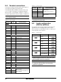
Cat. No. I127-EN-00B
SX-V
High power Variable Frequency Inverters
Model: SX-V
400 V Class Three-Phase Input 90 kW to 800 kW
690 V Class Three-Phase Input 90 kW to 1000 kW
USER’S MANUAL
O M RO N S X- V
I N ST RU C TI O N M A N UA L - E N G L I SH
Software version 4.21
Document number: I 127-E N -0 0B
Document name : Omron SX inverter manual
Edition : Preliminary V0.97
Date of release: 03-11-2009
© Copyright Omron Electronics 2009
Omron retains the right to change specifications and illustrations in the
text, without prior notification. The contents of this document may not
be copied without the explicit permission of Omron Electronics.
1
Safety Instructions
Precautions severity
Follow this advice for good practice. Not following can lead to
malfunctioning or possibility of injury to the user.
High risk of malfunction or damage to the inverter or installation,
possibility of injury to the user.
Earth and grounding. Potential risk of electric shock or damage to
inverter or installation.
High inmediate risk of serious injury to the user, inverter or
installation.
Risk if manipulated by unqualified personnel
WARNINGS AND CAUTIONS
Instruction manual
Read throuhfully this instruction manual before using the Variable Speed Drive, VSD
Mains voltage selection
The variable speed drive may be ordered for use with the mains voltage range listed below.
SX-V-4: 230-480 V
SX-V-6: 500-690 V
IT Mains supply
The variable speed drives can be modified for an IT mains supply, (non-earthed neutral),
check manual and contract your supplier in case of doubt.
EMC Regulations
In order to comply with the EMC Directive, it is absolutely necessary to follow the installation
instructions. All installation descriptions in this manual follow the EMC Directive.
Transport
To avoid damage, keep the variable speed drive in its original packaging during transport.
This packaging is specially designed to absorb shocks during transport.
Handling the inverter
Installation, commissioning, dismounting, taking measurements, etc, of or on the variable
speed drive may only be carried out by personnel technically qualified for the task. The
installation must be carried out in accordance with local standards.
Omron SX inverter manual
1
Condensation
If the variable speed drive is moved from a cold (storage) room to a room where it will be
installed, condensation can occur. This can result in sensitive components becoming damp.
Do not connect the mains voltage until all visible dampness has evaporated.
Grounding the inverter
Be sure to ground the unit. Not doing so may result in a serious injury due to an electric
shock or fire.
Power factor capacitors for improving cos
Remove all capacitors from the motor and the motor outlet.
Incorrect connection
The variable speed drive is not protected against incorrect connection of the mains voltage,
and in particular against connection of the mains voltage to the motor outlets U, V and W.
The variable speed drive can be damaged in this way.
Stop motion mechanical device to ensure safety
The inverter controls the motor electrically, but has no means to stop it mechanically under
some types of failures... In applications where mechanical stop is required to a degree of
safety, a safety assurance study should be carried out to determine the need of additional
mechanical braking devices.
Braking resistor and regenerative braking units
In case the application needs it, be sure to use a specified type of braking resistor/regenerative braking unit. In case of a braking resistor, install a thermal relay that monitors the temperature of the resistor. Not doing so might result in a burn due to the heat generated in the
braking resistor/regenerative braking unit. Configure a sequence that enables the Inverter
power to turn off when unusual overheating is detected in the braking resistor/regenerative
braking unit.
Electric protection of installation
Take safety precautions such as setting up a molded-case circuit breaker (MCCB) or fuses
that matches the Inverter capacity on the power supply side. Not doing so might result in
damage to property due to the short circuit of the load.
Wiring works and servicing the inverter
Wiring work must be carried out only by qualified personnel. Not doing so may result in a
serious injury due to an electric shock. Do not dismantle, repair or modify this product if
you’re not authorised and qualified for it. Doing so may result in an injury.
DC-link residual voltage
After switching off the mains supply, dangerous voltage can still be present in the VSD.
When opening the VSD for installing and/or commissioning activities wait at least 10 minutes. In case of malfunction a qualified technician should check the DC-link or wait for one
hour before dismantling the VSD for repair.
Opening the variable speed drive cover
Only qualified technician can open the inverter. Always take adequate precautions before
opening the inverter. Although the connections for the control signals and the switches are
isolated from the main voltage, do not touch the control board when the variable speed drive
is switched on.
Do not manipulate inverter under power
Do not change wiring , put on or take off optional devices or replace cooling fans while the
input power is being supplied. Doing so may result in a serious injury due to an electric
shock. Inspection of the Inverter must be conducted after the power supply has been
turned off. Not doing so may result in a serious injury due to an electric shock. The main
power supply is not necessarily shut off even if the emergency shutoff function is activated.
2
Omron SX inverter manual
Precautions to be taken with a connected motor
If work must be carried out on a connected motor or on the driven machine, the mains voltage must always be disconnected from the variable speed drive first. Wait at least 5 minutes
before starting work.
Short-circuits
The Inverter has high voltage parts inside which, if short-circuited, might cause damage to
itself or other property. Place covers on the openings or take other precautions to make sure
that no metal objects such as cutting bits or lead wire scraps go inside when installing and
wiring.
Earth leakage current
This variable speed drive has an earth leakage current which does exceed 3.5 mA AC.
Therefore the minimum size of the protective earth conductor must comply with the local
safety regulations for high leakage current equipment which means that according the
standard IEC61800-5-1 the protective earth connection must be assured by one of following conditions:
1. Use a protective conductor with a cable cross-section of at least 10 mm2 for copper (Cu)
or 16 mm2 for aluminium (Al).
2. Use an additional PE wire, with the same cable cross-section as the used original PE and
mains supply wiring.
Residual current device (RCD) compatibility
This product cause a DC current in the protective conductor. Where a residual current
device (RCD) is used for protection in case of direct or indirect contact, only a Type B RCD is
allowed on the supply side of this product. Use RCD of 300 mA minimum.
Voltage tests (Megger)
Do not carry out voltage tests (Megger) on the motor, before all the motor cables have been
disconnected from the variable speed drive.
Precautions during Autoreset
When the automatic reset is active, the motor may restart automatically provided that the
cause of the trip has been removed. If necessary take the appropriate precautions.
Heat warning
Be aware of specific parts on the VSD having high temperature. Do not touch the Inverter fins,
braking resistors and the motor, which may become too hot during the power supply and for some
time after the power shut-off. Doing so may result in a burn.
Do not Operate the inverter with wet hands
Do not operate the Digital Operator or switches with wet hands. Doing so may result in a
serious injury due to an electric shock.
Omron SX inverter manual
3
4
Omron SX inverter manual
Contents
1.
I n t r o d u c t i o n . .. .. .. .. .. .. . . . . . . . . . . . . . . . . . . . . 7
1.1
1.2
1.3
1.4
1.4.1
1.5
1.5.1
1.6
1.6.1
1.6.2
Delivery and unpacking .......................................... 7
Using of the instruction manual............................. 7
Ordering codes ........................................................ 8
Standards ................................................................ 8
Product standard for EMC ...................................... 8
Dismantling and scrapping.................................. 10
Disposal of old electrical and electronic equipment
10
Glossary ................................................................ 10
Abbreviations and symbols.................................. 10
Definitions............................................................. 10
2.
M o u n t i n g . .. .. .. .. .. .. .. .. ... .. .. .. .. .. .. .. . 1 1
6.
Applications ............................... 33
2.1
2.2
2.2.1
2.2.2
2.3
2.3.1
2.3.2
Lifting instructions................................................
Stand-alone units .................................................
Cooling ..................................................................
Mounting schemes...............................................
Cabinet mounting.................................................
Cooling ..................................................................
Mounting schemes...............................................
6.1
6.1.1
6.1.2
6.1.3
6.1.4
Application overview ............................................. 33
Cranes.................................................................... 33
Crushers................................................................. 33
Mills........................................................................ 34
Mixers .................................................................... 34
7.
M ai n F ea t u r e s . .. . . . . . . . . . . . . . . . . . . . . . . . . . 3 5
3.
I n st a lla t io n .. .. .. .. .. .. .. ... .. .. .. .. .. .. .. . 1 7
3.1
3.2
3.2.1
3.2.2
3.3
3.4
3.5
3.5.1
3.5.2
3.6
3.7
Before installation................................................
Cable connections................................................
Mains cables ........................................................
Motor cables.........................................................
Connect motor and mains cables .......................
Cable specifications.............................................
Stripping lengths ..................................................
Dimension of cables and fuses...........................
Tightening torque for mains and motor cables..
Thermal protection on the motor ........................
Motors in parallel .................................................
7.1
7.1.1
7.1.2
7.1.3
7.1.4
7.1.5
7.1.6
7.2
7.3
7.4
7.5
7.5.1
Parameter sets...................................................... 35
One motor and one parameter set ...................... 36
One motor and two parameter sets..................... 36
Two motors and two parameter sets ................... 36
Autoreset at trip .................................................... 37
Reference priority.................................................. 37
Preset references.................................................. 38
Remote control functions ..................................... 38
Performing an Identification Run ......................... 40
Using the Control Panel Memory.......................... 40
Load Monitor and Process Protection [400] ....... 40
Load Monitor [410]............................................... 40
8.
E M C a n d Ma c h i n e Di r e c t i v e .. .. .. .. 4 5
4.
G et t ing St arte d .. .. .. .. ... .. .. .. .. .. .. .. . 2 3
4.1
4.1.1
4.1.2
4.2
4.3
4.3.1
4.3.2
4.3.3
4.3.4
4.4
4.4.1
4.4.2
4.4.3
4.4.4
4.4.5
Connect the mains and motor cables.................
Mains cables ........................................................
Motor cables.........................................................
Using the function keys .......................................
Remote control.....................................................
Connect control cables ........................................
Switch on the mains.............................................
Set the Motor Data...............................................
Run the VSD .........................................................
Local control .........................................................
Switch on the mains.............................................
Select manual control..........................................
Set the Motor Data...............................................
Enter a Reference Value......................................
Run the VSD .........................................................
8.1
8.2
EMC standards...................................................... 45
Stop categories and emergency stop .................. 45
9.
O pe r a t i o n v i a t h e C o n t r o l P a n e l .. 4 7
5.
Control Connections ................... 27
9.1
9.2
9.2.1
9.2.2
9.2.3
9.2.4
9.2.5
9.2.6
9.3
9.3.1
9.4
9.5
9.6
9.7
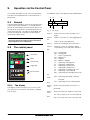
General .................................................................. 47
The control panel .................................................. 47
The display............................................................. 47
Indications on the display..................................... 48
LED indicators ....................................................... 48
Control keys........................................................... 48
The Toggle and Loc/Rem Key .............................. 48
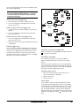
Function keys ........................................................ 50
The menu structure .............................................. 50
The main menu ..................................................... 50
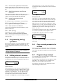
Programming during operation ............................ 51
Editing values in a menu ...................................... 51
Copy current parameter to all sets ...................... 51
Programming example.......................................... 51
5.1
Control board........................................................ 27
Omron SX inverter manual
11
12
13
13
14
14
14
17
17
17
17
19
20
20
20
21
21
21
23
23
23
24
24
24
24
24
25
25
25
25
25
25
25
5.2
5.3
Terminal connections ........................................... 28
Inputs configuration
with the switches........................................................ 28
5.4
Connection example ............................................. 29
5.5
Connecting the Control Signals............................ 30
5.5.1
Cables .................................................................... 30
5.5.2
Types of control signals ........................................ 30
5.5.3
Screening............................................................... 30
5.5.4
Single-ended or double-ended connection? ....... 31
5.5.5
Current signals ((0)4-20 mA)................................ 32
5.5.6
Twisted cables....................................................... 32
5.6
Connecting options ............................................... 32
5
10.
S er i a l c o m m u n i c a t i o n .. .. .. .. .. .. .. .. . 5 3
10.1
10.2
10.3
10.4
10.5
10.5.1
10.6
Modbus RTU .........................................................
Parameter sets.....................................................
Motor data ............................................................
Start and stop commands ...................................
Reference signal ..................................................
Process value .......................................................
Description of the EInt formats ...........................
11.
Functional Description ................ 59
11.1
11.1.1
11.1.2
11.2
11.2.1
11.2.2
11.2.3
11.2.4
11.2.5
11.2.6
11.2.7
11.2.8
11.3
11.3.1
11.3.2
11.3.3
11.3.4
11.3.5
11.3.6
11.3.7
11.3.8
11.3.9
11.3.10
11.3.11
11.4
11.4.1
11.4.2
11.5
11.5.1
11.5.2
11.5.3
11.5.4
11.5.5
11.5.6
11.6
11.6.1
11.6.2
11.6.3
11.6.4
11.6.5
11.7
11.7.1
11.7.2
11.7.3
11.8
11.8.1
Preferred View [100]............................................ 59
1st Line [110]....................................................... 59
2nd Line [120] ..................................................... 60
Main Setup [200] ................................................. 60
Operation [210].................................................... 60
Remote Signal Level/Edge [21A]........................ 63
Mains supply voltage [21B]................................. 64
Motor Data [220] ................................................. 64
Motor Protection [230] ........................................ 69
Parameter Set Handling [240] ............................ 72
Trip Autoreset/Trip Conditions [250].................. 74
Serial Communication [260] ............................... 81
Process and Application Parameters [300] ....... 83
Set/View Reference Value [310] ........................ 84
Process Settings [320] ........................................ 84
Start/Stop settings [330] .................................... 89
Mechanical brake control.................................... 92
Speed [340].......................................................... 95
Torques [350]....................................................... 97
Preset References [360] ..................................... 99
PI Speed Control [370] ...................................... 100
PID Process Control [380] ................................. 101
Pump/Fan Control [390] ................................... 105
Crane Option [3A0] ............................................ 111
Load Monitor and Process Protection [400] .... 114
Load Monitor [410] ............................................ 114
Process Protection [420]................................... 118
I/Os and Virtual Connections [500].................. 119
Analogue Inputs [510] ....................................... 119
Digital Inputs [520] ............................................ 126
Analogue Outputs [530] .................................... 128
Digital Outputs [540] ......................................... 132
Relays [550] ....................................................... 134
Virtual Connections [560].................................. 135
Logical Functions and Timers [600] ................. 136
Comparators [610] ............................................ 136
Logic Output Y [620] .......................................... 140
Logic Output Z [630] .......................................... 142
Timer1 [640] ...................................................... 143
Timer2 [650] ...................................................... 145
View Operation/Status [700] ............................ 146
Operation [710].................................................. 146
Status [720] ....................................................... 148
Stored values [730] ........................................... 151
View Trip Log [800] ............................................ 152
Trip Message log [810]...................................... 152
6
53
53
53
54
54
54
54
11.8.2
11.8.3
11.9
11.9.1
Trip Messages [820] - [890] .............................
Reset Trip Log [8A0] ..........................................
System Data [900].............................................
VSD Data [920] ..................................................
153
153
154
154
12.
Tr o u b l e s h o o t i n g , D i a g n o s e s a n d M a i n tenance 157
12.1
12.2
12.2.1
12.2.2
12.2.3
12.2.4
12.3
Trips, warnings and limits..................................
Trip conditions, causes and remedial action ...
Technically qualified personnel.........................
Opening the variable speed drive .....................
Precautions to take with a connected motor ...
Autoreset Trip .....................................................
Maintenance ......................................................
13 .
O ptions .. .. .. .. .. .. ... .. .. .. .. .. .. .. .. .. .. 1 6 3
13.1
13.2
13.3
13.4
13.5
13.6
13.7
13.8
13.9
13.10
13.11
Options for the control panel.............................
PC Tool software ................................................
Brake chopper....................................................
I/O Board ............................................................
Output coils ........................................................
Serial communication and fieldbus ..................
Standby supply board option.............................
Safe Stop option.................................................
Crane option board ............................................
Encoder...............................................................
PTC/PT100 .........................................................
14 .
Te c h n ic al D a ta .. ... .. .. .. .. .. .. .. .. .. .. 1 6 9
14.1
14.2
14.3
14.4
14.5
14.6
14.6.1
14.6.2
14.7
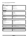
Electrical specifications related to model ........ 169
General electrical specifications....................... 171
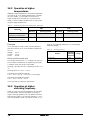
Operation at higher temperatures .................... 172
Dimensions and Weights................................... 173
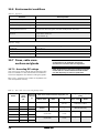
Environmental conditions.................................. 174
Fuses, cable cross-sections and glands........... 174
According IEC ratings ......................................... 174
Fuses and cable dimensions according NEMA ratings
177
Control signals.................................................... 179
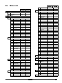
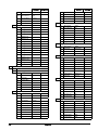
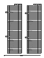
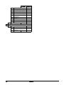
15.
M e n u L i s t . .. .. .. .. . . . . . . . . . . . . . . . . . . . . . . . 1 8 1
157
158
158
158
158
158
161
163
163
163
164
164
164
164
165
167
167
167
Omron SX inverter manual
1.
Introduction
Omron SX-V is used most commonly to control and
protect pump and fan applications that put high
demands on flow control, process uptime and low
maintenance costs. It can also be used for e.g. compressors and blowers. The used motor control
method is V/Hz-control. Several options are available,
listed in , that enable you to customize the variable
speed drive for your specific needs.
Users
This instruction manual is intended for:
• installation engineers
• maintenance engineers
• operators
• service engineers
Motors
The variable speed drive is suitable for use with standard 3-phase asynchronous motors. Under certain
conditions it is possible to use other types of motors.
Contact your supplier for details.
1.1
Delivery and unpacking
Check for any visible signs of damage. Inform your
supplier immediately of any damage found. Do not
install the variable speed drive if damage is found.
The variable speed drives are delivered with a template
for positioning the fixing holes on a flat surface. Check
that all items are present and that the type number is
correct.
1.2
Using of the instruction
manual
Within this instruction manual the abbreviation “VSD”
is used to indicate the complete variable speed drive
as a single unit.
Check that the software version number on the first
page of this manual matches the software version in
the variable speed drive.
With help of the index and the contents it is easy to
track individual functions and to find out how to use
and set them.
The Quick Setup Card can be put in a cabinet door, so
that it is always easy to access in case of an emergency.
Omron SX inverter manual
Introduction
7
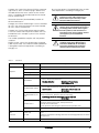
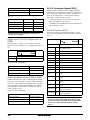
1.3
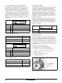
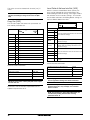
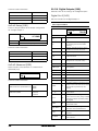
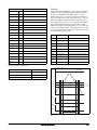
Ordering codes
Options
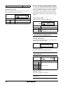
Fig. 1 and Fig. 2 give examples of the ordering code
numbering used on SX variable speed drives. With this
code number the exact type of the drive can be determined. This identification will be required for type specific information when mounting and installing. The
code number is located on the product label, on the
front of the unit.
1
2
3
4
SX-
D
6
160- E
Fig. 1
5
6
7
VF
-OPTIONS
Type code number
Position n.chars
Configuration
1
3
Inverter family name “SX-”
2
1
Protection class
“A”=IP20
“B”=IP00
“D”=IP54
3
1
Voltage Class
“4”=400V
“6”=690V
4
4
Power in kW
(normal duty rating)
“090-”=90kW
...
“1K0-”=1000kW
5
1
Market
“E”=Europe
6
6
Control type
“V”=V/Hz
“F”=Direct Torque
Control
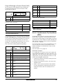
0 to 13
All options with single letter (see table
below)
7
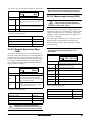
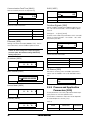
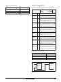
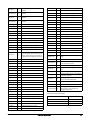
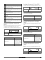
Fig. 2
“-”+letters A to X
Coated boards
“?” = No coating
“G” = Coated boards
Option board
position 1
“?” = No option
“H” = Crane I/O
“I” = Encoder
“J” = PTC/PT100
“K” = Extended I/O“
Option board
position 2
“?” = No option
“I” = Encoder
“J” = PTC/PT100
“K” = Extended I/O“
Option board
position 3
“?” = No option
“I” = Encoder
“J” = PTC/PT100
“K” = Extended I/O“
Option board
Fieldbus
position 4
“?” = No option
“L” = DeviceNet
“M” = Profibus-DP
“N” = RS232/485
“O” = EtherNet Modbus TCP
Liquid Cooling
“?” = No Liquid Cooling
“P” = Liquid Cooling
Standard
“?” = IEC
“Q” = UL
Marine
“?” = No marine option
“R” = Marine option included
Cabinet input
options
“?” = No cabinet input options
“S” = Main switch included
“T” = Main contactor included
“U” = Main switch + contactor included
Cabinet output
options
“?” = No cabinet output options included
“V” = dU/dt filter included
“W” = dU/dt filter + Overshoot clamp
included
“X” = Sinusfilter included
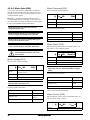
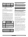
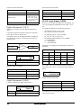
Option letters
Options
Control panel
1.4
Letter (“?” means no character)
“?” = Standard control panel (Std.PPU)
“A”= Blank control panel (Blank PPU)
“?” = Standard EMC inside (Category C3)
Built-in EMC filter “B” = IT-Net (filter disconnected from
ground)
Built-in brake
chopper
“?” = No brake chopper or DC-connection
included
“C” = Brake chopper & DC-connection
included
“D” = Only DC-connection included
Standby power
supply
“?” = Not included
“E” = Standby power supply included
Safe stop
“?” = Not included
“F” = Safe stop included
Control type
“V”=V/Hz
“F”=Direct Torque Control
8
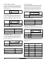
Letter (“?” means no character)
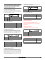
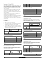
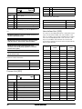
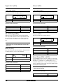
Standards
The variable speed drives described in this instruction
manual comply with the standards listed in Table 1.
For the declarations of conformity and manufacturer’s
certificate, contact your supplier for more information.
1.4.1
Product standard for EMC
Product standard EN(IEC)61800-3, second edition of
2004 defines the:
First Environment (Extended EMC) as environment
that includes domestic premises. It also includes
establishments directly connected without intermediate transformers to a low voltage power supply network that supplies buildings used for domestic
purposes.
Introduction
Omron SX inverter manual
Category C2: Power Drive System (PDS) of rated voltage<1.000 V, which is neither a plug in device nor a
movable device and, when used in the first environment, is intended to be installed and commissioned
only by a professional.
By using the optional “Extended EMC” filter the VSD
fulfils requirements according to category C2,
WARNING: In a domestic environment this
product may cause radio interference, in
which case it may be necessary to take
adequate additional measures.
Second environment (Standard EMC) includes all
other establishments.
Category C3: PDS of rated voltage <1.000 V, intended
for use in the second environment and not intended
for use in the first environment.
Category C4: PDS or rated voltage equal or above
1.000 V, or rated current equal to or above 400 A, or
intended for use in complex systems in the second
environment.
WARNING: The standard VSD, complying with
category C3, is not intended to be used on a
low-voltage public network which supplies
domestic premises; radio interference is
expected if used in such a network. Contact
your supplier if you need additional
measures.
The variable speed drive complies with the product
standard
EN(IEC) 61800-3:2004 (Any kind of metal screened
cable may be used). The standard variable speed drive
is designed to meet the requirements according to
category C3.
CAUTION: In order to comply fully with the
standards stated in the Manufacturer’s
Declaration ANNEX IIB, the installation
instructions detailed in this instruction
manual must be followed to the letter.
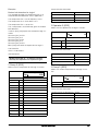
Table 1
!
Standards
Market
European
All
Standard
Description
Machine Directive
98/37/EEC
EMC Directive
2004/108/EEC
Low Voltage Directive
2006/95/EC
WEEE Directive
2002/96/EC
EN 60204-1
Safety of machinery - Electrical equipment of machines
Part 1: General requirements.
Machine Directive:
Manufacturer’s certificate
acc. to Appendix IIB
EN(IEC)61800-3:2004
Adjustable speed electrical power drive systems
Part 3: EMC requirements and specific test methods.
EMC Directive:
Declaration of Conformity and
CE marking
EN(IEC)61800-5-1 Ed.
2.0
Adjustable speed electrical power drive systems Part 5-1.
Safety requirements - Electrical, thermal and energy.
Low Voltage Directive: Declaration of Conformity and
CE marking
IEC 60721-3-3
Classification of environmental conditions. Air quality chemical vapours, unit in
operation. Chemical gases 3C1, Solid particles 3S2.
Optional with coated boards
Unit in operation. Chemical gases Class 3C2, Solid particles 3S2.
UL508C
UL Safety standard for Power Conversion Equipment
90 A only
USA
UL and UL
UL 840
Russian
GOST R
Omron SX inverter manual
UL Safety standard for Power Conversion Equipment power conversion equipment.
Insulation coordination including clearances and creepage distances for electrical equipment.
For all sizes
Introduction
9
1.5
Dismantling and scrapping
The enclosures of the drives are made from recyclable
material as aluminium, iron and plastic. Each drive
contains a number of components demanding special
treatment, for example electrolytic capacitors. The circuit boards contain small amounts of tin and lead. Any
local or national regulations in force for the disposal
and recycling of these materials must be complied
with.
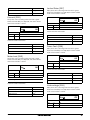
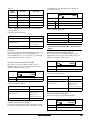
1.5.1
1.6.2
In this manual the following definitions for current,
torque and frequency are used:
Table 3
Disposal of old electrical and
electronic equipment
This information is applicable in the European Union
and other European countries with separate collection
systems.
This symbol on the product or on its packaging indicates that this product shall be treated according to
the WEEE Directive. It must be taken to the applicable
collection point for the recycling of electrical and electronic equipment. By ensuring this product is disposed
of correctly, you will help prevent potentially negative
consequences for the environment and human health,
which could otherwise be caused by inappropriate
waste handling of this product. The recycling of materials will help to conserve natural resources. For more
detailed information about recycling this product,
please contact the local distributor of the product.
1.6
1.6.1
Definitions
Definitions
Name
Description
Quantity
IIN
Nominal input current of VSD
ARMS
INOM
Nominal output current of VSD
ARMS
IMOT
Nominal motor current
ARMS
PNOM
Nominal power of VSD
kW
PMOT
Motor power
kW
TNOM
Nominal torque of motor
Nm
TMOT
Motor torque
Nm
fOUT
Output frequency of VSD
Hz
fMOT
Nominal frequency of motor
Hz
nMOT
Nominal speed of motor
rpm
ICL
Maximum output current
ARMS
Speed
Actual motor speed
rpm
Torque
Actual motor torque
Nm
Sync
speed
Synchronous speed of the motor
rpm
Glossary
Abbreviations and symbols
In this manual the following abbreviations are used:
Table 2
Abbreviations
Abbreviation/
symbol
Description
DSP
Digital signals processor
VSD
Variable speed drive
CP
Control panel, the programming and presentation unit on the VSD
EInt
Communication format
UInt
Communication format
Int
Communication format
Long
Communication format
The function cannot be changed in run mode
10
Introduction
Omron SX inverter manual
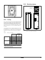
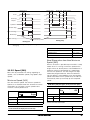
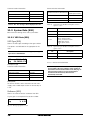
2.
Mounting
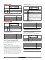
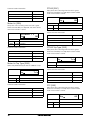
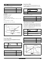
Models 4090 to 4132 and 6090 to 6250
This chapter describes how to mount the VSD.
Before mounting it is recommended that the installation is planned out first.
Load: 56 to 74 kg
• Be sure that the VSD suits the mounting location.
• The mounting site must support the weight of the
VSD.
• Will the VSD continuously withstand vibrations
and/or shocks?
• Consider using a vibration damper.
• Check ambient conditions, ratings, required cooling air flow, compatibility of the motor, etc.
• Know how the VSD will be lifted and transported.
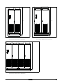
2.1
Lifting instructions
Note: To prevent personal risks and any damage to the
unit during lifting, it is advised that the lifting methods
described below are used.
Fig. 3
Omron SX inverter manual
Mounting
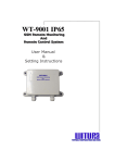
Lifting model 4090-4132 and 6090-6250
11
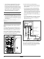
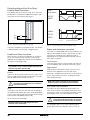
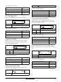
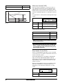
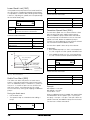
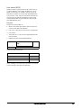
Models 4160 to -4800 and 6315 to 61K0
Lifting eye
Fig. 4
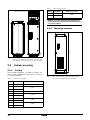
Remove the roof plate.
Terminals for roof fan
unit supply cables
A
Fig. 6
2.2
Lifting VSD model 4160-4800 and 6315-61K0
Stand-alone units
DETAIL A
The VSD must be mounted in a vertical position
against a flat surface. Use the template (delivered
together with the VSD) to mark out the position of the
fixing holes.
Fig. 5
12
Remove roof unit
Mounting
Omron SX inverter manual
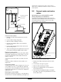
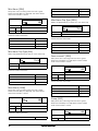
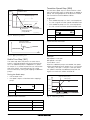
2.2.2
Mounting schemes
Membrane cable
gland M60
240
284,5
275
Ø16(3)
30
10
120
Ø9(6x)
22,5
922,50
Cooling
952,50
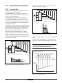
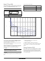
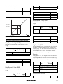
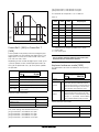
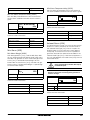
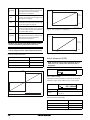
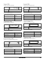
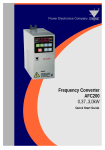
2.2.1
Mounting models 4090-4800 and 6090-61K0
925
Fig. 7
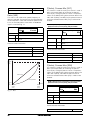
Fig. 7 shows the minimum free space required around
the VSD for the models 4090-4800 and 6090-61K0 in
order to guarantee adequate cooling. Because the
fans blow the air from the bottom to the top it is advisable not to position an air inlet immediately above an
air outlet.
The following minimum separation between two variable speed drives, or a VSD and a non-dissipating wall
must be maintained. Valid if free space on opposite
side.
Table 4
314
Fig. 8
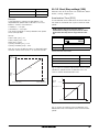
SX-V (400V): Model 4090 including cable interface
for mains, motor and communication
Mounting and cooling
SX-V
(mm)
SX-V-wall, wall-one
side
(mm)
a
b
c
d
a
b
c
d
4090-4132
6090-6250
4160-4800
6315-61K0
cabinet
200
200
0
0
100
100
0
0
100
0
0
0
100
0
0
0
NOTE: When a 4160-4800 or 6315-61K0 model is placed
between two walls, a minimum distance at each side of
200 mm must be maintained.
Omron SX inverter manual
Mounting
13
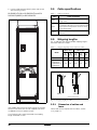
Table 5
22.50
300
Frame
SX-V Model
K
4630 - 4800
K69
6710 - 61K0
30
Ø16(3x)
4800
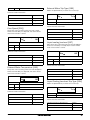
Mounting schemes
922,50
952,50
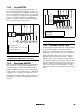
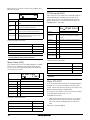
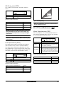
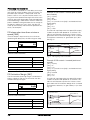
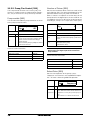
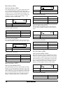
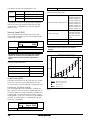
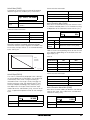
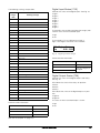
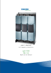
2.3.2
925
Flow rate [m3/hour]
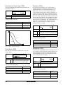
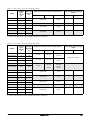
NOTE: For the models 4450-4500 and 6800-61K0 the
mentioned amount of air flow should be divided equally
over the two cabinets.
344,5
335
10
150
Ø9(x6)
Cable dimensions 27-66 mm
Flow rates cooling fans
2330
314
Fig. 9
2.3
2.3.1
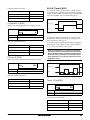
SX-V (400V): Model 4110 to 4132 (F)
SX-V (690V): Model 6090 to 6160 (F69) including
cable interface for mains, motor and communication
Cabinet mounting
Cooling
If the variable speed drive is installed in a cabinet, the
rate of airflow supplied by the cooling fans must be taken into consideration.
Table 5
Flow rates cooling fans
Frame
SX-V Model
Flow rate [m3/hour]
E
4090
510
F
4110 - 4132
F69
6090 - 6160
G
4160 - 4200
H
4220 - 4250
H69
6200 - 6355
I
4315 - 4400
I69
6450 - 6500
J
4450 - 4500
J69
6600 - 6630
14
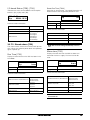
600
600
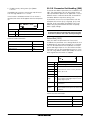
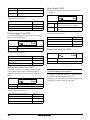
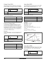
Fig. 10 SX-V (400V): Model 4160 to 4250 (G and H)
SX-V (690V): Model 6200 to 6355 (H69)
800
1020
1600
2400
3200
Mounting
Omron SX inverter manual
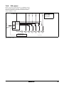
2330
2330
600
1200
1000
600
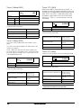
Fig. 12 SX-V (400V): Model 4450 to 4500 (J)
SX-V (690V): Model 6600 to 6630 (J69)
Fig. 11 SX-V (400V): Model 4315 to 4400 (I)
SX-V (690V): Model 6450 to 6500 (I69)
2330
600
2000
Fig. 13 SX-V (400V): Model 4630 to 4800 (K)
SX-V (690V): Model 6710 to 61K0 (K69)
Omron SX inverter manual
Mounting
15
16
Mounting
Omron SX inverter manual
3.
Installation
The description of installation in this chapter complies
with the EMC standards and the Machine Directive.
Select cable type and screening according to the EMC
requirements valid for the environment where the VSD
is installed.
3.1
Connect the mains cables according to the next figures. The VSD has as standard a built-in RFI mains filter that complies with category C3 which suits the
Second Environment standard.
Table 6
Before installation
Read the following checklist and think through your
application before installation.
Mains and motor connection
L1,L2,L3
PE
Mains supply, 3 -phase
Safety earth (protected earth)
U, V, W
Motor earth
Motor output, 3-phase
• External or internal control.
(DC-),DC+,R
• Long motor cables (>100m), refer to section Long
motor cables.
• Motors in parallel, refer to menu [213].
NOTE: The Brake and DC-link Terminals are only fitted if
the Brake Chopper Option is built-in.
• Functions.
• Suitable VSD size in proportion to the motor/application.
WARNING: The Brake Resistor must be
connected between terminals DC+ and R.
• Mount separately supplied option boards according to the instructions in the appropriate option
manual.
If the VSD is temporarily stored before being connected, please check the technical data for environmental conditions. If the VSD is moved from a cold
storage room to the room where it is to be installed,
condensation can form on it. Allow the VSD to
become fully acclimatised and wait until any visible
condensation has evaporated before connecting the
mains voltage.
3.2
3.2.1
Brake resistor, DC-link
connections (optional)
Cable connections
Mains cables
WARNING: In order to work safely, the mains
earth must be connected to PE and the
motor earth to
.
3.2.2
Motor cables
To comply with the EMC emission standards the variable speed drive is provided with a RFI mains filter. The
motor cables must also be screened and connected
on both sides. In this way a so-called “Faraday cage”
is created around the VSD, motor cables and motor.
The RFI currents are now fed back to their source (the
IGBTs) so the system stays within the emission levels.
Dimension the mains and motor cables according to
local regulations. The cable must be able to carry the
VSD load current.
Recommendations for selecting motor
cables
Recommendations for selecting mains
cables
• Use screened cables according to specification in
table 7. Use symmetrical shielded cable; three
phase conductors and a concentric or otherwise
symmetrically constructed PE conductor, and a
shield.
• To fulfil EMC purposes it is not necessary to use
screened mains cables.
• When the conductivity of the cable PE conductor is
<50% of the conductivity of the phase conductor, a
separate PE conductor is required.
• Use heat-resistant cables, +60C or higher.
• Dimension the cables and fuses in accordance
with local regulations and the nominal current of
the motor. See table 42, page 174.
• Use heat-resistant cables, +60C or higher.
• The litz ground connection see fig. 15, is only necessary if the mounting plate is painted. All the variable speed drives have an unpainted back side and
are therefore suitable for mounting on an unpainted
mounting plate.
Omron SX inverter manual
• Dimension the cables and fuses in accordance
with the nominal output current of the motor. See
table 42, page 174.
• Keep the motor cable between VSD and motor as
short as possible.
Installation
17
• The screening must be connected with a large
contact surface of preferable 360 and always at
both ends, to the motor housing and the VSD
housing. When painted mounting plates are used,
do not be afraid to scrape away the paint to obtain
as large contact surface as possible at all mounting
points for items such as saddles and the bare
cable screening. Relying just on the connection
made by the screw thread is not sufficient.
NOTE: It is important that the motor housing has the
same earth potential as the other parts of the machine.
• The litz ground connection, see fig. 16, is only necessary if the mounting plate is painted. All the variable speed drives have an unpainted back side and
are therefore suitable for mounting on an unpainted
mounting plate.
Pay special attention to the following points:
• If paint must be removed, steps must be taken to
prevent subsequent corrosion. Repaint after making connections!
• The fastening of the whole variable speed drive
housing must be electrically connected with the
mounting plate over an area which is as large as
possible. For this purpose the removal of paint is
necessary. An alternative method is to connect the
variable speed drive housing to the mounting plate
with as short a length of litz wire as possible.
• Try to avoid interruptions in the screening wherever
possible.
• If the variable speed drive is mounted in a standard
cabinet, the internal wiring must comply with the
EMC standard. Fig. 15 shows an example of a
VSD built into a cabinet.
Connect the motor cables according to U - U, V - V
and W - W.
VSD built into cabinet
NOTE: The terminals DC-, DC+ and R are options.
RFI-Filter
(option)
Mains
Switches between the motor and the
VSD
If the motor cables are to be interrupted by maintenance switches, output coils, etc., it is necessary that
the screening is continued by using metal housing,
metal mounting plates, etc. as shown in the Fig. 15.
VSD
Motor
Metal EMC cable glands
Output coil (option)
Litz
Screened cables
Fig. 16 shows an example when there is no metal
mounting plate used (e.g. if IP54 variable speed drives
are used). It is important to keep the “circuit” closed,
by using metal housing and cable glands.
Unpainted mounting plate
Metal connector housing
Mains
(L1,L2,L3,PE)
Screen connection
of signal cables
Metal coupling nut
Motor
Brake resistor
(option)
Fig. 15 Variable speed drive in a cabinet on a mounting plate
Fig. 16 shows an example when there is no metal
mounting plate used (e.g. if IP54 variable speed drives
are used). It is important to keep the “circuit” closed,
by using metal housing and cable glands.
PE
Motor cable
shield connection
Fig. 14 Screen connection of cables.
18
Installation
Omron SX inverter manual
maintenance switches) only switch if the current is
zero. If this is not done, the VSD can trip as a result of
current peaks.
VSD
RFI-Filter
Mains
3.3
Metal EMC cable glands
Screened cables
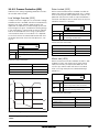
SX-D4090-EV (V) to SX-D4132-EV and SXD6090-EV(690V) to SX-D4160-EV
To simplify the connection of thick motor and mains
cables to the VSD model SX-D4090-EV to SX-D4132EV and SX-D6090-EV to SX-D4160-EV the cable
interface plate can be removed.
Metal housing
Brake
resistor
(option)
Connect motor and mains
cables
Output
coils
(option)
Metal connector housing
Metal cable gland
Motor
Mains
Fig. 16 Variable speed drive as stand alone
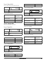
Connect motor cables
1. Remove the cable interface plate from the VSD
housing.
2. Put the cables through the glands.
3. Strip the cable according to Table 8.
4. Connect the stripped cables to the respective
motor terminal.
5. Put the cable interface plate in place and secure
with the fixing screws.
6. Tighten the EMC gland with good electrical contact
to the motor and brake chopper cable screens.
Placing of motor cables
Clamps for screening
Keep the motor cables as far away from other cables
as possible, especially from control signals. The minimum distance between motor cables and control
cables is 300 mm.
Cable interface
Avoid placing the motor cables in parallel with other
cables.
Fig. 17 Connecting motor and mains cables
The power cables should cross other cables at an
angle of 90.
1. Remove the cable interface plate from the VSD
housing.
Long motor cables
2. Put the cables through the glands.
If the connection to the motor is longer than 100 m (40
m for models 003-018), it is possible that capacitive
current peaks will cause tripping at overcurrent. Using
output coils can prevent this. Contact the supplier for
appropriate coils.
3. Strip the cable according to Table 8.
Switching in motor cables
Switching in the motor connections is not advisable. In
the event that it cannot be avoided (e.g. emergency or
Omron SX inverter manual
4. Connect the stripped cables to the respective
mains/motor terminal.
5. Fix the clamps on appropriate place and tighten
the cable in the clamp with good electrical contact
to the cable screen.
Installation
19
6. Put the cable interface plate in place and secure
with the fixing screws.
3.4
Cable specifications
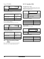
SX-D4160-EV (V) to SX-D4800-EV and SXD6200-EV(690V) to SX-D61K0-EV
Table 7
Cable specifications
Cable
Cable specification
Mains
Power cable suitable for fixed installation for the
voltage used.
Motor
Symmetrical three conductor cable with concentric protection (PE) wire or a four conductor cable
with compact low-impedance concentric shield
for the voltage used.
Control
Control cable with low-impedance shield,
screened.
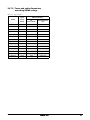
3.5
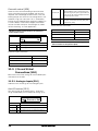
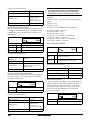
Stripping lengths
Fig. 19 indicates the recommended stripping lengths
for motor and mains cables.
Table 8
Stripping lengths for mains and motor cables
Mains cable
Model
L1 L2 L3 PE
Motor cable
a
(mm)
b
(mm)
a
(mm)
b
(mm)
c
(mm)
SX-D4090-EV
160
16
160
16
41
SX-D4110-EV to
SX-D4132-EV
SX-D6090-EV to
SX-D6160-EV
170
24
170
24
46
PE U V W
Mains
Motor
(06-F45-cables only)
Fig. 19 Stripping lengths for cables
Fig. 18 Connecting motor and mains cables
3.5.1
Dimension of cables and
fuses
VSD models SX-D4160-EV to SX-D4800-EV and SXD6200-EV to SX-D61K0-EV are supplied with Klockner Moeller K3x240/4 power clamps.
Please refer to the chapter Technical data, section
14.6, page 174.
For all type of wires to be connected the stripping
length should be 32 mm.
20
Installation
Omron SX inverter manual
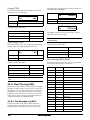
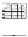
3.5.2
Table 9
Tightening torque for mains
and motor cables
Model SX-D4090-EV
Brake chopper
Mains/motor
95
150
Block, mm2
Cable diameter, mm2
16-95
35-95
120-150
Tightening torque, Nm
14
14
24
Table 10
Add the current for the motors in parallel.
Menu [225]
Motor Speed:
Set the average speed for the motors in
parallel.
Menu [227]
Motor Cos PHI:
Set the average Cos PHI value for the
motors in parallel.
Model SX-D4110-EV to SX-D4132-EV and SXD6090-EV to SX-D6160-EV
Brake chopper
Mains/motor
150
240
Block, mm2
Cable diameter, mm2
35-95 120-150
Tightening torque, Nm
3.6
Menu [224]
Motor Current:
14
24
35-70
95-240
14
24
Thermal protection on the
motor
Standard motors are normally fitted with an internal
fan. The cooling capacity of this built-in fan is dependent on the frequency of the motor. At low frequency,
the cooling capacity will be insufficient for nominal
loads. Please contact the motor supplier for the cooling characteristics of the motor at lower frequency.
WARNING: Depending on the cooling
characteristics of the motor, the application,
the speed and the load, it may be necessary
to use forced cooling on the motor.
Motor thermistors offer better thermal protection for
the motor. Depending on the type of motor thermistor
fitted, the optional PTC input may be used. The motor
thermistor gives a thermal protection independent of
the speed of the motor, thus of the speed of the motor
fan. See the functions, Motor I2t type [231] and Motor
I2t current [232].
3.7
Motors in parallel
It is possible to have motors in parallel as long as the
total current does not exceed the nominal value of the
VSD. The following has to be taken into account when
setting the motor data:
Menu [221]
Motor Voltage:
The motors in parallel must have the
same motor voltage.
Menu [222]
The motors in parallel must have the
Motor Frequency: same motor frequency.
Menu [223]
Motor Power:
Add the motor power values for the
motors in parallel.
Omron SX inverter manual
Installation
21
22
Installation
Omron SX inverter manual
4.
Getting Started
This chapter is a step by step guide that will show you
the quickest way to get the motor shaft turning. We
will show you two examples, remote control and local
control.
VSD
RFI-Filter
Mains
We assume that the VSD is mounted on a wall or in a
cabinet as in the chapter 2. page 11.
First there is general information of how to connect
mains, motor and control cables. The next section
describes how to use the function keys on the control
panel. The subsequent examples covering remote
control and local control describe how to program/set
the motor data and run the VSD and motor.
4.1
Metal EMC cable glands
Screened cables
Metal housing
Brake
resistor
(option)
Connect the mains and
motor cables
Metal connector housing
Dimension the mains and motor cables according to
local regulations. The cable must be able to carry the
VSD load current.
4.1.1
Output
coils
(option)
Mains cables
Metal cable gland
Motor
Mains
Fig. 20 Connection of mains and motor cables
7. Connect the mains cables as in Fig. 20. The VSD
has, as standard, a built-in RFI mains filter that
complies with category C3 which suits the Second
Environment standard.
4.1.2
Motor cables
8. Connect the motor cables as in Fig. 20. To comply
with the EMC Directive you have to use screened
cables and the motor cable screen has to be connected on both sides: to the housing of the motor
and the housing of the VSD.
Omron SX inverter manual
Getting Started
23
Table 11
Mains and motor connection
L1,L2,L3
PE
Mains supply, 3 -phase
Safety earth
U, V, W
Motor earth
Motor output, 3-phase
To comply with the EMC standard, use screened control cables with plaited flexible wire up to 1.5 mm2 or
solid wire up to 2.5 mm2.
9. Connect a reference value between terminals 7
(Common) and 2 (AnIn 1) as in Fig. 22.
WARNING: In order to work safely the mains
earth must be connected to PE and the motor
earth to
.
10.Connect an external start button between terminal
11 (+24 VDC) and 9 (DigIn2, RUNR) as in Fig. 22.
X1
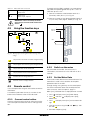
4.2
Using the function keys
Reference
4-20 mA
1
+
2
3
0V
100
200
4
300
5
6
7
8
210
Start
220
9
10
11
12
13
14
15
16
17
18
19
20
21
22
221
X2
31
32
33
Fig. 21 Example of menu navigation when entering motor
voltage
41
42
43
X3
51
52
step to lower menu level or confirm changed setting
step to higher menu level or ignore changed setting
Fig. 22 Wiring
step to next menu on the same level
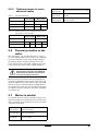
4.3.2
step to previous menu on the same level
Close the door to the VSD. Once the mains is
switched on, the internal fan in the VSD will run for 5
seconds.
increase value or change selection
4.3.3
Remote control
In this example external signals are used to control the
VSD/motor.
A standard 4-pole motor for 400 V, an external start
button and a reference value will also be used.
4.3.1
Set the Motor Data
Enter correct motor data for the connected motor. The
motor data is used in the calculation of complete
operational data in the VSD.
decrease value or change selection
4.3
Switch on the mains
Change settings using the keys on the control panel.
For further information about the control panel and
menu structure, see the chapter 9. page 47.
Menu [100], Preferred View is displayed when started.
1. Press
to display menu [200], Main Setup.
2. Press
and then
Motor Data.
Connect control cables
Here you will make up the minimum wiring for starting.
In this example the motor/VSD will run with right rotation.
3. Press
age.
to display menu [220],
to display menu [221] and set motor volt-
4. Change the value using the
firm with
.
and
keys. Con-
5. Set motor frequency [222].
24
Getting Started
Omron SX inverter manual
7. Select Keyboard using the key
confirm.
6. Set motor power [223].
7. Set motor current [224].
and press
8. Press
to get to previous menu level and then
to display menu [220], Motor Data.
8. Set motor speed [225].
9. Set power factor (cos ) [227].
10.Select supply voltage level used [21B]
4.4.3
11.[229] Motor ID run: Choose Short, confirm with
and give start command .
Enter correct motor data for the connected motor.
9. Press
The VSD will now measure some motor parameters.
The motor makes some beeping sounds but the shaft
does not rotate. When the ID run is finished after
about one minute ("Test Run OK!" is displayed),
press
to continue.
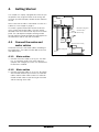
12.Use AnIn1 as input for the reference value. The
default range is 4-20 mA. If you need a 0-10 V reference value, change switch (S1) on control board
and set [512] Anln 1 Set-up to 0-10V.
13.Switch off power supply.
14.Connect digital and analogue inputs/outputs as in
Fig. 22.
Set the Motor Data
to display menu [221].
10.Change the value using the
firm with
.
11.Press
and
keys. Con-
to display menu [222].
12.Repeat step 9 and 10 until all motor data is
entered.
13.Press
twice and then
Preferred View.
4.4.4
to display menu [100],
Enter a Reference Value
Enter a reference value.
15.Ready!
14.Press
16.Switch on power supply.
15.Press
to display menu [310], Set/View reference value.
4.3.4
to
Run the VSD
until menu [300], Process is displayed.
Now the installation is finished, and you can press the
external start button to start the motor.
16.Use the
and
keys to enter, for example,
300 rpm. We select a low value to check the rotation direction without damaging the application.
When the motor is running the main connections are
OK.
4.4.5
4.4
Press the
forward.
Local control
Run the VSD
key on the control panel to run the motor
If the motor is running the main connections are OK.
Manual control via the control panel can be used to
carry out a test run.
Use a 400 V motor and the control panel.
4.4.1
Switch on the mains
Close the door to the VSD. Once the mains is
switched on, the VSD is started and the internal fan
will run for 5 seconds.
4.4.2
Select manual control
Menu [100], Preferred View is displayed when started.
1. Press
to display menu [200], Main Setup.
2. Press
to display menu [210], Operation.
3. Press
to display menu [211], Language.
4. Press
trol.
to display menu [214], Reference Con-
5. Select Keyboard using the key
confirm.
6. Press
and press
to
to get to menu [215], Run/Stop Control.
Omron SX inverter manual
Getting Started
25
26
Getting Started
Omron SX inverter manual
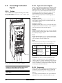
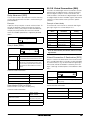
5.
Control Connections
5.1
Control board
WARNING: Always switch off the mains
voltage and wait at least 5 minutes to allow
the DC capacitors to discharge before
connecting the control signals or changing
position of any switches. If the option External supply is
used, switch of the mains to the option. This is done to
prevent damage on the control board.
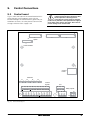
Fig. 23 shows the layout of the control board which is
where the parts most important to the user are
located. Although the control board is galvanically isolated from the mains, for safety reasons do not make
changes while the mains supply is on!
X5
X6
1
X4
X7
2
3
Option
C
X8
Communication
Control
Panel
Switches
I
S1 U
I
S2
U
S3
I
U
I
S4 U
Control
signals
12
13 14 15 16 17 18
21 22
19 20
R02
41 42 43
Relay outputs
DI4 DI5 DI6 DI7 DO1 DO2 DI8
AO1 AO2
X1 1
2
3
+10V AI1 AI2
4
5
AI3
AI4
6
-10V
7
8
9
10 11
DI1 DI2 DI3 +24V
NC
C
NO
X2 31 32 33
NC
C
R01
NO
51 52
X3
NO
C
R03
Fig. 23 Control board layout
Omron SX inverter manual
Control Connections
27
5.2
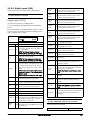
Terminal connections
Table 12
The terminal strip for connecting the control signals is
accessible after opening the front panel.
The table describes the default functions for the signals. The inputs and outputs are programmable for
other functions as described in chapter 11. page 59.
For signal specifications refer to chapter 14. page 169.
NOTE: The maximum total combined current for outputs
11, 20 and 21 is 100mA.
Table 12
Terminal
Name
41
N/C 2
42
COM 2
43
N/O 2
51
COM 3
52
N/O 3
Function (Default)
Relay 2 output
Run, active when the VSD is
started.
Relay 3 output
Off
NOTE: N/C is opened when the relay is active and N/O is
closed when the relay is active.
Control signals
Terminal
Control signals
Name
Function (Default)
Outputs
1
+10 V
+10 VDC supply voltage
6
-10 V
-10 VDC supply voltage
7
Common
Signal ground
11
+24 V
+24 VDC supply voltage
12
Common
Signal ground
15
Common
Signal ground
8
DigIn 1
RunL (reverse)
9
DigIn 2
RunR (forward)
10
DigIn 3
Off
16
DigIn 4
Off
17
DigIn 5
Off
18
DigIn 6
Off
19
DigIn 7
Off
22
DigIn 8
RESET
5.3
Inputs configuration
with the switches
The switches S1 to S4 are used to set the input configuration for the 4 analogue inputs AnIn1, AnIn2,
AnIn3 and AnIn4 as described in table 13. See Fig. 23
for the location of the switches.
Table 13
Switch settings
Input
Digital inputs
Voltage
AnIn1
Current (default)
Voltage
AnIn2
Current (default)
Voltage
AnIn3
Current (default)
Digital outputs
20
DigOut 1
Ready
21
DigOut 2
Brake
Voltage
AnIn4
Current (default)
Analogue inputs
2
AnIn 1
Process Ref
3
AnIn 2
Off
4
AnIn 3
Off
5
AnIn 4
Off
AnOut1
Min speed to max speed
14
AnOut2
0 to max torque
Switch
S1
I
U
S1
I
U
S2
I
U
S2
I
U
S3
I
U
S3
I
U
S4
I
U
S4
I
U
NOTE: Scaling and offset of AnIn1 - AnIn4 can be
configured using the software. See menus [512], [515],
[518] and [51B] in section 11.5, page 119.
NOTE: the 2 analogue outputs AnOut 1 and AnOut 2 can
be configured using the software. See menu [530]
section 11.5.3, page 128
Analogue outputs
13
Signal type
Relay outputs
31
N/C 1
32
COM 1
33
N/O 1
28
Relay 1 output
Trip, active when the VSD is in a
TRIP condition.
Control Connections
Omron SX inverter manual
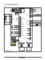
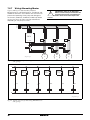
5.4
Connection example
Fig. 24 gives an overall view of a VSD connection
example.
L1
L2
L3
PE
U
V
W
RFIfilter
Alternative for
potentiometer control**
1
2
3
0 - 10 V
4 4 - 20 mA
5
6
7
Motor
DC+
Optional
1
2
3
4
5
6
7
8
9
10
11
15
16
17
18
19
22
+10 VDC
R
DC -
AnIn 1: Reference
AnIn 2
AnIn 3
Common
AnIn 4
AnOut 1
-10 VDC
AnOut 2
Common
DigOut 1
DigIn 1:RunL*
DigOut 2
12
13
21
14
20
21
DigIn 2:RunR*
DigIn3
+24 VDC
Relay 1
Common
DigIn 4
DigIn 5
31
32
33
41
DigIn 6
Relay 2
DigIn 7
DigIn 8:Reset*
Relay 3
42
43
51
52
Other options
Fieldbus option
or PC
* Default setting
** The switch S1 is set to U
Option board
NG_06-F27
Fig. 24 Connection example
Omron SX inverter manual
Control Connections
29
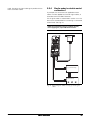
5.5
5.5.1
Connecting the Control
Signals
Cables
The standard control signal connections are suitable
for stranded flexible wire up to 1.5 mm2 and for solid
wire up to 2.5 mm2.
.
5.5.2
Types of control signals
Always make a distinction between the different types
of signals. Because the different types of signals can
adversely affect each other, use a separate cable for
each type. This is often more practical because, for
example, the cable from a pressure sensor may be
connected directly to the variable speed drive.
We can distinguish between the following types of
control signals:
Analogue inputs
Voltage or current signals, (0-10 V, 0/4-20 mA) normally used as control signals for speed, torque and
PID feedback signals.
Analogue outputs
Voltage or current signals, (0-10 V, 0/4-20 mA) which
change slowly or only occasionally in value. In general,
these are control or measurement signals.
Digital
Voltage or current signals (0-10 V, 0-24 V, 0/4-20 mA)
which can have only two values (high or low) and only
occasionally change in value.
Data
Usually voltage signals (0-5 V, 0-10 V) which change
rapidly and at a high frequency, generally data signals
such as RS232, RS485, Profibus, etc.
Relay
Relay contacts (0-250 VAC) can switch highly inductive loads (auxiliary relay, lamp, valve, brake, etc.).
Signal
type
Control signals
Maximum wire size
Analogue Rigid cable:
0.14-2.5 mm2
Digital
Flexible cable:
0.14-1.5 mm2
Data
Cable with ferrule:
Relay
0.25-1.5 mm2
Tightening
torque
Cable type
Screened
Screened
0.5 Nm
Screened
Not screened
Example:
The relay output from a variable speed drive which
controls an auxiliary relay can, at the moment of
switching, form a source of interference (emission) for
a measurement signal from, for example, a pressure
sensor. Therefore it is advised to separate wiring and
screening to reduce disturbances.
Fig. 25 Connecting the control signals SX-D4090
NOTE: The screening of control signal cables is
necessary to comply with the immunity levels given in
the EMC Directive (it reduces the noise level).
NOTE: Control cables must be separated from motor and
mains cables.
5.5.3
Screening
For all signal cables the best results are obtained if the
screening is connected to both ends: the VSD side
and the at the source (e.g. PLC, or computer). See
Fig. 26.
It is strongly recommended that the signal cables be
allowed to cross mains and motor cables at a 90
30
Control Connections
Omron SX inverter manual
angle. Do not let the signal cable go in parallel with the
mains and motor cable.
5.5.4
Single-ended or double-ended
connection?
In principle, the same measures applied to motor
cables must be applied to all control signal cables, in
accordance with the EMC-Directives.
For all signal cables as mentioned in section 5.5.2 the
best results are obtained if the screening is connected
to both ends. See Fig. 26.
NOTE: Each installation must be examined carefully
before applying the proper EMC measurements.
Control board
Pressure
sensor
(example)
External control
(e.g. in metal housing)
Control consol
Fig. 26 Electro Magnetic (EM) screening of control signal
cables.
Omron SX inverter manual
Control Connections
31
5.5.5
Current signals ((0)4-20 mA)
A current signal like (0)4-20 mA is less sensitive to disturbances than a 0-10 V signal, because it is connected to an input which has a lower impedance (250
) than a voltage signal (20 k). It is therefore strongly
advised to use current control signals if the cables are
longer than a few metres.
5.5.6
Twisted cables
Analogue and digital signals are less sensitive to interference if the cables carrying them are “twisted”. This
is certainly to be recommended if screening cannot be
used. By twisting the wires the exposed areas are
minimised. This means that in the current circuit for
any possible High Frequency (HF) interference fields,
no voltage can be induced. For a PLC it is therefore
important that the return wire remains in proximity to
the signal wire. It is important that the pair of wires is
fully twisted over 360°.
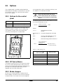
5.6
Connecting options
The option cards are connected by the optional connectors X4 or X5 on the control board see Fig. 23,
page 27 and mounted above the control board. The
inputs and outputs of the option cards are connected
in the same way as other control signals.
32
Control Connections
Omron SX inverter manual
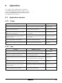
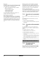
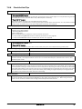
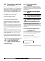
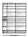
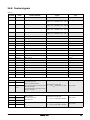
6.
Applications
This chapter contains tables giving an overview of
many different applications/duties in which it is suitable to use variable speed drives from OMRON. Further
on you will find application examples of the most common applications and solutions.
6.1
6.1.1
s
Application overview
Pumps
Challenge
OMRON SX-V solution
Menu
High start currents require larger fuses and cables. Torque control reduces start current. Same fuses
331–336, 351
Cause stress on equipment and higher energy cost. can be used as those required for the motor.
Dry-running, cavitation and overheating damage
the pump and cause downtime.
Pump Curve Protection detects deviation. Sends
411–419, 41C1– 41C9
warning or activates safety stop.
Sludge sticks to impeller when pump has been run- Automatic pump rinsing function: pump is set to
ning at low speed or been stationary for a while.
run at full speed at certain intervals, then return 362–368, 560, 640
Reduces the pump’s efficiency.
to normal speed.
Motor runs at same speed despite varying
demands in pressure/flow. Energy is lost and
equipment stressed.
PID continuously adapts pressure/flow to the
level required. Sleep function activated when
none is needed.
320, 380, 342, 354
Process inefficiency due to e.g. a blocked pipe, a
valve not fully opened or a worn impeller.
Pump Curve Protection detects deviation. Warning is sent or safety stop activated.
411–419, 41C1–41C9
Water hammer damages the pump when stopped. Smooth linear stops protect the equipment. Elimi331–336
Mechanical stress on pipes, valves, gaskets, seals. nates need for costly motorized valves.
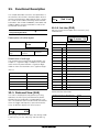
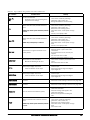
6.1.2
Fans
Challenge
OMRON SX-V solution
Menu
High start currents require larger fuses and cables. Torque control reduces start current. Same fuses
331–336, 351
Cause stress on equipment and higher energy cost. can be used as those required for the motor.
Starting a fan rotating in the wrong direction can be Fan is started at low speed to ensure correct
critical, e.g. a tunnel fan in event of a fire.
direction and proper function.
219, 341
Draft causes turned off fan to rotate the wrong way.
Motor is gradually slowed to complete stop before
Starting causes high current peaks and mechanical
219, 33A, 335
starting. Avoids blown fuses and breakdown.
stress.
Regulating pressure/flow with dampers causes
high energy consumption and equipment wear.
Automatic regulation of pressure/flow with motor
321, 354
speed gives more exact control.
Motor runs at same speed despite varying
demands in pressure/flow. Energy is lost and
equipment stressed.
PID continuously adapts to the level required.
320, 380, 342, 354
Sleep function is activated when none is needed.
Process inefficiency due to e.g. a blocked filter, a
damper not fully opened or a worn belt.
Load Curve Protection detects deviation. Warning
411–419, 41C1–41C9
is sent or safety stop activated.
Omron SX inverter manual
Applications
33
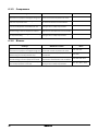
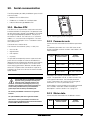
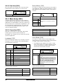
6.1.3
Compressors
Challenge
OMRON SX-V solution
Menu
High start currents require larger fuses and cables. Torque control reduces start current. Same fuses
331– 336, 351
Cause stress on equipment and higher energy cost. can be used as those required for the motor.
Compressor is damaged when cooling media
enters the compressor screw.
Overload situation is quickly detected and safety
411–41A
stop can be activated to avoid breakdown.
Pressure is higher than needed, causing leaks,
stress on the equipment and excessive air use.
Load Curve Protection function detects deviation.
411–419, 41C1–41C9
Warning is sent or safety stop activated.
Motor runs at same speed when no air is compressed. Energy is lost and equipment stressed.
PID continuously adapts to the level required.
Sleep function activated when none is needed.
Process inefficiency and energy wasted due to e.g. Load Curve Protection quickly detects deviation.
the compressor idling.
Warning is sent or safety stop activated.
6.1.4
320, 380, 342, 354
411–419, 41C1–41C9
Blowers
Challenge
OMRON SX-V solution
Menu
High start currents require larger fuses and cables. Torque control reduces start current. Same fuses
331–336, 351
Cause stress on equipment and higher energy cost. can be used as those required for the motor.
Difficult to compensate for pressure fluctuations.
Wasted energy and risk of production stop.
PID function continuously adapts pressure to the
320, 380
level required.
Motor runs at same speed despite varying
demands. Energy is lost and equipment stressed.
PID continuously adapts air flow to level required.
320, 380, 342, 354
Sleep function activated when none is needed.
Process inefficiency due to e.g. a broken damper, a Load Curve Protection quickly detects deviation.
valve not fully opened or a worn belt.
Warning is sent or safety stop activated.
34
Applications
411–419, 41C1–41C9
Omron SX inverter manual
7.
Main Features
This chapter contains descriptions of the main features of the VSD.
7.1
Parameter Set A
Run/Stop
Torques
Controllers
Limits/Prot.
-
Parameter sets
Parameter sets are used if an application requires different settings for different modes. For example, a
machine can be used for producing different products
and thus requires two or more maximum speeds and
acceleration/deceleration times. With the four parameter sets different control options can be configured
with respect to quickly changing the behaviour of the
VSD. It is possible to adapt the VSD online to altered
machine behaviour. This is based on the fact that at
any desired moment any one of the four parameter
sets can be activated during Run or Stop, via the digital inputs or the control panel and menu [241].
Set B
Set C
Set D
-Max Alarm
11 +24 V
10 Set Ctrl1
16 Set Ctrl2
{
(NG06-F03_1)
Each parameter set can be selected externally via a
digital input. Parameter sets can be changed during
operation and stored in the control panel.
NOTE: The only data not included in the parameter set is
Motor data 1-4, (entered separately), language,
communication settings, selected set, local remote, and
keyboard locked.
Define parameter sets
When using parameter sets you first decide how to
select different parameter sets. The parameter sets
can be selected via the control panel, via digital inputs
or via serial communication. All digital inputs and virtual inputs can be configured to select parameter set.
The function of the digital inputs is defined in the menu
[520].
Fig. 27 shows the way the parameter sets are activated via any digital input configured to Set Ctrl 1 or
Set Ctrl 2.
Fig. 27 Selecting the parameter sets
Select and copy parameter set
The parameter set selection is done in menu [241],
Select Set. First select the main set in menu [241],
normally A. Adjust all settings for the application. Usually most parameters are common and therefore it
saves a lot of work by copying set A>B in menu [242].
When parameter set A is copied to set B you only
change the parameters in the set that need to be
changed. Repeat for C and D if used.
With menu [242], Copy Set, it is easy to copy the
complete contents of a single parameter set to
another parameter set. If, for example, the parameter
sets are selected via digital inputs, DigIn 3 is set to Set
Ctrl 1 in menu [523] and DigIn 4 is set to Set Ctrl 2 in
menu [524], they are activated as in Table 14.
Activate the parameter changes via digital input by
setting menu [241], Select Set to DigIn.
Table 14
Parameter set
Parameter set
Set Ctrl 1
Set Ctrl 2
A
0
0
B
1
0
C
0
1
D
1
1
NOTE: The selection via the digital inputs is immediately
activated. The new parameter settings will be activated
on-line, also during Run.
NOTE: The default parameter set is parameter set A.
Omron SX inverter manual
Main Features
35
Examples
Bottling machine with 3 different products
Different parameter sets can be used to easily change
the setup of a VSD to adapt quickly to different application requirements. For example when
Use 3 parameter sets for 3 different Jog reference
speeds when the machine needs to be set up. The 4th
parameter set can be used for “normal” remote control when the machine is running at full production.
• a process needs optimized settings in different
stages of the process, to
- increase the process quality
- increase control accuracy
- lower maintenance costs
- increase operator safety
Manual - automatic control
If in an application something is filled up manually and
then the level is automatically controlled using PID regulation, this is solved using one parameter set for the
manual control and one for the automatic control.
With these settings a large number of options are
available. Some ideas are given here:
7.1.1
Multi frequency selection
Within a single parameter set the 7 preset references
can be selected via the digital inputs. In combination
with the parameter sets, 28 preset references can be
selected using all 4 digital inputs: DigIn1, 2 and 3 for
selecting preset reference within one parameter set
and DigIn 4 and DigIn 5 for selecting the parameter
sets.
One motor and one parameter
set
This is the most common application for pumps and
fans.
Once default motor M1 and parameter set A have
been selected:
1. Enter the settings for motor data.
2. Enter the settings for other parameters e.g. inputs
and outputs
7.1.2
One motor and two parameter
sets
This application is useful if you for example have a
machine running at two different speeds for different
products.
Once default motor M1 is selected:
1. Select parameter set A in menu [241].
2. Enter motor data in menu [220].
3. Enter the settings for other parameters e.g. inputs
and outputs.
4. If there are only minor differences between the settings in the parameter sets, you can copy parameter set A to parameter set B, menu [242].
5. Enter the settings for parameters e.g. inputs and
outputs.
Note: Do not change motor data in parameter set B.
7.1.3
Two motors and two
parameter sets
This is useful if you have a machine with two motors
that can not run at the same time, such as a cable
winding machine that lifts up the reel with one motor
and then turns the wheel with the other motor.
36
Main Features
Omron SX inverter manual
One motor must stop before changing to an other
motor.
1. Select parameter set A in menu [241].
2. Select motor M1 in menu [212].
3. Enter motor data and settings for other parameters
e.g. inputs and outputs.
4. Select parameter set B in menu [241].
5. Select M2 in menu [212].
6. Enter motor data and settings for other parameters
e.g. inputs and outputs.
7.1.4
Example
The VSD is able to select fixed speeds via the control
of digital inputs. This can be used for situations where
the required motor speed needs to be adapted to
fixed values, according to certain process conditions.
Up to 7 preset references can be set for each parameter set, which can be selected via all digital inputs that
are set to Preset Ctrl1, Preset Ctrl2 or Preset Ctrl3.
The amount digital inputs used that are set to Preset
Ctrl determines the number of Preset References
available; using 1 input gives 2 speeds, using 2 inputs
gives 4 speeds and using 3 inputs gives 8 speeds.
The use of four fixed speeds, at 50 / 100 / 300 / 800
rpm, requires the following settings:
• Set DigIn 5 as first selection input; set [525] to Preset Ctrl1.
• Set DigIn 6 as second selection input; set [526] to
Preset Ctrl2.
• Set menu [341], Min Speed to 50 rpm.
• Set menu [362], Preset Ref 1 to 100 rpm.
• Set menu [363], Preset Ref 2 to 300 rpm.
The motor is protected by an internal protection for
thermal overload. When this protection is activated,
the VSD should wait until the motor is cooled down
enough before resuming normal operation. When this
problem occurs three times in a short period of time,
external assistance is required.
• Insert maximum number of restarts; set menu [251]
to 3.
I2t
• Activate Motor
to be automatically reset; set
menu [25A] to 300 s.
• Set relay 1, menu [551] to AutoRst Trip; a signal will
be available when the maximum number of restarts
is reached and the VSD stays in fault condition.
• The reset input must be constantly activated.
Reference priority
The active speed reference signal can be programmed
from several sources and functions. The table below
shows the priority of the different functions with
regards to the speed reference.
Table 15 Reference priority
Preset
Reference
Motor Pot
With these settings, the VSD switched on and a RUN
command given, the speed will be:
• 50 rpm, when both DigIn 5 and DigIn 6 are low.
• 300 rpm, when DigIn 5 is low and DigIn 6 is high.
• 800 rpm, when both DigIn 5 and DigIn 6 are high.
7.2
Remote control functions
Operation of the Run/Stop/Enable/Reset functions
As default, all the run/stop/reset related commands
are programmed for remote operation via the inputs
on the terminal strip (terminals 1-22) on the control
board. With the function Run/Stp Ctrl [215] and Reset
Control [216], this can be selected for keyboard or
serial communication control.
NOTE: The examples in this paragraph do not cover all
possibilities. Only the most relevant combinations are
given. The starting point is always the default setting
(factory) of the VSD.
Ref. Signal
On/Off
On/Off
On/Off
Option cards
On
On/Off
On/Off
Jog Ref
Off
On
On/Off
Preset Ref
Off
Off
On
Motor pot commands
Omron SX inverter manual
• Set menu [364], Preset Ref 3 to 800 rpm.
• 100 rpm, when DigIn 5 is high and DigIn 6 is low.
The following settings should be applied:
Jog
Mode
Preset references
Example
Autoreset at trip
For several non-critical application-related failure conditions, it is possible to automatically generate a reset
command to overcome the fault condition. The selection can be made in menu [250]. In this menu the maximum number of automatically generated restarts
allowed can be set, see menu [251], after this the VSD
will stay in fault condition because external assistance
is required.
7.1.5
7.1.6
Main Features
37
Default settings of the Run/Stop/
Enable/Reset functions
STOP
The default settings are shown in Fig. 28. In this example the VSD is started and stopped with DigIn 2 and a
reset after trip can be given with DigIn 8.
(STOP=DECEL)
OUTPUT
SPEED
t
X1
1
2
3
4
5
6
7
8
RunR
9
Reset
+24 V
10
11
12
13
14
15
16
17
ENABLE
18
19
OUTPUT
SPEED
20
21
22
t
(06-F104_NG)
(or if Spinstart is selected)
X
Fig. 28 Default setting Run/Reset commands
Fig. 29 Functionality of the Stop and Enable input
The inputs are default set for level-control. The rotation
is determined by the setting of the digital inputs.
Enable and Stop functions
Both functions can be used separately or simultaneously. The choice of which function is to be used
depends on the application and the control mode of
the inputs (Level/Edge [21A]).
NOTE: In Edge mode, at least one digital input must be
programmed to “stop”, because the Run commands are
otherwise only able to start the VSD.
Enable
Input must be active (HI) to allow any Run signal. If the
input is made LOW, the output of the VSD is immediately disabled and the motor will coast.
!
CAUTION: If the Enable function is not
programmed to a digital input, it is considered
to be active internally.
Reset and Autoreset operation
If the VSD is in Stop Mode due to a trip condition, the
VSD can be remotely reset by a pulse (“low” to “high”
transition) on the Reset input, default on DigIn 8.
Depending on the selected control method, a restart
takes place as follows:
Level-control
If the Run inputs remain in their position the VSD will
start immediately after the Reset command is given.
Edge-control
After the Reset command is given a new Run command must be applied to start the VSD again.
Autoreset is enabled if the Reset input is continuously
active. The Autoreset functions are programmed in
menu Autoreset [250].
NOTE: If the control commands are programmed for
Keyboard control or Com, Autoreset is not possible.
Run Inputs Level-controlled.
Stop
If the input is low then the VSD will stop according to
the selected stop mode set in menu [33B] Stop Mode.
Fig. 29 shows the function of the Enable and the Stop
input and the Stop Mode=Decel [33B].
The inputs are set as default for level-control. This
means that an input is activated by making the input
continuously “High”. This method is commonly used if,
for example, PLCs are used to operate the VSD.
To run the input must be high.
NOTE: Stop Mode=Coast [33B] will give the same
behaviour as the Enable input.
38
!
CAUTION: Level-controlled inputs DO NOT
comply with the Machine Directive, if the inputs
are directly used to start and stop the machine.
The examples given in this and the following paragraphs follow the input selection shown in Fig. 30.
Main Features
Omron SX inverter manual
X1
1
2
3
4
Stop
5
6
7
RunL
8
RunR
9
Enable
Reset
+24 V
10
11
See Fig. 30. The Enable and Stop input must be active
continuously in order to accept any run-right or run-left
command. The last edge (RunR or RunL) is valid. Fig.
32 gives an example of a possible sequence.
12
13
14
15
INPUTS
16
ENABLE
17
18
STOP
19
20
21
RUN R
22
RUN L
Fig. 30 Example of wiring for Run/Stop/Enable/Reset inputs
The Enable input must be continuously active in order
to accept any run-right or run-left command. If both
RunR and RunL inputs are active, then the VSD stops
according to the selected Stop Mode. Fig. 31 gives an
example of a possible sequence.
OUTPUT
STATUS
Right rotation
Left rotation
INPUTS
Standstill
(06-F94new_1)
ENABLE
Fig. 32 Input and output status for edge-control
STOP
RUN R
7.3
RUN L
To get the optimum performance out of your VSD/
motor combination, the VSD must measure the electrical parameters (resistance of stator winding, etc.) of
the connected motor. See menu [229], Motor ID-Run.
OUTPUT
STATUS
7.4
Right rotation
Left rotation
Standstill
(06-F103new_1)
Fig. 31 Input and output status for level-control
Run Inputs Edge-controlled
Menu [21A] Start signal Level/Edge must be set to
Edge to activate edge control. This means that an
input is activated by a “low” to “high” transition or vice
versa.
NOTE: Edge-controlled inputs comply with the Machine
Directive (see chapter EMC and Machine Directive), if
the inputs are directly used for starting and stopping the
machine.
Omron SX inverter manual
Performing an
Identification Run
Using the Control Panel
Memory
Data can be copied from the VSD to the memory in
the control panel and vice versa. To copy all data
(including parameter set A-D and motor data) from the
VSD to the control panel, select Copy to CP[244],
Copy to CP.
To copy data from the control panel to the VSD, enter
the menu [245], Load from CP and select what you
want to copy.
The memory in the control panel is useful in applications with VSDs without a control panel and in applications where several variable speed drives have the
same setup. It can also be used for temporary storage
of settings. Use a control panel to upload the settings
Main Features
39
from one VSD and then move the control panel to
another VSD and download the settings.
NOTE: Load from and copy to the VSD is only possible
when the VSD is in stop mode.
The max and min alarm can be set for a trip condition.
The pre-alarms act as a warning condition. All the
alarms can be monitored on the digital or relay outputs.
The autoset function automatically sets the 4 alarm
levels whilst running: maximum alarm, maximum prealarm, minimum alarm and minimum pre-alarm.
Fig. 34 gives an example of the monitor functions for
constant torque applications.
VSD
Fig. 33 Copy and load parameters between VSD and control
panel
7.5
Load Monitor and Process
Protection [400]
7.5.1 Load Monitor [410]
The monitor functions enable the VSD to be used as a
load monitor. Load monitors are used to protect
machines and processes against mechanical overload
and underload, such as a conveyer belt or screw conveyer jamming, belt failure on a fan or a pump dry running. The load is measured in the VSD by the
calculated motor shaft torque. There is an overload
alarm (Max Alarm and Max Pre-Alarm) and an underload alarm (Min Alarm and Min Pre-Alarm).
The Basic Monitor type uses fixed levels for overload
and underload (pre-)alarms over the whole speed
range. This function can be used in constant load
applications where the torque is not dependent on the
speed, e.g. conveyor belt, displacement pump, screw
pump, etc.
For applications with a torque that is dependent on the
speed, the Load Curve monitor type is preferred. By
measuring the actual load curve of the process, characteristically over the range of minimum speed to
maximum speed, an accurate protection at any speed
can be established.
40
Main Features
Omron SX inverter manual
Fig. 34
Omron SX inverter manual
Main Features
41
100%
Default: TNOM or
Autoset: TMOMENTARY
Min PreAlarm
Min Alarm
Max PreAlarm
Max Alarm
[4191] MinAlarmMar (15%)
[4181] MinPreAlMar (10%)
[41B]
[4171] MaxPreAlMar (10%)
[4161] MaxAlarmMar (15%)
Torque [%]
[414] Start Delay (0.2s)
[4172] MaxPreAlDel (0.1s)
[4162] MaxAlarmDel (0.1s)
[411] Alarm Select=Max or Max0Min
[413] Ramp Alarm=On
Ramp-up phase
Must be elapsed before first (pre)alarm
[4192] MinAlarmDel (0.1s)
[4182] MinPreAlDel (0.1s)
[411] Alarm Select=Max or Max0Min
[413] Ramp Alarm=On or Off
Stationary phase
Must be <t (or t´) otherwise no (pre)alar
[4172] MaxPreAlDel (0.1s)
[4162] MaxAlarmDel (0.1s)
[411] Alarm Select=Max or Max0Min
[413] Ramp Alarm=On or Off
Stationary phase
t [s]
[4192] MinAlarmDel (0.1s)
[4182] MinPreAlDel (0.1s)
Must be <t (or t´) otherwise no (pre)alar
[411] Alarm Select=Max or Max0Min
[413] Ramp Alarm=On
Ramp-down phase
7.6
Pump sequencer function
7.6.1
All additional pumps can be activated via a VSD, soft
starter, Y/ or D.O.L. switches.
Introduction
PM
A maximum of 4 pumps can be controlled with the
standard SX-V variable speed drive.
If I/O Board options are installed, a maximum of 7
pumps can be controlled. The I/O Board can also be
used as a general extended I/O.
P2
P3
P4
P5
P6
SX-V R:SlavePump1
MASTER
Set
PRESSURE
Feedback
PRESSURE
R:SlavePump2
AnIn
PI D
AnIn
The Pump Control function is used to control a
number of drives (pumps, fans, etc., with a maximum
of 3 additional drives per I/O-board connected) of
which one is always driven by the SX-V. Other names
for this kind of controllers are 'Cascade controller' or
'Hydrophore controller'.
R:SlavePump3
R:SlavePump4
R:SlavePump5
R:SlavePump6
Pr essur e
4
Depending on the flow, pressure or temperature, additional pumps can be activated via the appropriate signals by the output relays of the SX-V and/or the I/O
Board. The system is developed in such a way that
one SX-V will be the master of the system.
Select relay on the control board or on an option
board. The relays are set to functions for controlling
pumps. In the pictures in this section, the relays are
named R:Function, e.g. R:SlavePump1, which means
a relay on the control board or on an option board set
to function SlavePump1.
P1
3
2
1
Power
Flow
(50-PC-2_1)
Fig. 36 Pressure control with pump control option
Pumps in parallel will operate as a flow controller, See
Fig. 35.
Pumps in series will operate as a pressure controller
see Fig. 36. The basic control principle is shown in Fig.
37.
PM
P1
P2
P3
P4
P5
P6
NOTE: Read this instruction manual carefully before
commencing installation, connecting or working with
the variable speed drive with Pump Control.
SX-V
R:SlavePump1
MASTER
R:SlavePump2
Set FLOW
AnIn
Feedback
FLOW
PID
AnIn
R:SlavePump3
R:SlavePump4
R:SlavePump5
R:SlavePump6
FREQUENCY (master pump P)
Add pump
Pr essur e
Stop pump
P=on
P1=on P2=on P3=on P4=on P5=on P6=on
Power
1
2
3
4
FLOW /
PRESSURE
Flow
FLOW /
PRESSURE
(50-PC-1_1)
Fig. 35 Flow control with pump control option
TIM E
(50-PC-3_1)
Fig. 37 Basic Control principle
42
Main Features
Omron SX inverter manual
7.6.2
Fixed MASTER
This is the default setting of the Pump Control. The
SX-V controls the Master pump which is always running. The relay outputs start and stop the other pumps
P1 to P6, depending on flow/pressure. In this configuration a maximum of 7 pumps can be controlled, see
Fig. 38. To equalize the lifetime of the additional
pumps it is possible to select the pumps depending
on the run time history of each pump.
SX-V
MASTER
R: SlavePump6
R: SlavePump5
R: SlavePump4
R: SlavePump3
R: SlavePump2
R: SlavePump1
R: MasterPump6
R: MasterPump5
R: MasterPump4
R: MasterPump3
R: MasterPump2
R: MasterPump1
P1
SX-V
MASTER
P2
P3
P4
P5
P6
See menu:
[393] to [396]
[553] to [55C]
R:SlavePump6
R:SlavePump5
R:SlavePump4
R:SlavePump3
R:SlavePump2
R:SlavePump1
Fig. 39 Alternating MASTER Control
(NG_50-PC-4_1)
PM
P1
P2
P3
P4
P5
P6
See menu:
[393] Select Drive
[39H] to [39N] Run Time 1 - 6, Pump
[554] to [55C] Relays
7.6.4
Fig. 38 Fixed MASTER control
NOTE: The pumps MAY have different powers, however
the MASTER pump MUST always be the largest.
7.6.3
Alternating MASTER
With this function the Master pump is not fixed to the
SX-V all the time. After the VSD is powered up or
started again after a stop or sleep mode the Master
pump is selected via the relay set to function Master
Pump. section 7.6.7 on page 49 shows a detailed wiring diagram with 3 pumps. The purpose of this function is that all pumps are used equally, so the lifetime
of all pumps, including the Master pump, will be equalized. Maximum 6 pumps can be controlled with this
function.
Omron SX inverter manual
NOTE: The pumps MUST have all the same power.
Feedback 'Status' input
In this example the additional pumps are controlled by
an other kind of drive (e.g. soft starter, frequency
inverter, etc.). The digital inputs on the I/O Board can
be programmed as a "Error" input for each pump. If a
drive fails the digital input will monitor this and the
PUMP CONTROL option will not use that particular
drive anymore and automatically switch to another
drive. This means that the control continues without
using this (faulty) drive. This function can also be used
to manually stop a particular pump for maintenance
purposes, without shutting down the whole pump system. Of course the maximum flow/pressure is then
limited to the maximum pump power of the remaining
pumps.
Main Features
43
See menu:
[529] to [52H] Digital Input
[554] to [55C] Relay
SX-V
MASTER
R:SlavePump3
R:SlavePump2
R:SlavePump1
other
drive
feedback DI:Pump1Feedb
DI:Pump2Feedb
inputs DI:Pump3Feedb
PM
(NG_50-PC-6_1)
other
drive
P1
other
drive
P2
P3
Fig. 40 Feedback "Status" input
7.6.5
Fail safe operation
operation can be obtained by using the NC contacts
of the pump control relays. These can be programmed
for each individual additional pump. In this example
pumps P5 and P6 will run at maximum power if the
inverter fails or is powered down.
Some pump systems must always have a minimum
flow or pressure level, even if the frequency inverter is
tripped or damaged. So at least 1 or 2 (or maybe all)
additional pumps must keep running after the inverter
is powered down or tripped. This kind of "safe" pump
See menu:
[554] to [55C] Relays
[55D4] to [55DC] Mode
SX-V
MASTER
(50-PC-7_1)
R:SlavePump6
R:SlavePump5
R:SlavePump4
R:SlavePump3
R:SlavePump2
R:SlavePump1
PM
P1
P2
P3
P4
P5
P6
Fig. 41 Example of "Fail safe" operation
44
Main Features
Omron SX inverter manual
7.6.6
PID control
When using the Pump Control it is mandatory to activate the PID controller function. Analogue inputs AnIn1
to AnIn4 can be set as functions for PID set values
and/or feedback values.
See menu:
[381] to [385]
[553] to [55C]
[411] to [41C]
R:SlavePump6
Set
Value
Feedback
Value
SX-V R:SlavePump5
R:SlavePump4
MASTER R:SlavePump3
AnIn
R:SlavePump2
R:SlavePump1
PID
AnIn
PM
P1
P2
P3
Flow/Pressure
measurement
P4
P5
P6
(NG_50-PC-8_1)
Fig. 42 PID control
Omron SX inverter manual
Main Features
45
7.6.7
Wiring Alternating Master
Fig. 43 and Fig. 44 show the relay functions
MasterPump1-6 and SlavePump1-6. The Master and
Additional contactors also interlock with each other to
prevent dual powering of the pump and damage to
the inverter. (K1M/K1S, K2M/K2S, K3M/K3S). Before
running, the SX-V will select a pump to be Master,
depending on the pump run times.
CAUTION: The wiring for the Alternating
Master control needs special attention and
should be wired exactly as described here,
to avoid destructive short circuit at the output of the
inverter.
!
PE
L1
L2
L3
PE L1 L2 L3
SX-V
K2S
K1S
U V W
K1M
K3S
K2M
(NG_50-PC-10_1)
K3M
P1
P2
P3
3~
3~
3~
Fig. 43 Power connections for Alternating MASTER circuit
with 3 pumps
~
B1:R1
B2:R1
Slave
Pump1
Master
Pump1
K1S
K1M
B1:R2
Master
Pump2
K1M
K1S
B2:R2
Slave
Pump2
B1:R3
Master
Pump3
K2M
K2S
K2M
K2S
B2:R3
Slave
Pump3
K3S
K3M
K3M
K3S
N
(NG_50-PC-11_3)
Fig. 44 Control connections for Alternating MASTER circuit
with 3 pumps
46
Main Features
Omron SX inverter manual
7.6.8
Checklist And Tips
1. Main Functions
Start by choosing which of the two main functions to use:
- "Alternating MASTER" function
In this case the “Master” pump can be alternated, although this function needs slightly more complicated wiring than the
“Fixed MASTER” function described below. The I/O Board option is necessary.
- "Fixed MASTER" function:
One pump is always the master, only the additional pumps alternate.
Notice that there is a big difference in the wiring of the system between these main functions, so it not possible to switch
between these 2 functions later on. For further information see section 7.6.2, page 46.
2. Number of pumps/drives
If the system consists of 2 or 3 pumps the I/O Board option is not needed. However, this does mean that the following
functions are not then possible:
- "Alternating MASTER" function
- With isolated inputs
With the I/O Board option installed, the maximum number of pumps is:
- 6 pumps if "Alternating MASTER" function is selected. (see section 7.6.3 on page 46)
- 7 pumps if "Fixed MASTER" function is selected. (see section 7.6.2, page 46)
3. Pump size
- "Alternating MASTER" function:
The sizes of the pumps must be equal.
- "Fixed MASTER" function:
The pumps may have different power sizes, but the master pump (SX-V) must always have the greatest power.
4. Programming the Digital inputs
If the digital inputs are used, the digital input function must be set to Drive feedback.
5. Programming the Relay outputs
After the Pump controller is switched on in menu [391] the number of drives (pumps, fans, etc.) must be set in menu [392]
(Number of Drives). The relays themselves must be set to the function SlavePump1-6 and if Alternate master is used,
MasterPump1-6 as well.
6. Equal Pumps
If all pumps are equal in power size it is likely that the Upper band is much smaller than the Lower band, because the maximum pump discharge of the master pump is the same if the pump is connected to the mains (50Hz). This can give a very
narrow hysteresis causing an unstable control area in the flow/pressure. By setting the maximum frequency of the inverter
only slightly above 50Hz it means that the master pump has a slightly bigger pump discharge than the pump on the mains.
Of course caution is essential in order to prevent the master pump running at a higher frequency for a longer period of
time, which in turn prevents the master pump from overloading.
7. Minimum Speed
With pumps and fans it is normal to use a minimum speed, because at lower speed the discharge of the pump or fan will
be low until 30-50% of the nominal speed (depending on size, power, pump properties, etc.). When using a minimum
speed, a much smoother and better control range of the whole system will be achieved.
Omron SX inverter manual
Main Features
47
7.6.9
Functional Examples of Start/
Stop Transitions
pump directly on line. Of course other start/stop
equipment like a soft starter could be controlled by the
relay output.
Starting an additional pump
This figure shows a possible sequence with all levels
and functions involved when a additional pump is
started by means of the pump control relays. The
starting of the second pump is controlled by one of
the relay outputs. The relay in this example starts the
Set view ref. [310]
Flow
Feedback Flow
time
Master pump
Speed
Max speed
[343]
Upper band
Transition Speed Start
[39E]
Min speed
[341]
Lower band
Start delay [399]
Settle time start [39D]
time
2nd pump
Speed
Start ramp depends
on start method
Start command
time
Fig. 45 Time sequence starting an additional pump
48
Main Features
Omron SX inverter manual
Stopping an additional pump
This figure shows a possible sequence with all levels
and functions involved when an additional pump is
stopped by means of the pump control relays. The
stopping of the second pump is controlled by one of
the relay outputs. The relay in this example stops the
pump directly on line. Of course other start/stop
equipment like a soft starter could be controlled by the
relay output.
Set view ref. [310]
Feedback Flow
time
Master pump
Speed
Max speed
[343]
Upper band
Transition Speed Stop
[39G]
Min speed
[341]
Lower band
Stop delay [39A]
Settle time stop [39F]
time
2nd pump
Speed
Stop ramp depends
on start method
Stop command
time
(NG_50-PC-20_1)
Fig. 46 Time sequence stopping an additional pump
Omron SX inverter manual
Main Features
49
8.
EMC and Machine Directive
8.1
EMC standards
Category 2: Controlled STOP:
The variable speed drive complies with the following
standards:
EN(IEC)61800-3:2004 Adjustable speed electronic
power drive systems, part 3, EMC product standards:
Standard: category C3, for systems of rated supply
voltage< 1000 VAC, intended for use in the second
environment.
Optional: Category C2, for systems of rated supply
voltage <1.000 V, which is neither a plug in device nor
a movable device and, when used in the first environment, is intended to be installed and commissioned
only by experienced person with the necessary skills in
installing and/or commissioning variable speed drives
including their EMC aspects.
8.2
Stop categories and
emergency stop
Stopping while the supply voltage is still present. This
STOP can be implemented with each of the variable
speed drives STOP command.
WARNING: EN 60204-1 specifies that every
machine must be provided with a category 0
stop. If the application prevents this from
being implemented, this must be explicitly
stated. Furthermore, every machine must be provided
with an Emergency Stop function. This emergency stop
must ensure that the voltage at the machine contacts,
which could be dangerous, is removed as quickly as
possible, without resulting in any other danger. In such
an Emergency Stop situation, a category 0 or 1 stop may
be used. The choice will be decided on the basis of the
possible risks to the machine.
NOTE: With option Safe Stop, a stop according EN954-1
Category 3 can be achieved. See chapter 13.8 page 165
The following information is important if emergency
stop circuits are used or needed in the installation
where a variable speed drive is used. EN 60204-1
defines 3 stop categories:
Category 0: Uncontrolled STOP:
Stopping by switching off the supply voltage. A
mechanical stop must be activated. This STOP may
not be implemented with the help of a variable speed
drive or its input/output signals.
Category 1: Controlled STOP:
Stopping until the motor has come to rest, after which
the mains supply is switched off. This STOP may not
be implemented with the help of a variable speed drive
or its input/output signals.
Omron SX inverter manual
EMC and Machine Directive
45
46
EMC and Machine Directive
Omron SX inverter manual
9.
Operation via the Control Panel
This chapter describes how to use the control panel.
The VSD can be delivered with a control panel or a
blank panel.
9.1
General
The control panel displays the status of the VSD and is
used to set all the parameters. It is also possible to
control the motor directly from the control panel. The
control panel can be built-in or located externally via
serial communication. The VSD can be ordered without the control panel. Instead of the control panel
there will be a blank panel.
NOTE: The VSD can run without the control panel being
connected. However the settings must be such that all
control signals are set for external use.
9.2
The control panel
The different areas in the display are described below:
A
B
C
221 T Motor Volt
StpA M1:
400V
D
E
F
Fig. 36 The display
Area A:
Shows the actual menu number (3 or 4
digits).
Area B
the
Shows if the menu is in the toggle loop or
VSD is set for Local operation.
Area C:
Shows the heading of the active menu.
Area D:
Shows the status of the VSD (3 digits).
The following status indications are possi-
ble:
Acc
Dec
I2 t
Run
Trp
Stp
VL
SL
CL
TL
OT
LV
Sby
LC Display
LEDs
Control Keys
Toggle Key
Function Keys
: Acceleration
: Deceleration
: Active I2t protection
: Motor runs
: Tripped
: Motor is stopped
: Operating at Voltage limit
: Operating at Speed limit
: Operating at Current limit
: Operating at Torque limit
: Operating at Temperature Limit
: Operating at Low Voltage
: Operating from Standby power sup-
ply
SST : Operating Safe Stop, is blinking
when
activated
LCL : Operating with low cooling liquid
Fig. 35 Control panel
9.2.1
level
The display
The display is back lit and consists of 2 rows, each
with space for 16 characters. The display is divided
into six areas.
Area E:
motor
Shows active parameter set and if it is a
parameter.
Area F:
menu.
Shows the setting or selection in the active
This area is empty at the 1st level and 2nd
level
menu. This area also shows warnings and
Omron SX inverter manual
Operation via the Control Panel
47
Table 16
alarm
LED indication
messages.
RUN
(green)
300 Process Appl
Stp A
220 Motor Data
Stp A
9.2.4
Motor
stopped
Control keys
The control keys are used to give the Run, Stop or
Reset commands directly. As default these keys are
disabled, set for remote control. Activate the control
keys by selecting Keyboard in the menus Ref Control
[214] and Reset Ctrl [216].
Fig. 38 Example 2nd level menu
221 Motor Volt
Stp A M1:
400V
If the Enable function is programmed on one of the
digital inputs, this input must be active to allow Run/
Stop commands from the control panel.
Fig. 39 Example 3d level menu
Table 17
4161 Max Alarm
Stp A
0.1s
Fig. 40 Example 4th level menu
Control keys
RUN L:
gives a start with
left rotation
STOP/RESET:
stops the motor or resets
the VSD after a trip
RUN R:
gives a start with
right rotation
Indications on the display
The display can indicate +++ or - - - if a parameter is
out of range. In the VSD there are parameters which
are dependent on other parameters. For example, if
the speed reference is 500 and the maximum speed
value is set to a value below 500, this will be indicated
with +++ on the display. If the minimum speed value is
set over 500, - - - is displayed.
9.2.3
Motor speed
increase/
decrease
NOTE: If the control panel is built in, the back light of the
display has the same function as the Power LED in Table
16 (Blank panel LEDs).
Fig. 37 Example 1st level menu
9.2.2
Motor shaft
rotates
NOTE: It is not possible to simultaneously activate the
Run/Stop commands from the keyboard and remotely
from the terminal strip (terminals 1-22).
9.2.5
LED indicators
The Toggle and Loc/Rem Key
This key has two functions: Toggle and
switching between Loc/Rem function.
The symbols on the control panel have the following
functions:
Press one second to use the toggle
function
Run
Green
Trip
Red
Press and hold the toggle key for more than five seconds to switch between Local and Remote function,
depending on the settings in [2171] and [2172].
Power
Green
When editing values, the toggle key can be used to
change the sign of the value, see section 9.5, page
51.
Fig. 41 LED indications
Table 16
Symbol
POWER
(green)
LED indication
ON
Power on
TRIP (red) VSD tripped
48
Toggle function
Function
BLINKING
OFF
----------------
Power off
Warning/Limit
No trip
Using the toggle function makes it possible to easily
step through selected menus in a loop. The toggle
loop can contain a maximum of ten menus. As default
the toggle loop contains the menus needed for Quick
Setup. You can use the toggle loop to create a quick-
Operation via the Control Panel
Omron SX inverter manual
menu for the parameters that are most importance to
your specific application.
NOTE: Do not keep the Toggle key pressed for more than
five seconds without pressing either the +, - or Esc key,
as this may activate the Loc/Rem function of this key
instead. See menu [217].
Sub menus
213
Add a menu to the toggle loop
212
1. Go to the menu you want to add to the loop.
2. Press the Toggle key and keep it pressed while
pressing the + key.
100
511
Toggle loop 211
Delete a menu from the toggle loop
1. Go to the menu you want to delete using the toggle key.
221
341
222
2. Press the Toggle key and keep it pressed while
pressing the - key.
331
Sub menus
Delete all menus from the toggle loop
1. Press the Toggle key and keep it pressed while
pressing the Esc key.
2. Confirm with Enter. The menu Preferred view [100]
is displayed.
Default toggle loop
Fig. 42 shows the default toggle loop. This loop contains the necessary menus that need to be set before
starting. Press Toggle to enter menu [211] then use
the Next key to enter the sub menus [212] to [21A]
and enter the parameters. When you press the Toggle
key again, menu [221] is displayed.
228
Fig. 42 Default toggle loop
Indication of menus in toggle loop
Menus included in the toggle loop are indicated with a
T in area B in the display.
Loc/Rem function
The Loc/Rem function of this key is disabled as
default. Enable the function in menu [2171] and/or
[2172].
With the function Loc/Rem you can change between
local and remote control of the VSD from the control
panel. The function Loc/Rem can also be changed via
the DigIn, see menu Digital inputs [520]
Change control mode
1. Press the Loc/Rem key for five seconds, until
Local? or Remote? is displayed.
2. Confirm with Enter.
3. Cancel with Esc.
Local mode
Local mode is used for temporary operation. When
switched to LOCAL operation, the VSD is controlled
via the defined Local operation mode, i.e. [2171] and
[2172]. The actual status of the VSD will not change,
e.g. Run/Stop conditions and the actual speed will
remain exactly the same. When the VSD is set to Local
operation, the display will show L in area B in the display.
Omron SX inverter manual
Operation via the Control Panel
49
The VSD will be started and stopped using the keys
on the control panel. The reference signal can be controlled using the + and - keys on the keyboard, when
in the menu [310] according to the selection in Keyboard Reference menu [369].
Remote mode
When the VSD is switched to REMOTE operation, the
VSD will be controlled according to selected control
methods in the menu’s Reference Control [214], Run/
Stop Control [215] and Reset Control [216]. The actual
operation status of the VSD will reflect the status and
settings of the programmed control selections, e.g.
Start/Stop status and settings of the programmed
control selections, acceleration or deceleration speed
according to the selected reference value in the menu
Acceleration Time [331] / Deceleration Time [332].
To monitor the actual Local or Remote status of the
VSD control, a “Loc/Rem” function is available on the
Digital Outputs or Relays. When the VSD is set to
Local, the signal on the DigOut or Relay will be active
high, in Remote the signal will be inactive low. See
menu Digital Outputs [540] and Relays [550].
9.2.6
9.3
The menu structure
The menu structure consists of 4 levels:
Main Menu
1st level
The first character in the menu number.
2nd level
The second character in the menu number.
3rd level
The third character in the menu number.
4th level
The fourth character in the menu number.
This structure is consequently independent of the
number of menus per level.
For instance, a menu can have one selectable menu
(Set/View Reference Value [310]), or it can have 17
selectable menus (menu Speeds [340]).
NOTE: If there are more than 10 menus within one level,
the numbering continues in alphabetic order.
Function keys
The function keys operate the menus and are also
used for programming and read-outs of all the menu
settings.
Table 18 Function keys
ENTER key:
-
ESCAPE key:
-
PREVIOUS key:
NEXT key:
-
step to a lower menu
level
confirm a changed
setting
step to a higher
menu level
ignore a changed
setting, without
confirming
step to a previous
menu within the same
level
go to more significant
digit in edit mode
step to a next menu
within the same level
go to less significant
digit in edit mode
4161
NG_06-F28
4162
Fig. 44 Menu structure
9.3.1
100
Preferred View
- key:
-
decrease a value
change a selection
Displayed at power-up. It displays the actual process
value as default. Programmable for many other readouts.
+ key:
-
increase a value
change a selection
200
Fig. 43 Menu structure
50
The main menu
This section gives you a short description of the functions in the Main Menu.
Main Setup
Main settings to get the VSD operable. The motor
data settings are the most important. Also option utility
and settings.
Operation via the Control Panel
Omron SX inverter manual
300
Process and Application Parameters
Settings more relevant to the application such as Reference Speed, torque limitations, PID control settings,
etc.
400
Shaft Power Monitor and Process
Protection
The monitor function enables the VSD to be used as a
load monitor to protect machines and processes
against mechanical overload and underload.
500
Inputs/Outputs and Virtual
Connections
All settings for inputs and outputs are entered here.
600
Logical Functions and Timers
All settings for conditional signal are entered here.
700
View Operation and Status
Viewing all the operational data like frequency, load,
power, current, etc.
800
Service Information and VSD Data
Electronic type label for viewing the software version
and VSD type.
9.4
Programming during
operation
Most of the parameters can be changed during operation without stopping the VSD. Parameters that can
not be changed are marked with a lock symbol in the
display.
NOTE: If you try to change a function during operation
that only can be changed when the motor is stopped, the
message “Stop First” is displayed.
9.5
Editing values in a menu
Most values in the second row in a menu can be
changed in two different ways. Enumerated values like
the baud rate can only be changed with alternative 1.
2621
Stp
331
Stp A
Acc Time
2.00s
Blinking
Alternative 2
Press the + or - key to enter edit mode. Then press
the Prev or Next key to move the cursor to the right
most position of the value that should be changed.
The cursor will make the selected character blink.
Move the cursor using the Prev or Next keys. When
you press the + or - keys, the character at the cursor
position will increase or decrease. This alternative is
suitable when you want to make large changes, i.e.
from 2 s to 400 s.
To change the sign of the value, press the toggle key.
This makes it possible to enter negative values.
View Trip Log
Viewing the last 10 trips in the trip memory.
900
the entered value. The sign of the value will also
change when zero is passed. Press Enter to confirm
the value.
Baudrate
38400
Example: When you press Next the 4 will blink.
331
Stp A
Acc Time
4.00s
Blinking
Press Enter to save the setting and Esc to leave the
edit mode.
9.6
Copy current parameter to
all sets
When a parameter is displayed, press the Enter key
for 5 seconds. Now the text To all sets? is displayed.
Press Enter to copy the setting for current parameter
to all sets.
9.7
Programming example
This example shows how to program a change of the
Acc. Time set from 2.0 s to 4.0 s.
The blinking cursor indicates that a change has taken
place but is not saved yet. If at this moment, the
power fails, the change will not be saved.
Use the ESC, Prev, Next or the Toggle keys to proceed and to go to other menus.
Alternative 1
When you press the + or - keys to change a value, the
cursor is blinking to the left in the display and the value
is increased or decreased when you press the appropriate key. If you keep the + or - keys pressed, the
value will increase or decrease continuously. When
you keep the key pressed the change speed will
increase. The Toggle key is used to change the sign of
Omron SX inverter manual
Operation via the Control Panel
51
100
Stp A
0rpm
0.0A
200
Stp A
MAIN SETUP
Press Next for menu
[200].
300
Stp A
Process
Press Next for menu
[300].
Menu 100 appears
after power-up.
310 Set/View Ref
Stp A
Press Enter for menu
[310].
330
Stp A
Run/Stop
Press Next two times
for menu [330].
331
Stp A
Acc Time
2.00s
Press Enter for menu
[331].
331
Stp A
Acc Time
2.00s
Keep
key pressed
until desired value has
been reached.
Blinking
331
Stp A
Acc Time
4.00s
Save the changed
value by pressing
Enter.
Fig. 45 Programming example
52
Operation via the Control Panel
Omron SX inverter manual
10. Serial communication
The VSD provides possibility for different types of serial
communication.
• Modbus RTU via RS232/485
• Fieldbuses as Profibus DP and DeviceNet
• Industrial Ethernet type Modbus/TCP
10.1 Modbus RTU
The VSD has an asynchronous serial communication
interface behind the control panel. The protocol used
for data exchange is based in the Modbus RTU protocol, originally developed by Modicon. the physical
connection is RS232. The VSD acts as a slave with
address 1 in a master-slave configuration. The communication is half-duplex. It has a standard no return
zero (NRZ) format.
Fig. 46 Mounting frame for the control panel
The baud rate is fixed to 9600.
Communication information for the different parameter
sets.
The character frame format (always 11 bits) has:
• one start bit
• eight data bits
• two stop bits
10.2 Parameter sets
The different parameter sets in the VSD have the following DeviceNet instance numbers and Profibus slot/
index numbers:
Parameter Modbus/DeviceNet
set
Instance number
• no parity
It is possible to temporarily connect a personal computer with for example the software EmoSoftCom
(programming and monitoring software) to the RS232
connector on the control panel. This can be useful
when copying parameters between variable speed
drives etc. For permanent connection of a personal
computer you have to use one of the communication
option boards.
NOTE: This RS232 port is not isolated.
Correct and safe use of a RS232 connection
depends on the ground pins of both ports
being the same potential. Problems can
occur when connecting two ports of e.g.
machinery and computers where both ground pins are
not the same potential. This may cause hazardous
ground loops that can destroy the RS232 ports.
The control panel RS232 connection is not galvanic
isolated.
The optional RS232/485 card is galvanic isolated.
Note that the control panel RS232 connection can
safely be used in combination with commercial available
isolated USB to RS232 converters.
A
43001–43556
168/160 to 170/205
B
44001–44529
172/140 to 174/185
C
45001–45529
176/120 to 178/165
D
46001–46529
180/100 to 182/145
Parameter set A contains parameters 43001 to
43556. The parameter sets B, C and D contains the
same type of information. For example parameter
43123 in parameter set A contain the same type of
information as 44123 in parameter set B.
A DeviceNet instance number can easily be converted
into a Profibus slot/index number according to
description in section section 11.8.2, page 153.
10.3 Motor data
Communication information for the different motors.
Motor
M1
Omron SX inverter manual
Profibus
Slot/Index
Serial communication
Modbus/DeviceNet
Instance number
43041–43048
Profibus
Slot/Index
168/200 to 168/207
53
Motor
Modbus/DeviceNet
Instance number
Profibus
Slot/Index
10.5.1 Process value
M2
44041–44048
172/180 to 174/187
It is also possible to send the Process value over a bus
(e.g. from a processor or temperature sensor).
M3
45041–45048
176/160 to 176/167
Set menu Process Source [321] to F(Bus). Use following parameter data for the process value:
M4
46041–46048
180/140 to 180/147
M1 contains parameters 43041 to 43048. The M2,
M3, and M4 contains the same type of information.
For example parameter 43043 in motor M1 contain
the same type of information as 44043 in M2.
Default
0
Range
-32768 to 32767
Corresponding to
-100% to 100% ref
Communication information
A DeviceNet instance number can easily be converted
into a Profibus slot/index number according to
description in section section 11.8.2, page 153.
Modbus /DeviceNet
Instance number
42906
Profibus slot /Index
168/65
10.4 Start and stop commands
Fieldbus format
Int
Modbus format
Int
Set start and stop commands via serial communication..
Modbus/DeviceNet
Instance number
(See Fielbus option manual for detalied information)
Integer
value
Function
42901
0
Reset
42902
1
Run, active together with
either RunR or RunL to
perform start.
42903
2
RunR
42904
3
RunL
Note! Bipolar mode is activated if both RunR and RunL is
active.
10.5 Reference signal
When menu Reference Control [214] is set to “Com”
the following parameter data should be used:
Default
0
Range
-32768 to 32767
Corresponding to
-100% to 100% ref
Communication information
Modbus /DeviceNet
Instance number
42905
Profibus slot /Index
168/64
Fieldbus format
Int
Modbus format
Int
54
Example:
We would like to control the inverter over a bus system
using the first two bytes of the Basic Control Message
by setting menu [2661] FB Signal 1 to 49972. Further,
we also want to transmit a 16 bit signed reference and
process value. This is done by setting menu [2662] FB
Signal 2 to 42905 and menu [2663] FB Signal 3 to
42906.
NOTE: It is possible to view the transmitted process
value in control panel menu Operation [710]. The
presented value is depending on settings in menus
Process Min [324] and Process Max [325].
The reference value is set in modbus number 42905.
0-4000 h corresponds to 0-100% of actual reference
value.
10.6 Description of the EInt
formats
Modbus parameters can have different formats e.g. a
standard unsigned/signed integer, or eint. EInt, which
is described below. All parameters written to a register
may be rounded to the number of significant digits
used in the internal system.
Serial communication
Omron SX inverter manual
If a parameter is in Eint format, the 16 bit number
should be interpreted like this:
F EEEE MMMMMMMMMMM
F
Format bit:
0=Unsinged integer
mode,
1=Eint mode
EEEE
2 complement signed
exponent
MMMMMMMMMMM
2 complement signed
mantissa.
If the format bit is 0, then can a positive number 032767 be represented by bit 0-14.
If the format bit is 1, then is the number interpreted as
this:
Value = M * 10^E
Value Binary
-8 1000
-7 1001
..
-2 1110
-1 1111
0 0000
1 0001
2 0010
..
6 0110
7 0111
The value represented by the EInt floating point format
is m·10e.
To convert a value from the EInt floating point format
to a floating point value, use the formula above.
NOTE: Parameters with EInt format may return values in
both formats (F=0 or F=1).
To convert a floating point value to the EInt floating
point format, see the code float_to_eint below.
Example
Example
If you write the value 1004 to a register and this register has 3 significant digits, it will be stored as 1000.
The number 1.23 would be represented by this in EInt
In the floating point format (F=1), one 16-bit word is
used to represent large (or very small numbers) with 3
significant digits.
If data is read or written as a fixed point (i.e. no decimals) number between 0-32767, the 15-bit fixed point
format (F=0) may be used.
F=Format. 1=floating point format, 0=15 bit as 15-bit
fixed point format.
F EEEE MMMMMMMMMMM
1 1110 00001111011
F=1 -> Eint
E=-2
M=123
The value is then 123x10-2 = 1.23
The matrix below describes the contents of the 16-bit
word for the two different EInt formats:
B15 B14 B13 B12 B11 B10 B9 B8 B7 B6 B5 B4 B3 B2 B1 B0
F=1 e3 e2 e1 e0 m10 m9 m8 m7 m6 m5 m4 m3 m2 m1 m0
F=0 B14 B13 B12 B11 B10 B9 B8 B7 B6 B5 B4 B3 B2 B1 B0
Example of floating point format
e3-e0 4-bit signed exponent.
-8..+7 (binary 1000 .. 0111)
m10-m0 11-bit signed mantissa.
-1024..+1023 (binary
10000000000..01111111111)
A signed number should be represented as a two
complement binary number, like below:
Omron SX inverter manual
Serial communication
55
Programming example:
typedef struct
{
int m:11; // mantissa, -1024..1023
int e: 4; // exponent -8..7
unsigned int f: 1; // format, 1->special emoint format
}
eint16;
//--------------------------------------------------------------------------unsigned short int float_to_eint16(float value)
{
eint16 etmp;
int dec=0;
while (floor(value) != value && dec<16)
{
dec++; value*=10;
}
if (value>=0 && value<=32767 && dec==0)
*(short int *)&etmp=(short int)value;
else if (value>=-1000 && value<0 && dec==0)
{
etmp.e=0;
etmp.f=1;
etmp.m=(short int)value;
}
else
{
etmp.m=0;
etmp.f=1;
etmp.e=-dec;
if (value>=0)
etmp.m=1; // Set sign
else
etmp.m=-1; // Set sign
value=fabs(value);
while (value>1000)
{
etmp.e++; // increase exponent
value=value/10;
}
value+=0.5; // round
etmp.m=etmp.m*value; // make signed
}
Rreturn (*(unsigned short int *)&etmp);
}
//--------------------------------------------------------------------------float eint16_to_float(unsigned short int value)
{
float f;
eint16 evalue;
evalue=*(eint16 *)&value;
if (evalue.f)
{
if (evalue.e>=0)
f=(int)evalue.m*pow10(evalue.e);
else
f=(int)evalue.m/pow10(abs(evalue.e));
}
else
f=value;
return f;
}
//---------------------------------------------------------------------------
56
Serial communication
Omron SX inverter manual
Example of 15-bit fixed point format
The value 72.0 can be represented as the fixed point
number 72. It is within the range 0-32767, which
means that the 15-bit fixed point format may be used.
The value will then be represented as:
B15 B14 B13 B12 B11 B10 B9 B8 B7 B6 B5 B4 B3 B2 B1 B0
0
0
0
0
0
0
0 0 0 1 0 0 1 0 0 0
Where bit 15 indicates that we are using the fixed
point format (F=0).
Omron SX inverter manual
Serial communication
57
58
Serial communication
Omron SX inverter manual
11. Functional Description
This chapter describes the menus and parameters in
the software. You will find a short description of each
function and information about default values, ranges,
etc. There are also tables containing communication
information. You will find the Modbus, DeviceNet and
Fieldbus address for each parameter as well as the
enumeration for the data.
NOTE: Functions marked with the sign cannot be
changed during Run Mode.
100
Stp A
(1st Line)
(2nd Line)
Fig. 47 Display functions
11.1.1 1st Line [110]
Sets the content of the upper row in the menu [100]
Preferred View.
110 1st Line
Stp A Process Val
Description of table layout
Menu no.
name
Menu
Default:
Process Val
Dependent on menu
Process Val
0
Process value
Speed
1
Speed
Torque
2
Torque
Process Ref
3
Process reference
Resolution of settings
Shaft Power
4
Shaft power
The resolution for all range settings described in this
chapter is 3 significant digits. Exceptions are speed
values which are presented with 4 significant digits.
Table 19 shows the resolutions for 3 significant digits.
El Power
5
Electrical power
Current
6
Current
Output volt
7
Output voltage
Frequency
8
Frequency
DC Voltage
9
DC voltage
Default:
Selection or
range
Integer value of
selection
Description
Table 19
3 Digit
Resolution
Heatsink Tmp 10
Heatsink temperature
0.01-9.99
0.01
Motor Temp
11
Motor temperature
10.0-99.9
0.1
VSD Status
12
VSD status
100-999
1
Run Time
13
Run Time
1000-9990
10
Energy
14
Energy
10000-99900
100
Mains Time
15
Mains time
Communication information
11.1 Preferred View [100]
This menu is displayed at every power-up. During
operation, the menu [100] will automatically be displayed when the keyboard is not operated for 5 minutes. The automatic return function will be switched off
when the Toggle and Stop key is pressed simultaneously. As default it displays the actual current.
100
Stp A
Modbus Instance no/DeviceNet no:
43001
Profibus slot/index
168/160
Fieldbus format
UInt
Modbus format
UInt
0rpm
0.0A
Menu [100], Preferred View displays the settings made
in menu [110], 1st line, and [120], 2nd line. See Fig.
47.
Omron SX inverter manual
Functional Description
59
11.1.2 2nd Line [120]
Select Motor [212]
Sets the content of the lower row in the menu [100]
Preferred View. Same selection as in menu [110].
This menu is used if you have more than one motor in
your application. Select the motor to define. It is possible to define up to four different motors, M1 to M4, in
the VSD.
120 2nd Line
Stp A
Current
Default:
212 Select Motor
Stp A
M1
Current
Default:
11.2 Main Setup [200]
The Main Setup menu contains the most important
settings to get the VSD operational and set up for the
application. It includes different sub menus concerning
the control of the unit, motor data and protection, utilities and automatic resetting of faults. This menu will
instantaneously be adapted to build in options and
show the required settings.
11.2.1 Operation [210]
Selections concerning the used motor, VSD mode,
control signals and serial communication are
described in this submenu and is used to set the VSD
up for the application.
Select the language used on the LC Display. Once the
language is set, this selection will not be affected by
the Load Default command.
211 Language
Stp A
English
0
M2
1
M3
2
M4
3
Motor Data is connected to selected
motor.
Communication information
Modbus Instance no/DeviceNet no:
43012
Profibus slot/index
168/171
Fieldbus format
UInt
Modbus format
UInt
This menu is used to set the control mode for the
motor. Settings for the reference signals and read-outs
is made in menu Process source, [321].
• V/Hz Mode, output speed [721] in rpm, is used
when several motors in parallel of different type or
size are connected or if parallel motors are not
mechanically connected to the load.
English
English
0
English selected
Svenska
1
Swedish selected
Nederlands 2
Dutch selected
Deutsch
3
German selected
Français
4
French selected
Español
5
Spanish selected
Руccкий
6
Russian selected
Italiano
7
Italian selected
Česky
8
Czech selected
213 Drive Mode
Stp A
V/Hz
Default:
V/Hz
V/Hz
All control loops are related to frequency
control.
NOTE: All the functions and menu readouts with regard to speed and rpm (e.g.
Max Speed = 1500 rpm, Min Speed=0
rpm, etc.) remain speed and rpm,
although they represent the output
frequency.
2
Communication information
Communication information
Modbus Instance no/DeviceNet no:
43011
Profibus slot/index
168/170
Fieldbus format
UInt
Modbus format
UInt
60
M1
Drive Mode [213]
Language [211]
Default:
M1
Modbus Instance no/DeviceNet no:
43013
Profibus slot/index
168/172
Fieldbus format
UInt
Modbus format
UInt
Functional Description
Omron SX inverter manual
Reference control [214]
Communication information
To control the speed of the motor, the VSD needs a
reference signal. This reference signal can be controlled by a remote source from the installation, the
keyboard of the VSD, or by serial or fieldbus communication. Select the required reference control for the
application in this menu.
Remote
Keyboard
Com
Option
43015
Profibus slot/index
168/174
Fieldbus format
UInt
Modbus format
UInt
Reset Contmrol [216]
214 Ref Control
Stp A
Remote
Default:
Modbus Instance no/DeviceNet no:
Remote
0
The reference signal comes from the analogue inputs of the terminal strip (terminals
1-22).
1
Reference is set with the + and - keys on
the Control Panel. Can only be done in
menu Set/View reference [310].
2
The reference is set via the serial communication (RS 485, Fieldbus.) See section
section 10.5 for further information.
3
The reference is set via an option. Only
available if the option can control the reference value.
NOTE: If the reference is switched from Remote to
Keyboard, the last remote reference value will be the
default value for the control panel.
Communication information
Modbus Instance no/DeviceNet no:
43014
Profibus slot/index
168/173
Fieldbus format
UInt
Modbus format
UInt
When the VSD is stopped due to a failure, a reset
command is required to make it possible to restart the
VSD. Use this function to select the source of the reset
signal.
216 Reset Ctrl
Stp A
Remote
Default:
Remote
Remote
0
The command comes from the inputs of
the terminal strip (terminals 1-22).
Keyboard
1
The command comes from the command
keys of the Control Panel.
Com
2
The command comes from the serial
communication (RS 485, Fieldbus).
Remote +
Keyb
3
The command comes from the inputs of
the terminal strip (terminals 1-22) or the
keyboard.
Com +
Keyb
4
The command comes from the serial
communication (RS485, Fieldbus) or the
keyboard.
Rem+Keyb
5
+Com
The command comes from the inputs of
the terminal strip (terminals 1-22), the
keyboard or the serial communication
(RS485, Fieldbus).
Option
The command comes from an option.
Only available if the option can control
the reset command.
6
Run/Stop Control [215]
This function is used to select the source for run and
stop commands. Start/stop via analogue signals can
be achieved by combining a few functions. This is
described in the Chapter 7. page 35.
215 Run/Stp Ctrl
Stp A
Remote
Default:
Communication information
Modbus Instance no/DeviceNet no:
43016
Profibus slot/index
168/175
Fieldbus format
UInt
Modbus format
UInt
Remote
Remote
0
The start/stop signal comes from the digital
inputs of the terminal strip (terminals 1-22).
Keyboard
1
Start and stop is set on the Control Panel.
Com
2
The start/stop is set via the serial communication (RS 485, Fieldbus.) See Fieldbus or
RS232/485 option manual for details.
Option
3
The start/stop is set via an option.
Omron SX inverter manual
Functional Description
61
Local/Remote key function [217]
Lock Code [218]
The Toggle key on the keyboard, see section 9.2.5,
page 48, has two functions and is activated in this
menu. As default the key is just set to operate as a
Toggle key that moves you easily through the menus in
the toggle loop. The second function of the key allows
you to easily swap between Local and normal operation (set up via [214] and [215]) of the VSD. Local
mode can also be activated via a digital input. If both
[2171] and [2172] is set to Standard, the function is
disabled.
To prevent the keyboard being used or to change the
setup of the VSD and/or process control, the keyboard can be locked with a password. This menu,
Lock Code [218], is used to lock and unlock the keyboard. Enter the password “291” to lock/unlock the
keyboard operation. If the keyboard is not locked
(default) the selection “Lock Code?” will appear. If the
keyboard is already locked, the selection “Unlock
Code?” will appear.
2171 LocRefCtrl
Stp A
Standard
Default:
When the keyboard is locked, parameters can be
viewed but not changed. The reference value can be
changed and the VSD can be started, stopped and
reversed if these functions are set to be controlled
from the keyboard.
Standard
218 Lock Code
Stp A
Standard
0
Local reference control set via [214]
Remote
1
Local reference control via remote
Keyboard
2
Local reference control via keyboard
Default:
0
Com
3
Local reference control via communication
Range:
0–9999
Communication information
Rotation [219]
Modbus Instance no/DeviceNet no:
43009
Profibus slot/index
168/168
Fieldbus format
UInt
Modbus format
UInt
2172 LocRunCtrl
Stp A
Standard
Default:
0
Overall limitation of motor rotation direction
This function limits the overall rotation, either to left or
right or both directions. This limit is prior to all other
selections, e.g.: if the rotation is limited to right, a RunLeft command will be ignored. To define left and right
rotation we assume that the motor is connected U-U,
V-V and W-W.
Speed Direction and Rotation
The speed direction can be controlled by:
Standard
• RunR/RunL commands on the control panel.
Standard
0
Local Run/Stop control set via [215]
Remote
1
Local Run/Stop control via remote
• RunR/RunL commands on the terminal strip
(terminals 1-22).
Keyboard
2
Local Run/Stop control via keyboard
• Via the serial interface options.
Com
3
Local Run/Stop control via communication
• The parameter sets.
Communication information
Modbus Instance no/DeviceNet no:
43010
Profibus slot/index
168/169
Fieldbus format
UInt
Modbus format
UInt
Right
Left
Fig. 48 Rotation
62
Functional Description
Omron SX inverter manual
In this menu you set the general rotation for the motor.
219 Rotation
Stp A
Default:
R+L
11.2.3 Mains supply voltage [21B]
R+L
R
1
Speed direction is limited to right rotation. The input and key RunL are disabled.
L
2
Speed direction is limited to left rotation.
The input and key RunR are disabled.
R+L
3
Both speed directions allowed.
WARNING: This menu must be set according
to the VSD product lable and the supply
voltage used. Wrong setting might damage
the VSD or brake resistor.
In this menu the nominal mains supply voltage connected to the VSD can be selected. The setting will be
valid for all parameter sets. The default setting, Not
defined, is never selectable and is only visible until a
new value is selected.
Communication information
Modbus Instance no/DeviceNet no:
43019
Profibus slot/index
168/178
Fieldbus format
UInt
Modbus format
UInt
Once the supply voltage is set, this selection will not
be affected by the Load Default command [243].
Brake chopper activation level is adjusted using the
setting of [21B].
11.2.2 Remote Signal Level/Edge
[21A]
In this menu you select the way to control the inputs
for RunR, RunL, Stop and Reset that are operated via
the digital inputs on the terminal strip. The inputs are
default set for level-control, and will be active as long
as the input is made and kept high. When edge-control is selected, the input will be activated by the low to
high transition of the input.
21A Level/Edge
Stp A
Level
Default:
Level
Level
0
The inputs are activated or deactivated
by a continuous high or low signal. Is
commonly used if, for example, a PLC is
used to operate the VSD.
1
The inputs are activated by a transition;
for Run and Reset from “low” to “high”,
for Stop from “high” to “low”.
Edge
NOTE: Edge controlled inputs can comply with the
Machine Directive (see the Chapter 8. page 45) if the
inputs are directly used to start and stop the machine.
Communication information
NOTE: The setting is affected by the Load from CP
command [245] and if loading parameter file via
EmoSoftCom.
21B Supply Volts
Stp A Not defined
Default:
Not defined
Not Defined 0
Inverter default value used. Only valid if
this parameter is never set.
220-240 V
1
Only valid for SX-V-4 (400V)
380-415 V
3
440-480 V
4
Only valid for SX-V-4 (400V)
500-525 V
5
Only valid for SX-V-6 (690V)
550-600 V
6
Only valid for SX-V-6 (690V)
660-690 V
7
Only valid for SX-V-6 (690V)
Only valid for SX-V-4 (400V)
Communication information
Modbus Instance no/DeviceNet no:
43381
Profibus slot/index
170/30
Modbus Instance no/DeviceNet no:
43020
Fieldbus format
UInt
Profibus slot/index
168/179
Modbus format
UInt
Fieldbus format
UInt
Modbus format
UInt
!
CAUTION: Level controlled inputs DO NOT
comply with the Machine Directive if the inputs
are directly used to start and stop the machine.
Omron SX inverter manual
Functional Description
63
11.2.4 Motor Data [220]
Motor Frequency[222]
In this menu you enter the motor data to adapt the
VSD to the connected motor. This will increase the
control accuracy as well as different read-outs and
analogue output signals.
Set the nominal motor frequency
Motor M1 is selected as default and motor data
entered will be valid for motor M1. If you have more
than one motor you need to select the correct motor
in menu [212] before entering motor data.
NOTE: The parameters for motor data cannot be
changed during run mode.
222 Motor Freq
50Hz
Stp A M1:
Default:
50 Hz
Range:
24-300 Hz
Resolution
1 Hz
Communication information
NOTE: The default settings are for a standard 4-pole
motor according to the nominal power of the VSD.
NOTE: Parameter set cannot be changed during run if
the sets is set for different motors.
NOTE: Motor Data in the different sets M1 to M4 can be
revert to default setting in menu [243], Default>Set.
Modbus Instance no/DeviceNet no:
43042
Profibus slot/index
168/201
Fieldbus format
Long, 1=1 Hz
Modbus format
EInt
Motor Power [223]
Set the nominal motor power. If parallel motors, set
the value as sum of motors power
WARNING: Enter the correct motor data to
prevent dangerous situations and assure
correct control.
Motor Voltage [221]
Set the nominal motor voltage.
221 Motor Volts
400V
Stp A M1:
Default:
400 V for SX-V -4
690 V for SX-V -6
Range:
100-700 V
Resolution
1V
223 Motor Power
Stp A M1: (PNOM)kW
Default:
PNOMVSD
Range:
1W-120% x PNOM
Resolution
3 significant digits
NOTE: The Motor Power value will always be stored as a
3 digit value in W up to 999 W and in kW for all higher
powers.
Communication information
NOTE: The Motor Volts value will always be stored as a 3
digit value with a resolution of 1 V.
Communication information
Modbus Instance no/DeviceNet no:
43043
Profibus slot/index
168/202
Fieldbus format
Long,
1=1 W
Modbus format
EInt
PNOM is the nominal VSD power.
Modbus Instance no/DeviceNet no:
43041
Profibus slot/index
168/200
Fieldbus format
Long,
1=0.1 V
Modbus format
EInt
Motor Current [224]
Set the nominal motor current. If parallel motors set
the sum of the motor currents.
224 Motor Curr
(INOM)A
Stp A M1:
Default:
64
Functional Description
INOM (see note section 11.2.4, page 64)
Omron SX inverter manual
Range:
25 - 150% x INOM
Range:
2-144
Communication information
Communication information
Modbus Instance no/DeviceNet no:
43044
Modbus Instance no/DeviceNet no:
43046
Profibus slot/index
168/203
Profibus slot/index
168/205
Fieldbus format
Long,
1=0.1 A
Fieldbus format
Long, 1=1 pole
Modbus format
EInt
Modbus format
EInt
Motor Cos [227]
INOM is the nominal VSD current
Set the nominal Motor cosphi (power factor).
Motor Speed [225]
227 Motor Cos
Set the nominal asynchronous motor speed.
Stp A M1:
225 Motor Speed
Stp A M1: (nMOT)rpm
cosNOM (see note section 11.2.4, page
Default:
Default:
nMOT (see note section 11.2.4, page 64)
Range:
50 - 18000 rpm
Resolution
1 rpm, 4 sign digits
64)
Range:
0.50 - 1.00
Communication information
WARNING: Do NOT enter a synchronous (noload) motor speed.
NOTE: Maximum speed [343] is not automatically
changed when the motor speed is changed.
NOTE: Entering a wrong, too low value can cause a
dangerous situation for the driven application due to
high speeds.
Modbus Instance no/DeviceNet no:
43047
Profibus slot/index
168/206
Fieldbus format
Long, 1=0.01
Modbus format
EInt
Motor ventilation [228]
Parameter for setting the type of motor ventilation.
Affects the characteristics of the I2t motor protection
by lowering the actual overload current at lower
speeds.
Communication information
228 Motor Vent
Self
Stp A M1:
Modbus Instance no/DeviceNet no:
43045
Profibus slot/index
168/204
Default:
Fieldbus format
UInt
1=1 rpm
None
0 Limited I2t overload curve.
Modbus format
UInt
Self
1
Forced
Expanded I2t overload curve. Means that the
2 motor stands almost the whole current also
at lower speed.
Motor Poles [226]
When the nominal speed of the motor is 500 rpm,
the additional menu for entering the number of poles,
[226], appears automatically. In this menu the actual
pole number can be set which will increase the control
accuracy of the VSD.
226 Motor Poles
Stp A M1:
4
Default:
Self
Normal I2t overload curve. Means that the
motor stands lower current at low speed.
Communication information
Modbus Instance no/DeviceNet no:
43048
Profibus slot/index
168/207
Fieldbus format
UInt
Modbus format
UInt
4
Omron SX inverter manual
Functional Description
65
When the motor has no cooling fan, None is selected
and the current level is limited to 55% of rated motor
current.
With a motor with a shaft mounted fan, Self is selected
and the current for overload is limited to 87% from
20% of synchronous speed. At lower speed, the overload current allowed will be smaller.
When the motor has an external cooling fan, Forced is
selected and the overload current allowed starts at
90% from rated motor current at zero speed, up to
nominal motor current at 70% of synchronous speed.
Fig. 49 shows the characteristics with respect for
Nominal Current and Speed in relation to the motor
ventilation type selected.
229 Motor ID-Run
Off
Stp A M1:
Default:
Off, see Note
Off
0
Not active
Short
1
Parameters are measured with injected DC
current. No rotation of the shaft will occur.
Communication information
Modbus Instance no/DeviceNet no:
43049
Profibus slot/index
168/208
Fieldbus format
UInt
Modbus format
UInt
xInom for I2t
1.00
0.90
0.87
Forced
NOTE: To run the VSD it is not mandatory for the ID RUN
to be executed, but without it the performance will not
be optimal.
Self
None
NOTE: If the ID Run is aborted or not completed the
message “Interrupted!” will be displayed. The previous
data do not need to be changed in this case. Check that
the motor data are correct.
0.55
0.20
0.70
2.00
xSync Speed
Sets the sound characteristic of the VSD output stage
by changing the switching frequency and/or pattern.
Generally the motor noise will go down at higher
switching frequencies.
Fig. 49 I2t curves
Motor Identification Run [229]
This function is used when the VSD is put into operation for the first time. To achieve an optimal control
performance, fine tuning of the motor parameters
using a motor ID run is needed. During the test run the
display shows “Test Run” blinking.
To activate the Motor ID run, select “Short” and press
Enter. Then press RunL or RunR on the control panel
to start the ID run. If menu [219] Rotation is set to L
the RunR key is inactive and vice versa. The ID run
can be aborted by giving a Stop command via the
control panel or Enable input. The parameter will automatically return to OFF when the test is completed.
The message “Test Run OK!” is displayed. Before the
VSD can be operated normally again, press the STOP/
RESET key on the control panel.
During the Short ID run the motor shaft does not
rotate. The VSD measures the rotor and stator resistance.
.
66
Motor Sound [22A]
22A Motor Sound
Stp A M1:
Default:
F
F
E
0
Switching frequency 1.5 kHz
F
1
Switching frequency 3 kHz
G
2
Switching frequency 6 kHz
H
3
Switching frequency 6 kHz, random frequency (+750 Hz)
Advanced
4
Switching frequency and PWM mode
setup via [22E]
Communication information
Modbus Instance no/DeviceNet no:
43050
Profibus slot/index
168/209
Fieldbus format
UInt
Modbus format
UInt
Functional Description
Omron SX inverter manual
NOTE: At switching frequencies >3 kHz derating may
become necessary. If the heat sink temperature gets too
high the switching frequency is decreased to avoid
tripping. This is done automatically in the VSD. The
default switching frequency is 3 kHz.
speed [712]. If you get the wrong sign for the value,
swap encoder input A and B.
22D Enc Speed
XXrpm
Stp A M1:
Encoder Feedback [22B]
Unit:
rpm
Only visible if the Encoder option board is installed.
This parameter enables or disables the encoder feedback from the motor to the VSD.
Resolution:
speed measured via the encoder
Modbus Instance no/DeviceNet no:
42911
Profibus slot/index
168/70
Off
Fieldbus format
Int
Modbus format
Int
22B Encoder
Stp A M1:
Default:
Communication information
Off
On
0
Encoder feedback enabled
Off
1
Encoder feedback disabled
Motor PWM [22E]
Communication information
Modbus Instance no/DeviceNet no:
43051
Profibus slot/index
168/210
Fieldbus format
UInt
Modbus format
UInt
Menus for advanced setup of motor
modulation properties PWM = Pulse Width
Modulation).
PWM Fswitch [22E1]
Set the PWM switching frequency of the VSD
Encoder Pulses [22C]
Only visible if the Encoder option board is installed.
This parameter describes the number of pulses per
rotation for your encoder, i.e. it is encoder specific. For
more information please see the encoder manual.
22C Enc Pulses
1024
Stp A M1:
Default:
1024
Range:
5–16384
22E1 PWM Fswitch
Stp A
3.00kHz
Default:
3.00 kHz
Range
1.50 - 6.00kHz
Resolution
0.01kHz
Communication information
Communication information
Modbus Instance no/DeviceNet no:
43052
Profibus slot/index
168/211
Fieldbus format
Long, 1=1 pulse
Modbus format
EInt
Modbus Instance no/DeviceNet no:
43053
Profibus slot/index
168/212
Fieldbus format
Long, 1=1Hz
Modbus format
EInt
Encoder Speed [22D]
Only visible if the Encoder option board is installed.
This parameter shows the measured motor speed. To
check if the encoder is correctly installed, set Encoder
feedback [22B] to Off, run the VSD at any speed and
compare with the value in this menu. The value in this
menu [22D] should be about the same as the motor
Omron SX inverter manual
Functional Description
67
PWM Mode [22E2]
switched off or is reduced in power at 1.2 times the
current set in [232].
22E2 PWM Mode
Stp A
Standard
Default:
231 Mot I2t Type
Stp A M1:
Trip
Standard
Default:
Standard
0
Standard
Sine Filt
1
Sine Filter mode for use with output Sine
Filters
Trip
Off
0
I2t motor protection is not active.
Trip
1
When the I2t time is exceeded, the VSD will
trip on “Motor I2t”.
2
This mode helps to keep the inverter running when the Motor I2t function is just
before tripping the VSD. The trip is
replaced by current limiting with a maximum current level set by the value out of
the menu [232]. In this way, if the reduced
current can drive the load, the VSD continues running.
Communication information
Modbus Instance no/DeviceNet no:
43054
Profibus slot/index
168/213
Fieldbus format
UInt
Modbus format
UInt
PWM Random [22E3]
Communication information
22E3 PWM Random
Stp A
Off
Default:
Off
Off
0
Random modulation is Off.
On
1
Random modulation is active. Random frequency variation range is ± 1/8 of level set
in [E22E1].
Modbus Instance no/DeviceNet no:
43061
Profibus slot/index
168/220
Fieldbus format
UInt
Modbus format
UInt
NOTE: When Mot I2t Type=Limit, the VSD can control the
speed < MinSpeed to reduce the motor current.
Motor I2t Current [232]
Communication information
Sets the current limit for the motor I2t protection.
Modbus Instance no/DeviceNet no:
43055
Profibus slot/index
168/214
Fieldbus format
UInt
Modbus format
UInt
11.2.5 Motor Protection [230]
This function protects the motor against overload
based on the standard IEC 60947-4-2.
2
Motor I t Type [231]
The motor protection function makes it possible to
protect the motor from overload as published in the
standard IEC 60947-4-2. It does this using Motor I2t
Current, [232] as a reference. The Motor I2t Time [233]
is used to define the time behaviour of the function.
The current set in [232] can be delivered infinite in
time. If for instance in [233] a time of 1000 s is chosen
the upper curve of Fig. 50 is valid. The value on the xaxis is the multiple of the current chosen in [232]. The
time [233] is the time that an overloaded motor is
68
Limit
232 Mot I2t Curr
Stp A
100%
Default:
100% of IMOT
Range:
0–150% of IMOT
Communication information
Modbus Instance no/DeviceNet no:
43062
Profibus slot/index
168/221
Fieldbus format
Long, 1=1%
Modbus format
EInt
NOTE: When the selection Limit is set in menu [231], the
value must be above the no-load current of the motor.
Functional Description
Omron SX inverter manual
Motor I2t Time [233]
Communication information
Sets the time of the I2t function. After this time the limit
for the I2t is reached if operating with 120% of the I2t
current value. Valid when start from 0 rpm.
NOTE: Not the time constant of the motor.
Modbus Instance no/DeviceNet no:
43063
Profibus slot/index
168/222
Fieldbus format
Long, 1=1 s
Modbus format
EInt
233 Mot I2t Time
Stp A M1:
60s
Default:
60 s
Range:
60–1200 s
100000
t [s]
10000
1000
1000 s (120%)
480 s (120%)
100
240 s (120%)
120 s (120%)
60 s (120%)
10
1
1.1
1.2
1.3
1.4
1.5
1.6
1.7
1.8
1.9
2
Actual output current/ I2t-current
i / I2t-current
Fig. 50 I2t function
Fig. 50 shows how the function integrates the square
of the motor current according to the Mot I2t Curr
[232] and the Mot I2t Time [233].
When the selection Trip is set in menu [231] the VSD
trips if this limit is exceeded.
When the selection Limit is set in menu [231] the VSD
reduces the torque if the integrated value is 95% or
closer to the limit, so that the limit cannot be
exceeded.
NOTE: If it is not possible to reduce the current, the VSD
will trip after exceeding 110% of the limit.
Example
• Menu [232] Mot I2t Curr is set to 100%.
1.2 x 100% = 120%
• Menu [233] Mot I2t Time is set to 1000 s.
This means that the VSD will trip or reduce after 1000
s if the current is 1.2 times of 100% nominal motor
current.
Thermal Protection [234]
Only visible if the PTC/PT100 option board is installed.
Set the PTC input for thermal protection of the motor.
The motor thermistors (PTC) must comply with DIN
44081/44082. Please refer to the manual for the PTC/
PT100 option board.
In Fig. 50 the thick grey line shows the following example.
Omron SX inverter manual
Functional Description
69
Menu [234] PTC contains functions to enable or disable the PTC input.
PT100 Inputs [236]
234 Thermal Prot
Stp A
Off
Default:
Off
Off
0
PTC and PT100 motor protection are disabled.
PTC
1
Enables the PTC protection of the motor
via the insulated option board.
PT100
2
Enables the PT100 protection for the
motor via the insulated option board.
Enables the PTC protection as well as the
PT100 protection for the motor via the
insulated option board.
PTC+PT100 3
NOTE: This menu is only valid for PT 100.
Communication information
Sets which of PT100 inputs that should be used for
thermal protection. Deselecting not used PT100
inputs on the PTC/PT100 option board in order to
ignore those inputs, i.e. extra external wiring is not
needed if port is not used.
236 PT100 Inputs
Stp A PT100 1+2+3
Default:
PT100 1+2+3
Selection:
PT100 1, PT100 2, PT100 1+2, PT100
3, PT100 1+3, PT100 2+3, PT100
1+2+3
PT100 1
1
Channel 1 used for PT100 protection
PT100 2
2
Channel 2 used for PT100 protection
Modbus Instance no/DeviceNet no:
43064
PT100 1+2
3
Channel 1+2 used for PT100 protection
Profibus slot/index
168/223
PT100 3
4
Channel 3 used for PT100 protection
Fieldbus format
UInt
PT100 1+3
5
Channel 1+3 used for PT100 protection
Modbus format
UInt
PT100 2+3
6
Channel 2+3 used for PT100 protection
PT100 1+2+3 7
Channel 1+2+3 used for PT100 protection
NOTE: PTC option and PT100 selections can only be
selected when the option board is mounted.
Communication information
Motor Class [235]
Only visible if the PTC/PT100 option board is installed.
Set the class of motor used. The trip levels for the
PT100 sensor will automatically be set according to
the setting in this menu.
235 Mot Class
Stp A
F 140C
Modbus Instance no/DeviceNet no:
43066
Profibus slot/index
168/225
Fieldbus format
UInt
Modbus format
UInt
NOTE: This menu is only valid for PT 100 thermal
protection.
F 140C
Default:
A 100C
0
Motor PTC [237]
E 115C
1
B 120C
2
F 140C
3
In this menu the internal motor PTC hardware option is
enabled. This PTC input complies with DIN 44081/
44082. Please refer to the manual for the PTC/PT100
option board for electrical specification.
F Nema 145C 4
H 165C
This menu is only visible if a PTC (or resistor <2 kOhm)
is connected to terminals X1: 78–79.
5
To enable the function:
Communication information
Modbus Instance no/DeviceNet no:
43065
Profibus slot/index
168/224
1. Connect the thermistor wires to X1: 78–79 or for
testing the input, connect a resistor to the terminals. Use resistor value between 50 and 2000
ohm.
Fieldbus format
UInt
Menu [237] will now appear.
Modbus format
UInt
70
Functional Description
Omron SX inverter manual
11.2.6 Parameter Set Handling [240]
2. Enable input by setting menu [237] Motor
PTC=On.
If enabled and <50 ohm a sensor error trip will occur.
The message “Motor PTC” is shown.
If the function is disabled and the PTC or resistor is
removed, the menu will disappear after the next power
up
237 Motor PTC
Stp A
Off
Default:
Off
Off
0
Motor PTC protection is disabled
On
1
Motor PTC protection is enabled
There are four different parameter sets available in the
VSD. These parameter sets can be used to set the
VSD up for different processes or applications such as
different motors used and connected, activated PID
controller, different ramp time settings, etc.
A parameter set consists of all parameters with the
exception of the menu [211] Language, [217] Local
Remote, [218] Lock Code, [220] Motor Data, [241]
Select Set, [260] Serial Communication and [21B]
Mains supply voltage.
NOTE: Actual timers are common for all sets. When a set
is changed the timer functionality will change according
to the new set, but the timer value will stay unchanged.
Select Set [241]
Communication information
Modbus Instance no/DeviceNet no:
43067
Profibus slot/index
168/226
Fieldbus format
UInt
Modbus format
UInt
Here you select the parameter set. Every menu
included in the parameter sets is designated A, B, C or
D depending on the active parameter set. Parameter
sets can be selected from the keyboard, via the programmable digital inputs or via serial communication.
Parameter sets can be changed during the run. If the
sets are using different motors (M1 to M4) the set will
be changed when the motor is stopped.
241 Select Set
Stp A
Default:
A
Selection:
A, B, C, D, DigIn, Com, Option
A
A
0
B
1
C
2
D
3
DigIn
4
Parameter set is selected via a digital
input. Define which digital input in menu
[520], Digital inputs.
Com
5
Parameter set is selected via serial communication.
Option
6
The parameter set is set via an option.
Only available if the option can control the
selection.
Fixed selection of one of the 4 parameter
sets A, B, C or D.
Communication information
Omron SX inverter manual
Modbus Instance no/DeviceNet no:
43022
Profibus slot/index
168/181
Fieldbus format
UInt
Modbus format
UInt
Functional Description
71
The active set can be viewed with function [721] FI
status.
NOTE: Parameter set cannot be changed during run if
this also would imply a change of the motor set (M2M4).
Load Default Values Into Set [243]
With this function three different levels (factory settings) can be selected for the four parameter sets.
When loading the default settings, all changes made in
the software are set to factory settings. This function
also includes selections for loading default settings to
the four different Motor Data Sets.
Copy Set [242]
243 Default>Set
Stp A
A
This function copies the content of a parameter set
into another parameter set.
Default:
242 Copy Set
Stp A
A>B
Default:
A
A
0
B
1
A>B
C
2
D
3
ABCD
4
All four parameter sets will revert to the
default settings.
Factory
5
All settings, except [211], [221]-[22D],
[261], [3A1] and [923], will revert to the
default settings.
A>B
0
Copy set A to set B
A>C
1
Copy set A to set C
A>D
2
Copy set A to set D
B>A
3
Copy set B to set A
B>C
4
Copy set B to set C
B>D
5
Copy set B to set D
M1
6
C>A
6
Copy set C to set A
M2
7
C>B
7
Copy set C to set B
M3
8
C>D
8
Copy set C to set D
M4
9
D>A
9
Copy set D to set A
D>B
10
Copy set D to set B
M1234
10
D>C
11
Copy set D to set C
Only the selected parameter set will revert
to its default settings.
Only the selected motor set will revert to its
default settings.
All four motor sets will revert to default settnings.
Communication information
Communication information
Modbus Instance no/DeviceNet no:
43023
Modbus Instance no/DeviceNet no:
43021
Profibus slot/index
168/182
Profibus slot/index
168/180
Fieldbus format
UInt
Fieldbus format
UInt
Modbus format
UInt
Modbus format
UInt
NOTE: The actual value of menu [310] will not be copied
into the other set.
A>B means that the content of parameter set A is
copied into parameter set B.
NOTE: Trip log hour counter and other VIEW ONLY menus
are not regarded as settings and will be unaffected.
NOTE: If “Factory” is selected, the message “Sure?” is
displayed. Press the + key to display “Yes” and then
Enter to confirm.
NOTE: The parameters in menu [220], Motor data, are
not affected by loading defaults when restoring
parameter sets A–D.
72
Functional Description
Omron SX inverter manual
Copy All Settings to Control Panel [244]
All the settings can be copied into the control panel
including the motor data. Start commands will be
ignored during copying.
244 Copy to CP
No Copy
Stp A
Default:
No Copy
No Copy
0
Nothing will be copied
Copy
1
Copy all settings
Modbus Instance no/DeviceNet no:
43024
Profibus slot/index
168/183
Fieldbus format
UInt
Modbus format
UInt
Data from motor 1 is loaded.
M2
12
Data from motor 2 is loaded.
M3
13
Data from motor 3 is loaded.
M4
14
Data from motor 4 is loaded.
M1M2M3
M4
15
Data from motor 1, 2, 3 and 4 are loaded.
All
16
All data is loaded from the control panel.
Modbus Instance no/DeviceNet no:
43025
Profibus slot/index
168/184
Fieldbus format
UInt
Modbus format
UInt
NOTE: Loading from the control panel will not affect the
value in menu [310].
NOTE: The actual value of menu [310] will not be copied
into control panel memory set.
Load Settings from Control Panel [245]
This function can load all four parameter sets from the
control panel to the VSD. Parameter sets from the
source VSD are copied to all parameter sets in the target VSD, i.e. A to A, B to B, C to C and D to D.
Start commands will be ignored during loading.
245 Load from CP
No Copy
Stp A
11.2.7 Trip Autoreset/Trip Conditions
[250]
The benefit of this feature is that occasional trips that
do not affect the process will be automatically reset.
Only when the failure keeps on coming back, recurring
at defined times and therefore cannot be solved by the
VSD, will the unit give an alarm to inform the operator
that attention is required.
For all trip functions that can be activated by the user
you can select to control the motor down to zero
speed according to set deceleration ramp to avoid
water hammer.
Also see section 12.2, page 158.
No Copy
Autoreset example:
In an application it is known that the main supply voltage sometimes disappears for a very short time, a socalled “dip”. That will cause the VSD to trip an “Undervoltage alarm”. Using the Autoreset function, this trip
will be acknowledged automatically.
No Copy
0
Nothing will be loaded.
A
1
Data from parameter set A is loaded.
B
2
Data from parameter set B is loaded.
C
3
Data from parameter set C is loaded.
D
4
Data from parameter set D is loaded.
ABCD
5
Data from parameter sets A, B, C and D are
loaded.
A+Mot
6
Parameter set A and Motor data are
loaded.
B+Mot
7
Parameter set B and Motor data are
loaded.
C+Mot
8
Parameter set C and Motor data are
loaded.
D+Mot
9
Parameter set D and Motor data are
loaded.
ABCD+Mot 10
11
Communication information
Communication information
Default:
M1
• Enable the Autoreset function by making the reset
input continuously high.
• Activate the Autoreset function in the menu [251],
Number of trips.
• Select in menus [252] to [25N] the Trip condition
that are allowed to be automatically reset by the
Autoreset function after the set delay time has
expired.
Parameter sets A, B, C, D and Motor data
are loaded.
Omron SX inverter manual
Functional Description
73
Number of Trips [251]
Off
Any number set above 0 activates the Autoreset. This
means that after a trip, the VSD will restart automatically according to the number of attempts selected.
No restart attempts will take place unless all conditions are normal.
If the Autoreset counter (not visible) contains more
trips than the selected number of attempts, the
Autoreset cycle will be interrupted. No Autoreset will
then take place.
If there are no trips for more than 10 minutes, the
Autoreset counter decreases by one.
If the maximum number of trips has been reached, the
trip message hour counter is marked with an “A”.
If the Autoreset is full then the VSD must be reset by a
normal Reset.
Example:
• Autoreset = 5
0
Off
1–3600 1–3600 1–3600 s
Communication information
Modbus Instance no/DeviceNet no:
43072
Profibus slot/index
168/231
Fieldbus format
Long, 1=1 s
Modbus format
EInt
NOTE: An auto reset is delayed by the remaining ramp
time.
Overvolt D [253]
Delay time starts counting when the fault is gone.
When the time delay has elapsed, the alarm will be
reset if the function is active.
• Within 10 minutes 6 trips occur
253 Overvolt D
Stp A
Off
• At the 6th trip there is no Autoreset, because the
Autoreset trip log contains 5 trips already.
• To reset, apply a normal reset: set the reset input
high to low and high again to maintain the Autoreset function. The counter is reset.
Default:
Off
Off
0
Off
1–3600 1–3600 1–3600 s
251 No of Trips
Stp A
0
Communication information
Default:
0 (no Autoreset)
Modbus Instance no/DeviceNet no:
43075
Range:
0–10 attempts
Profibus slot/index
168/234
Fieldbus format
Long, 1=1 s
Modbus format
EInt
Communication information
Modbus Instance no/DeviceNet no:
43071
Profibus slot/index
168/230
Fieldbus format
UInt
Modbus format
UInt
NOTE: An auto reset is delayed by the remaining ramp
time.
Overvolt G [254]
NOTE: An auto reset is delayed by the remaining ramp
time.
Delay time starts counting when the fault is gone
When the time delay has elapsed, the alarm will be
reset if the function is active.
Over temperature [252]
Delay time starts counting when the fault is gone.
When the time delay has elapsed, the alarm will be
reset if the function is active.
254 Overvolt G
Stp A
Off
Default:
Off
252 Overtemp
Stp A
Off
Default:
Off
0
Off
1–3600 1–3600 1–3600 s
Communication information
Off
Modbus Instance no/DeviceNet no:
74
Functional Description
43076
Omron SX inverter manual
Profibus slot/index
168/235
Fieldbus format
Long, 1=1 s
Modbus format
EInt
Locked Rotor [257]
Delay time starts counting when the fault is gone.
When the time delay has elapsed, the alarm will be
reset if the function is active.
Overvolt [255]
Delay time starts counting when the fault is gone.
When the time delay has elapsed, the alarm will be
reset if the function is active.
257 Locked Rotor
Stp A
Off
Default:
Off
255 Overvolt
Stp A
Default:
Off
0
Off
1–3600 1–3600 1–3600 s
Off
Communication information
Off
0
Off
Off
1–3600 1–3600 1–3600 s
Communication information
Modbus Instance no/DeviceNet no:
43086
Profibus slot/index
168/245
Fieldbus format
Long, 1=1 s
Modbus format
EInt
Modbus Instance no/DeviceNet no:
43077
Profibus slot/index
168/236
Power Fault [258]
Fieldbus format
Long, 1=1 s
Modbus format
EInt
Delay time starts counting when the fault is gone.
When the time delay has elapsed, the alarm will be
reset if the function is active.
Motor Lost [256]
Delay time starts counting when the fault is gone.
When the time delay has elapsed, the alarm will be
reset if the function is active.
258 Power Fault
Stp A
Off
Default:
Off
256 Motor Lost
Stp A
Off
Default:
Off
0
Off
1–3600 1–3600 1–3600 s
Communication information
Off
0
Off
Off
1–3600 1–3600 1–3600 s
NOTE: Only visible when Motor Lost is selected.
Modbus Instance no/DeviceNet no:
43087
Profibus slot/index
168/246
Fieldbus format
Long, 1=1 s
Modbus format
EInt
Communication information
Undervoltage [259]
Modbus Instance no/DeviceNet no:
43083
Profibus slot/index
168/242
Fieldbus format
Long, 1=1 s
Modbus format
EInt
Delay time starts counting when the fault is gone.
When the time delay has elapsed, the alarm will be
reset if the function is active.
259 Undervoltage
Stp A
Off
Default:
Off
Off
0
Off
1–3600 1–3600 1–3600 s
Omron SX inverter manual
Functional Description
75
PT100 [25C]
Communication information
Modbus Instance no/DeviceNet no:
43088
Profibus slot/index
168/247
Fieldbus format
Long, 1=1 s
Modbus format
EInt
Delay time starts counting when the fault is gone.
When the time delay has elapsed, the alarm will be
reset if the function is active.
25C PT100
Stp A
Motor I2t [25A]
Default:
Delay time starts counting when the fault is gone.
When the time delay has elapsed, the alarm will be
reset if the function is active.
Off
25A Motor
Stp A
Default:
Off
Off
Off
1–3600 1–3600 1–3600 s
Modbus Instance no/DeviceNet no:
43073
Profibus slot/index
168/232
Fieldbus format
Long, 1=1 s
Modbus format
EInt
Motor I2t Trip Type [25B]
Select the preferred way to react to a Motor I2t trip.
25B Motor I2t TT
Stp A
Trip
Trip
0
Deceleration 1
0
Off
1–3600 1–3600 1–3600 s
Modbus Instance no/DeviceNet no:
43078
Profibus slot/index
168/237
Fieldbus format
Long, 1=1 s
Modbus format
EInt
PT100 Trip Type [25D]
Communication information
Default:
Off
Communication information
I 2t
Off
0
Off
Delay time starts counting when the fault is gone.
When the time delay has elapsed, the alarm will be
reset if the function is active.
25D PT100 TT
Stp A
Trip
Default:
Trip
Selection:
Same as menu [25B]
Communication information
Modbus Instance no/DeviceNet no:
43079
Trip
Profibus slot/index
168/238
The motor will trip
Fieldbus format
Uint
The motor will decelerate
Modbus format
UInt
PTC [25E]
Communication information
Modbus Instance no/DeviceNet no:
43074
Profibus slot/index
168/233
Fieldbus format
UInt
Modbus format
UInt
Delay time starts counting when the fault is gone.
When the time delay has elapsed, the alarm will be
reset if the function is active.
25E PTC
Stp A
Default:
Off
Off
Off
0
Off
1–3600 1–3600 1–3600 s
76
Functional Description
Omron SX inverter manual
Communication information
Selection:
Modbus Instance no/DeviceNet no:
43084
Profibus slot/index
168/243
Fieldbus format
Long, 1=1 s
Modbus format
EInt
Communication information
PTC Trip Type [25F]
Select the preferred way to react to a PTC trip.
25F PTC TT
Stp A
Default:
Trip
Selection:
Same as menu [25B]
Same as menu [25B]
Modbus Instance no/DeviceNet no:
43081
Profibus slot/index
168/240
Fieldbus format
UInt
Modbus format
UInt
Communication Error [25I]
Delay time starts counting when the fault is gone.
When the time delay has elapsed, the alarm will be
reset if the function is active.
Trip
25I Com Error
Stp A
Off
Communication information
Default:
Off
Modbus Instance no/DeviceNet no:
43085
Profibus slot/index
168/244
Fieldbus format
UInt
Modbus format
UInt
Off
0
Off
1–3600 1–3600 1–3600 s
Communication information
Modbus Instance no/DeviceNet no:
43089
External Trip [25G]
Profibus slot/index
168/248
Delay time starts counting when the fault is gone.
When the time delay has elapsed, the alarm will be
reset if the function is active.
Fieldbus format
Long, 1=1 s
Modbus format
EInt
25G Ext Trip
Stp A
Default:
Off
Communication Error Trip Type [25J]
Off
Select the preferred way to react to a communication
trip.
Off
0
25J Com Error TT
Stp A
Trip
Off
1–3600 1–3600 1–3600 s
Communication information
Modbus Instance no/DeviceNet no:
43080
Profibus slot/index
168/239
Fieldbus format
Long, 1=1 s
Modbus format
EInt
External Trip Type [25H]
Default:
Trip
Selection:
Same as menu [25B]
Communication information
Modbus Instance no/DeviceNet no:
43090
Profibus slot/index
168/249
Fieldbus format
UInt
Modbus format
UInt
Select the preferred way to react to an alarm trip.
25H Ext Trip TT
Stp A
Trip
Default:
Trip
Omron SX inverter manual
Functional Description
77
Min Alarm [25K]
Delay time starts counting when the fault is gone.
When the time delay has elapsed, the alarm will be
reset if the function is active.
25K Min Alarm
Stp A
Off
Default:
Off
Profibus slot/index
168/252
Fieldbus format
Long, 1=1 s
Modbus format
EInt
Max Alarm Trip Type [25N]
Select the preferred way to react to a max alarm trip.
Off
0
25N Max Alarm TT
Stp A
Trip
Off
1–3600 1–3600 1–3600 s
Communication information
43091
Profibus slot/index
168/250
Fieldbus format
Long, 1=1 s
Modbus format
EInt
Min Alarm Trip Type [25L]
Select the preferred way to react to a min alarm trip.
25L Min Alarm TT
Stp A
Trip
Trip
Selection:
Same as menu [25B]
Trip
Selection:
Same as menu [25B]
Communication information
Modbus Instance no/DeviceNet no:
Default:
Default:
Modbus Instance no/DeviceNet no:
43094
Profibus slot/index
168/253
Fieldbus format
UInt
Modbus format
UInt
Over current F [25O]
Delay time starts counting when the fault is gone.
When the time delay has elapsed, the alarm will be
reset if the function is active.
25O Over curr F
Stp A
Off
Communication information
Default:
Off
Modbus Instance no/DeviceNet no:
43092
Off
Profibus slot/index
168/251
1–3600 1–3600 1–3600 s
Fieldbus format
UInt
Modbus format
UInt
Delay time starts counting when the fault is gone.
When the time delay has elapsed, the alarm will be
reset if the function is active.
25M Max Alarm
Stp A
Off
Off
Off
0
Off
Modbus Instance no/DeviceNet no:
43082
Profibus slot/index
168/241
Fieldbus format
Long, 1=1 s
Modbus format
EInt
Pump [25P]
Delay time starts counting when the fault is gone.
When the time delay has elapsed, the alarm will be
reset if the function is active.
1–3600 1–3600 1–3600 s
25P Pump
Stp A
Communication information
Default:
Modbus Instance no/DeviceNet no:
78
Off
Communication information
Max Alarm [25M]
Default:
0
43093
Off
Functional Description
Off
Off
0
Off
Omron SX inverter manual
External Motor Trip Type [25S]
1–3600 1–3600 1–3600 s
Select the preferred way to react to an alarm trip.
Communication information
Modbus Instance no/DeviceNet no:
43095
Profibus slot/index
168/254
Fieldbus format
Long, 1=1 s
Modbus format
EInt
Delay time starts counting when the fault is gone.
When the time delay has elapsed, the alarm will be
reset if the function is active.
25Q Over speed
Stp A
Off
Off
Off
0
Default:
Trip
Selection:
Same as menu [25B]
Communication information
Over Speed [25Q]
Default:
25S Ext Mot TT
Stp A
Trip
Modbus Instance no/DeviceNet no:
43098
Profibus slot/index
168/240
Fieldbus format
UInt
Modbus format
UInt
Liquid cooling low level [25T]
Delay time starts counting when the fault disappears.
When the time delay has elapsed, the alarm will be
reset if the function is active.
Off
1–3600 1–3600 1–3600 s
25T LC Level
Stp A
Off
Communication information
Modbus Instance no/DeviceNet no:
43096
Profibus slot/index
169/0
Fieldbus format
Long, 1=1 s
Modbus format
EInt
Default:
Delay time starts counting when the fault disappears.
When the time delay has elapsed, the alarm will be
reset if the function is active.
25R Ext Mot Temp
Stp A
Off
Off
Off
0
0
Communication information
Modbus Instance no/DeviceNet no:
43099
Profibus slot/index
169/3
Fieldbus format
Long, 1=1 s
Modbus format
EInt
Liquid Cooling Low level Trip Type [25U]
Select the preferred way to react to an alarm trip.
Off
1–3600 1–3600 1–3600 s
25U LC Level TT
Stp A
Trip
Communication information
Modbus Instance no/DeviceNet no:
43097
Profibus slot/index
168/239
Fieldbus format
Long, 1=1 s
Modbus format
EInt
Omron SX inverter manual
Off
1–3600 1–3600 1–3600 s
External Motor Temperature [25R]
Default:
Off
Off
Default:
Trip
Selection:
Same as menu [25B]
Communication information
Modbus Instance no/DeviceNet no:
43100
Profibus slot/index
169/4
Fieldbus format
UInt
Functional Description
79
Modbus format
11.2.8 Serial Communication [260]
UInt
Brake Fault [25V]
Select the preferred way to react to an alarm trip, activate auto reset and specify delay time.
25V
Stp A
Default
Off
Brk Fault
Off
Off
0
This function is to define the communication parameters for serial communication. There are two types of
options available for serial communication, RS232/
485 (Modbus/RTU) and fieldbus modules (Profibus,
DeviceNet and Ethernet). For more information see
chapter Serial communication and respective option
manual.
Comm Type [261]
Select RS232/485 [262] or Fieldbus [263].
Autoreset not activated.
1 - 3600s 1 - 3600s Brake fault auto reset delay time.
261 Com Type
RS232/485
Stp A
Default:
RS232/485
RS232/485 0
RS232/485 selected
Fieldbus
Fieldbus selected (Profibus, DeviceNet or
Modbus/TCP)
1
NOTE: Toggling the setting in this menu will perform a
soft reset (re-boot) of the Fieldbus module.
RS232/485 [262]
Press Enter to set up the parameters for RS232/485
(Modbus/RTU) communication.
262 RS232/485
Stp
Baud rate [2621]
Set the baud rate for the communication.
NOTE: This baud rate is only used for the isolated
RS232/485 option.
2621 Baudrate
Stp A
9600
Default:
9600
2400
0
4800
1
9600
2
19200
3
38400
4
Selected baud rate
Address [2622]
Enter the unit address for the VSD.
NOTE: This address is only used for the isolated RS232/
485 option.
80
Functional Description
Omron SX inverter manual
2622 Address
Stp A
Default:
1
Selection:
1–247
Additional Process Values [2634]
Define the number of additional process values sent in
cyclic messages.
1
2634 AddPrValues
Stp A
0
Fieldbus [263]
Default:
0
Press Enter to set up the parameters for fieldbus communication.
Range:
0-8
Communication Fault [264]
263 Fieldbus
Stp A
Main menu for communication fault/warning settings.
For further details please see the Fieldbus option manual.
Address [2631]
Communication Fault Mode [2641]]
Enter the unit address of the VSD.
Selects action if a communication fault is detected.
2631
Stp A
Address
62
Default:
62
Range:
Profibus 0–126, DeviceNet 0–63
2641 ComFlt Mode
Stp A
Off
Default:
Off
Node address valid for Profibus and DeviceNet
Off
0
No communication supervision.
1
RS232/485 selected:
The VSD will trip if there is no communication for time set in parameter [2642].
Fieldbus selected:
The VSD will trip if:
1. The internal communication between
the control board and fieldbus option is
lost for time set in parameter [2642].
2. If a serious network error has occurred.
2
RS232/485 selected:
The VSD will give a warning if there is no
communication for time set in parameter
[2642].
Fieldbus selected:
The VSD will give a warning if:
1. The internal communication between
the control board and fieldbus option is
lost for time set in parameter [2642].
2. If a serious network error has occurred.
Process Data Mode [2632]
Enter the mode of process data (cyclic data). For further information, see the Fieldbus option manual.
Trip
2632 PrData Mode
Stp A
Basic
Default:
Basic
None
0
Control/status information is not used.
Basic
4
4 byte process data control/status information is used.
8
4 byte process data (same as Basic setting) + additional proprietary protocol for
advanced users is used.
Extended
Warning
Read/Write [2633]
Select read/write to control the inverter over a fieldbus
network. For further information, see the Fieldbus
option manual.
Communication information
2633 Read/Write
Stp A
RW
Default:
NOTE: Menu [214] and/or [215] must be set to COM to
activate the communication fault function.
RW
Modbus Instance no/DeviceNet no:
43037
Profibus slot/index
168/196
RW
0
Fieldbus format
UInt
Read
1
Modbus format
UInt
Valid for process data. Select R (read only) for logging process without writing process data. Select RW in normal cases
to control inverter.
Omron SX inverter manual
Functional Description
81
Communication Fault Time [2642]]
DHCP [2655]
Defines the delay time for the trip/warning.
2655 DHCP
Stp A
2642 ComFlt Time
Stp A
0.5s
Default:
0.5 s
Range:
0.1-15 s
Default:
Off
Selection:
On/Off
Fieldbus Signals [266]
Communication information
Modbus Instance no/DeviceNet no:
43038
Profibus slot/index
168/197
Fieldbus format
Long, 1=0.1 s
Modbus format
EInt
Defines modbus mapping for additional process values. For further information, see the Fieldbus option
manual.
FB Signal 1 - 16 [2661]-[266G]
Used to create a block of parameters which are read/
written via communication. 1 to 8 read + 1 to 8 write
parameters possible.
Ethernet [265]
2661 FB Signal 1
Stp A
0
Settings for Ethernet module (Modbus/TCP). For further information, see the Fieldbus option manual.
NOTE: The Ethernet module must be re-booted to
activate the below settings. For example by toggling
parameter [261]. Non-initialized settings indicated by
flashing display text.
IP Address [2651]
2651 IP Address
000.000.000.000
Default:
0.0.0.0
0
Range:
0-65535
Communication information
Modbus Instance no/DeviceNet no:
42801-42816
Profibus slot/index
167/215-167/230
Fieldbus format
UInt
Modbus format
UInt
Sub menus showing status of fieldbus parameters.
Please see the Fieldbus manual for detailed information.
2652 MAC Address
Stp A 000000000000
269 FB Status
Stp
An unique number for the Ethernet module.
Subnet Mask [2653]
2653 Subnet Mask
0.000.000.000
Default:
Default:
FB Status [269]
MAC Address [2652]
Default:
Off
0.0.0.0
Gateway [2654]
11.3 Process and Application
Parameters [300]
These parameters are mainly adjusted to obtain optimum process or machine performance.
The read-out, references and actual values depends
on selected process source, [321}:
Table 20
2654 Gateway
0.000.000.000
Default:
82
0.0.0.0
Selected process Unit for reference and
source
actual value
Speed
Functional Description
rpm
Resolution
4 digits
Omron SX inverter manual
Table 20
Selected process Unit for reference and
source
actual value
Resolution
Torque
%
3 digits
PT100
C
3 digits
Frequency
Hz
3 digits
11.3.1 Set/View Reference Value
[310]
View reference value
As default the menu [310] is in view operation. The
value of the active reference signal is displayed. The
value is displayed according to selected process
source, [321] or the process unit selected in menu
[322].
Set reference value
If the function Reference Control [214] is set to: Ref
Control = Keyboard, the reference value can be set in
menu Set/View Reference [310] as a normal parameter or as a motor potentiometer with the + and - keys
on the control panel depending on the selection of
Keyboard Reference Mode in menu [369]. The ramp
times used for setting the reference value with the
Normal function selected in menu [369] are according
to the set Acc Time [331] and Dec Time [332]. The
ramp times used for setting the reference value with
the MotPot function selected in [369] are according to
the set Acc MotPot [333] and Dec MotPot [334].
Menu [310] displays on-line the actual reference value
according to the Mode Settings in Table 20.
310 Set/View ref
Stp
0rpm
Default:
0 rpm
Dependent on:
Process Source [321] and Process Unit
[322]
Speed mode
0 - max speed [343]
Torque mode
0 - max torque [351]
Other modes
Min according to menu [324] - max according to menu [325]
Communication information
Modbus Instance no/DeviceNet no:
42991
Profibus slot/index
168/150
Fieldbus format
Long
Modbus format
EInt
Omron SX inverter manual
NOTE: The actual value in menu [310] is not copied, or
loaded from the control panel memory when Copy Set
[242], Copy to CP [244] or Load from CP [245] is
performed.
NOTE: If the MotPot function is used, the reference value
ramp times are according to the Acc MotPot [333] and
Dec MotPot [334] settings. Actual speed ramp will be
limited according to Acc Time [331] and Dec Time [332].
NOTE: Write access to this parameter is only allowed
when menu“Ref Control [214] is set to Keyboard. When
Reference control is used, see section 10.5 Reference
signal.
11.3.2 Process Settings [320]
With these functions, the VSD can be set up to fit the
application. The menus [110], [120], [310], [362]-[368]
and [711] use the process unit selected in [321] and
[322] for the application, e.g. rpm, bar or m3/h. This
makes it possible to easily set up the VSD for the
required process requirements, as well as for copying
the range of a feedback sensor to set up the Process
Value Minimum and Maximum in order to establish
accurate actual process information.
Process Source [321]
Select the signal source for the process value that
controls the motor. The Process Source can be set to
act as a function of the process signal on AnIn F(AnIn),
a function of the motor speed F(Speed), a function of
the shaft torque F(Torque) or as a function of a process
value from serial communication F(Bus). The right
function to select depends on the characteristics and
behaviour of the process. If the selection Speed,
Torque or Frequency is set, the VSD will use speed,
torque or frequency as reference value.
Example
An axial fan is speed-controlled and there is no feedback signal available. The process needs to be controlled within fixed process values in “m3/hr” and a
process read-out of the air flow is needed. The characteristic of this fan is that the air flow is linearly related
to the actual speed. So by selecting F(Speed) as the
Process Source, the process can easily be controlled.
The selection F(xx) indicates that a process unit and
scaling is needed, set in menus [322]-[328]. This
makes it possible to e.g. use pressure sensors to
measure flow etc. If F(AnIn) is selected, the source is
automatically connected to the AnIn which has Process Value as selected.
Functional Description
83
321 Proc Source
Stp A
Speed
Default:
Speed
m3/h
9
Cubic meters per hour
gal/h
10
Gallons per hour
ft3
/h
11
Cubic feet per hour
User
12
User defined unit
F(AnIn)
0
Function of analogue input. E.g. via PID
control, [330].
Speed
1
Speed as process reference1.
PT100
3
Temperature as process reference.
Modbus Instance no/DeviceNet no:
43303
F(Speed)
4
Function of speed
Profibus slot/index
169/207
F(Bus)
6
Function of communication reference
Fieldbus format
UInt
Modbus format
UInt
Frequency 7
Frequency as process
reference1
.
Communication information
1
. Only when Drive mode [213] is set to Speed or V/
Hz.
NOTE: When PT100 is selected, use PT100 channel 1 on
the PTC/PT100 option board.
NOTE: If Speed, Torque or Frequency is chosen in menu
[321] Proc Source, menus [322] - [328] are hidden.
User-defined Unit [323]
This menu is only displayed if User is selected in menu
[322]. The function enables the user to define a unit
with six symbols. Use the Prev and Next key to move
the cursor to required position. Then use the + and keys to scroll down the character list. Confirm the
character by moving the cursor to the next position by
pressing the Next key.
NOTE: The motor control method depends on the
selection of drive mode [213], regardless of selected
process source, [321].
NOTE: If F (Bus) is chosen in menu [321]see section
10.5.1 Process value.
Communication information
Character
No. for serial
comm.
Character
No. for serial
comm.
Space
0
m
58
0–9
1–10
n
59
A
11
ñ
60
B
12
o
61
C
13
ó
62
Modbus Instance no/DeviceNet no:
43302
D
14
ô
63
Profibus slot/index
169/206
E
15
p
64
Fieldbus format
UInt
F
16
q
65
Modbus format
UInt
G
17
r
66
H
18
s
67
I
19
t
68
J
20
u
69
K
21
ü
70
L
22
v
71
M
23
w
72
N
24
x
73
O
25
y
74
Process Unit [322]
322 Proc Unit
Stp A
rpm
Default:
rpm
Off
0
No unit selection
%
1
Percent
°C
2
Degrees Centigrade
°F
3
Degrees Fahrenheit
P
26
z
75
bar
4
bar
Q
27
å
76
Pa
5
Pascal
R
28
ä
77
Nm
6
Torque
S
29
ö
78
Hz
7
Frequency
T
30
!
79
rpm
8
Revolutions per minute
U
31
¨
80
84
Functional Description
Omron SX inverter manual
No. for serial
comm.
Character
Character
No. for serial
comm.
Communication information
Modbus Instance no/DeviceNet no:
43304
43305
43306
43307
43308
43309
Profibus slot/index
169/208
169/209
169/210
169/211
169/212
169/213
89
Fieldbus format
UInt
,
90
Modbus format
UInt
42
-
91
b
43
.
92
c
44
/
93
d
45
:
94
Process Min [324]
e
46
;
95
This function sets the minimum process value allowed.
é
47
<
96
ê
48
=
97
ë
49
>
98
f
50
?
99
g
51
@
100
h
52
^
101
i
53
_
102
í
54
103
j
55
2
104
Modbus Instance no/DeviceNet no:
43310
k
56
3
105
Profibus slot/index
169/214
l
57
Fieldbus format
Long, 1=0.001
Modbus format
EInt
Ü
32
#
81
V
33
$
82
W
34
%
83
X
35
&
84
Y
36
·
85
Z
37
(
86
Å
38
)
87
Ä
39
*
88
Ö
40
+
a
41
á
When sending a unit name you send one character at
a time starting at the right most position.
324 Process Min
Stp A
0
Default:
0
Range:
0.000-10000 (Speed, Torque, F(Speed),
F(Torque))
-10000– +10000 (F(AnIn, PT100, F(Bus))
Communication information
Example:
Create a user unit named kPa.
1. When in the menu [323] press Next to move the
cursor to the right most position.
2. Press the + key until the character k is displayed.
Process Max [325]
This menu is not visible when speed, torque or frequency is selected. The function sets the value of the
maximum process value allowed.
3. Press Next.
325 Process Max
Stp A
0
4. Then press the + key until P is displayed and confirm with Next.
5. Repeat until you have entered kPa.
323 User Unit
Stp A
Default:
No characters shown
Omron SX inverter manual
Default:
0
Range:
0.000-10000
Communication information
Modbus Instance no/DeviceNet no:
43311
Profibus slot/index
169/215
Functional Description
85
Fieldbus format
Long, 1=0.001
Modbus format
EInt
Ratio [326]
This menu is not visible when speed, frequency or
torque is selected. The function sets the ratio between
the actual process value and the motor speed so that
it has an accurate process value when no feedback
signal is used. See Fig. 51.
326 Ratio
Stp A
Default:
F(Value), Process Min [327]
This function is used for scaling if no sensor is used. It
offers you the possibility of increasing the process
accuracy by scaling the process values. The process
values are scaled by linking them to known data in the
VSD. With F(Value), Proc Min [327] the precise value at
which the entered Process Min [324] is valid can be
entered.
NOTE: If Speed, Torque or Frequency is chosen in menu
[321] Proc Source, menus [322]- [328] are hidden.
Linear
327 F(Val) PrMin
Stp A
Min
Linear
Linear
0
Process is linear related to speed/torque
Default:
Quadratic
1
Process is quadratic related to speed/
torque
Min
-1
According to Min Speed setting in
[341].
Max
-2
According to Max Speed setting in
[343].
Communication information
Min
0.000-10000 0-10000 0.000-10000
Modbus Instance no/DeviceNet no:
43312
Profibus slot/index
169/216
Fieldbus format
UInt
Modbus format
UInt
Process
unit
Process
Max
[325]
Communication information
Modbus Instance no/DeviceNet no:
43313
Profibus slot/index
169/217
Fieldbus format
Long, 1=1 rpm
Modbus format
EInt
F(Value), Process Max [328]
This function is used for scaling if no sensor is used. It
offers you the possibility of increasing the process
accuracy by scaling the process values. The process
values are scaled by linking them to known data in the
VSD. With F(Value), Proc Max the precise value at
which the entered Process Max [525] is valid can be
entered.
Ratio=Linear
Ratio=Quadratic
Process
Min
[324] Min
Speed
[341]
Speed
Max
Speed
[343]
NOTE: If Speed, Torque or Frequency is chosen in menu
[321] Proc Source, menus [322]- [328] are hidden.
328 F(Val) PrMax
Stp A
Max
Fig. 51 Ratio
Default:
Max
Min
-1
Min
Max
-2
Max
0.00010000
0-10000 0.000-10000
Communication information
Modbus Instance no/DeviceNet no:
86
Functional Description
43314
Omron SX inverter manual
Profibus slot/index
169/218
11.3.3 Start/Stop settings [330]
Fieldbus format
Long, 1=1 rpm
Modbus format
EInt
Submenu with all the functions for acceleration, deceleration, starting, stopping, etc.
Example
Acceleration Time [331]
A conveyor belt is used to transport bottles. The
required bottle speed needs to be within 10 to 100
bottles/s. Process characteristics:
The acceleration time is defined as the time it takes for
the motor to accelerate from 0 rpm to nominal motor
speed.
10 bottles/s = 150 rpm
100 bottles/s = 1500 rpm
The amount of bottles is linearly related to the speed
of the conveyor belt.
NOTE: If the Acc Time is too short, the motor is
accelerated according to the Torque Limit. The actual
Acceleration Time may then be longer than the value
set.
Set-up:
Process Min [324] = 10
Process Max [325] = 100
Ratio [326] = linear
F(Value), ProcMin [327] = 150
F(Value), ProcMax [328] = 1500
331 Acc Time
Stp A
10.0s
With this set-up, the process data is scaled and linked
to known values which results in an accurate control.
F(Value)
PrMax 1500
[328]
Default:
10.0 s
Range:
0.50–3600 s
Communication information
Modbus Instance no/DeviceNet no:
43101
Profibus slot/index
169/5
Fieldbus format
Long, 1=0.01 s
Modbus format
EInt
Fig. 53 shows the relationship between nominal motor
speed/max speed and the acceleration time. The
same is valid for the deceleration time.
Linear
F(Value
PrMin 150
[327]
rpm
Bottles/s
10
Process Min [324]
Fig. 52
100
Process Max [325]
Nominal
Speed
100% nMOT
Max Speed
80% nMOT
(06-F12)
8s
t
10s
Fig. 53 Acceleration time and maximum speed
Fig. 54 shows the settings of the acceleration and
deceleration times with respect to the nominal motor
speed.
Omron SX inverter manual
Functional Description
87
333 Acc MotPot
Stp A
16.0s
rpm
Nom. Speed
Default:
16.0 s
Range:
0.50–3600 s
Communication information
Acc Time [331]
Dec Time [332]
(NG_06-F11)
Fig. 54 Acceleration and deceleration times
Deceleration Time [332]
The deceleration time is defined as the time it takes for
the motor to decelerate from nominal motor speed to
0 rpm.
332 Dec Time
Stp A
10.0s
Default:
10.0 s
Range:
0.50–3600 s
Modbus Instance no/DeviceNet no:
43103
Profibus slot/index
169/7
Fieldbus format
Long, 1=0.01 s
Modbus format
EInt
Deceleration Time Motor Potentiometer
[334]
If the MotPot function is selected, this is the deceleration time for the MotPot down command. The deceleration time is defined as the time it takes for the motor
potentiometer value to decrease from nominal speed
to 0 rpm.
334 Dec MotPot
Stp A
16.0s
Communication information
Modbus Instance no/DeviceNet no:
43102
Profibus slot/index
169/6
Fieldbus format
Long, 1=0.01 s
Modbus format
EInt
NOTE: If the Dec Time is too short and the generator
energy cannot be dissipated in a brake resistor, the
motor is decelerated according to the overvoltage limit.
The actual deceleration time may be longer than the
value set.
Acceleration Time Motor Potentiometer
[333]
It is possible to control the speed of the VSD using the
motor potentiometer function. This function controls
the speed with separate up and down commands,
over remote signals. The MotPot function has separate ramps settings which can be set in Acc MotPot
[333] and Dec MotPot [334].
If the MotPot function is selected, this is the acceleration time for the MotPot up command. The acceleration time is defined as the time it takes for the motor
potentiometer value to increase from 0 rpm to nominal
speed.
88
Default:
16.0 s
Range:
0.50–3600 s
Communication information
Modbus Instance no/DeviceNet no:
43104
Profibus slot/index
169/8
Fieldbus format
Long, 1=0.01
Modbus format
EInt
Acceleration Time to Minimum Speed
[335]
If minimum speed, [341]>0 rpm, is used in an application, the VSD uses separate ramp times below this
level. With Acc>MinSpeed [335] and Dec<MinSpeed
[336] you can set the required ramp times. Short times
can be used to prevent damage and excessive pump
wear due too little lubrication at lower speeds. Longer
times can be used to fill up a system smoothly and
prevent water hammer due to rapidly exhausting air
from the pipe system.
If a Minimum speed is programmed, this parameter
will be used to set the acceleration time to the minimum speed at a run command. The ramp time is
defined as the time it takes for the motor to accelerate
from 0 rpm to nominal motor speed.
Functional Description
Omron SX inverter manual
Acceleration Ramp Type [337]
335 Acc>Min Spd
Stp A
10.0s
Default:
10.0 s
Range:
0.50-3600 s
Communication information
Modbus Instance no/DeviceNet no:
43105
Profibus slot/index
169/9
Fieldbus format
Long, 1=0.01
Modbus format
EInt
Sets the type of all the acceleration ramps in a parameter set. See Fig. 56. Depending on the acceleration
and deceleration requirements for the application, the
shape of both the ramps can be selected. For applications where speed changes need to be started and
stopped smoothly, such as a conveyor belt with materials that can drop following a quick speed change, the
ramp shape can be adapted to a S-shape and prevent
speed change shocks. For applications that are not
critical in this, the speed change can be fully linear
over the complete range.
337 Acc Rmp
Stp A
Linear
Default:
rpm
Linear
Nom.Speed
[225]
Linear
0
Linear acceleration ramp.
Max speed
[343]
S-Curve
1
S-shape acceleration ramp.
[331]
Min speed
[341]
[332]
[335]
[336]
time
Fig. 55
Deceleration Time from Minimum
Speed [336]
If a minimum speed is programmed, this parameter
will be used to set the deceleration time from the minimum speed to 0 rpm at a stop command. The ramp
time is defined as the time it takes for the motor to
decelerate from the nominal motor speed to 0 rpm.
336 Dec<Min Spd
Stp A
10.0s
Default:
10.0 s
Range:
0.50-3600 s
NOTE: For S-curve ramps the ramp times, [331] and
[332], defines the maximum acceleration and
deceleration rated, i.e. linear part of S-curve, just as for
the linear ramps. The S-curves are implemented so that
for a speed step below sync speed the ramps are fully Sshaped while for larger steps the middle part will be
linear. Therefore will a S-curve ramp from 0 –sync speed
take 2 x Time while a step from 0–2 x sync speed will
take 3 x Time (middle part 0.5sync speed – 1.5sync
speed linear). Also valid for menu [337], D.eceleration
ramp type.
Communication information
Modbus Instance no/DeviceNet no:
43107
Profibus slot/index
169/11
Fieldbus format
UInt
Modbus format
UInt
rpm
Communication information
Modbus Instance no/DeviceNet no:
43106
Profibus slot/index
169/10
Fieldbus format
Long, 1=0.01 s
Modbus format
EInt
Linear
S-curve
t
Fig. 56 Shape of acceleration ramp
Omron SX inverter manual
Functional Description
89
Deceleration Ramp Type [338]
Spinstart [33A]
Sets the ramp type of all deceleration parameters in a
parameter set Fig. 57.
The spinstart will smoothly start a motor which is
already rotating by catching the motor at the actual
speed and control it to the desired speed. If in an
application, such as an exhausting fan, the motor
shaft is already rotating due to external conditions, a
smooth start of the application is required to prevent
excessive wear. With the spinstart=on, the actual control of the motor is delayed due to detecting the actual
speed and rotation direction, which depend on motor
size, running conditions of the motor before the Spinstart, inertia of the application, etc. Depending on the
motor electrical time constant and the size of the
motor, it can take maximum a couple of minutes
before the motor is caught.
338 Dec Rmp
Stp A
Linear
Default:
Linear
Selection:
Same as menu [337]
Communication information
Modbus Instance no/DeviceNet no:
43108
Profibus slot/index
169/12
Fieldbus format
UInt
Modbus format
UInt
33A Spinstart
Stp A
Off
Default:
S-curve
t
Fig. 57 Shape of deceleration ramp
Sets the way of starting the motor when a run command is given.
339 Start Mode
Stp A Fast
No spinstart. If the motor is already running
the VSD can trip or will start with high current.
On
1
Spinstart will allow the start of a running
motor without tripping or high inrush currents.
Modbus Instance no/DeviceNet no:
43110
Profibus slot/index
169/14
Fieldbus format
UInt
Modbus format
UInt
When the VSD is stopped, different methods to come
to a standstill can be selected in order to optimize the
stop and prevent unnecessary wear, like water hammer. Stop Mode sets the way of stopping the motor
when a Stop command is given.
33B Stop Mode
Stp A
Decel
Fast (fixed)
0
The motor shaft flux increases gradually.
The motor shaft starts rotating immediately once the Run command is given.
Communication information
Modbus Instance no/DeviceNet no:
43109
Profibus slot/index
169/13
Fieldbus format
UInt
Modbus format
UInt
90
0
Stop Mode [33B]
Start Mode [339]
Fast
Off
Communication information
Linear
Default:
Off
Default:
Decel
Decel
0
The motor decelerates to 0 rpm according
to the set deceleration time.
Coast
1
The motor freewheels naturally to 0 rpm.
Communication information
Modbus Instance no/DeviceNet no:
43111
Profibus slot/index
169/15
Fieldbus format
UInt
Modbus format
UInt
Functional Description
Omron SX inverter manual
11.3.4 Mechanical brake control
Communication information
The four brake-related menus [33C] to [33F] can be
used to control mechanical brakes.
Modbus Instance no/DeviceNet no:
43112
Profibus slot/index
169/16
Brake Release Time [33C]
Fieldbus format
Long, 1=0.01 s
The Brake Release Time sets the time the VSD delays
before ramping up to whatever final reference value is
selected. During this time a predefined speed can be
generated to hold the load where after the mechanical
brake finally releases. This speed can be selected at
Release Speed, [33D]. Immediate after the brake
release time expiration the brake lift signal is set. The
user can set a digital output or relay to the function
Brake. This output or relay can control the mechanical
brake.
Modbus format
EInt
0.00 s
Range:
0.00–3.00 s
n
• Brake Release Time [33C]
• Start Speed [33D]
• Brake Engage Time [33E]
• Brake Wait Time [33F]
The correct time setting depends on the maximum
load and the properties of the mechanical brake. During the brake release time it is possible to apply extra
holding torque by setting a start speed reference with
the function start speed [33D].
33C Brk Release
Stp A
0.00s
Default:
Fig. 58 shows the relation between the Brake functions.
Brake release
time [33C]
Brake wait
time [33F]
Brake engage
time [33E]
Start
Release Speed [33D]
t
Mechanical
Brake
Brake Relay
Output
Open
Closed
On
Off
Action must take place within
these time intervals
Release Speed [33D]
Fig. 58 Brake Output functions
NOTE: This function is designed to operate a mechanical
brake via the digital outputs or relays (set to brake
function) controlling a mechanical brake.
Omron SX inverter manual
G 06 16
The release speed only operates with the brake function: brake release [33C]. The release speed is the initial speed reference during the brake release time.
Functional Description
33D Release Spd
Stp A
0rpm
91
Default:
0 rpm
Vector Brake [33G]
Range:
- 4x Sync. Speed to 4x Sync.
Depend on:
4xmotor sync speed, 1500 rpm for 1470
rpm motor.
Braking by increasing the internal electrical losses in
the motor.
33G Vector Brake
Stp A
Off
Communication information
Default:
Modbus Instance no/DeviceNet no:
43113
Profibus slot/index
169/17
Fieldbus format
Int, 1=1 rpm
Modbus format
Int, 1=1 rpm
Brake Engage Time [33E]
33E Brk Engage
Stp A
0.00s
0.00 s
Range:
0.00–3.00 s
Off
0
Vector brake switched off. VSD brakes normal with voltage limit on the DC link.
On
1
Maximum VSD current (ICL) is available for
braking.
Communication information
The brake engage time is the time the load is held to
engage a mechanical brake.
Default:
Off
Modbus Instance no/DeviceNet no:
43116
Profibus slot/index
169/20
Fieldbus format
UInt
Modbus format
UInt
Brake Fault trip time [33H]
Communication information
33H Brk Fault
Stp A
1.00s
Modbus Instance no/DeviceNet no:
43114
Profibus slot/index
169/18
Default:
1.00s
Fieldbus format
Long, 1=0.01 s
Range
0.00 - 5.00s
Modbus format
EInt
Wait Before Brake Time [33F]
The brake wait time is the time to keep brake open
and to hold the load, either in order to be able to
speed up immediately, or to stop and engage the
brake.
33F Brk Wait
Stp A
0.00s
Default:
0.00 s
Range:
0.00–30.0 s
Note! The Brake Fault trip time should be set to longer
time than the Brake release time[33C].
The “Brake not engaged” warning is using the setting
of parameter “Brake Engaged time [33E]”.
Following Figure shows principle of brake operation for
fault during run (left) and during stop (right)
Communication information
Modbus Instance no/DeviceNet no:
43115
Profibus slot/index
169/19
Fieldbus format
Long, 1=0.01 s
Modbus format
EInt
92
Functional Description
Omron SX inverter manual
release time
33C
Brake wait Brake engage
time time
33F 33E
release time
33C
Start
Running
Torque
Speed>0
Brake relay
e acknowledge
Brake Trip
33H
<33H
<33H
Brake warning
Brake Fault trip time
During stop
During run
Fig. 59 Principle of brake operation for fault during run and
during stop
Communication information
Modbus Instance no/DeviceNet no:
43121
Profibus slot/index
169/25
Fieldbus format
Int, 1=1 rpm
Modbus format
Int, 1=1 rpm
Stop/Sleep when less than Minimum
Speed [342]
11.3.5 Speed [340]
Menu with all parameters for settings regarding to
speeds, such as Min/Max speeds, Jog speeds, Skip
speeds.
Minimum Speed [341]
Sets the minimum speed. The minimum speed will
operate as an absolute lower limit. Used to ensure the
motor does not run below a certain speed and to
maintain a certain performance.
341
Stp A
Default:
0 rpm
Range:
0 - Max Speed
Min Speed
0rpm
NOTE: Menu [386] has higher priority than menu [342].
342
Stp A
Default:
Off
Stp<MinSpd
Off
Off
0
Off
1–3600 1–3600 1–3600 s
Dependent on: Set/View ref [310]
Communication information
NOTE: A lower speed value than the set minimum speed
can be shown in the display due to motor slip.
Omron SX inverter manual
With this function it is possible to put the VSD in “sleep
mode” when it is running at minimum speed for the
length of time set, due to process value feedback or a
reference value that corresponds to a speed lower
than the min speed set. The VSD will go into sleep
mode after programmed time. When the reference
signal or process value feedback raises the required
speed value above the min speed value, the VSD will
automatically wake up and ramp up to the required
speed.
Modbus Instance no/DeviceNet no:
43122
Profibus slot/index
169/26
Functional Description
93
Fieldbus format
Long, 1=0.01 s
Modbus format
EInt
Maximum Speed [343]
Sets the maximum speed at 10 V/20 mA, unless a
user- defined characteristic of the analogue input is
programmed. The synchronous speed (Sync-spd) is
determined by the parameter motor speed [225]. The
maximum speed will operate as an absolute maximum
limit.
PID fb
PID ref
This parameter is used to prevent damage due to high
speed.
PID out
Min
speed
[342]
Fig. 60
343
Stp A
Max Speed
Sync speed
(NG_50-PC-9_1)
Default:
Sync Speed
Sync Speed
Synchronous speed, i.e. no load
speed, at nominal frequency.
0
1-24000rpm 1- 24000 Min Speed - 4 x Motor Sync Speed
Communication information
Modbus Instance no/DeviceNet no:
43123
Profibus slot/index
169/27
Fieldbus format
Int, 1=1 rpm
Modbus format
UInt, 1=1 rpm
NOTE: It is not possible to set the maximum speed lower
than the minimum speed.
Note: Maximum Speed [343] has priority over Min Speed
[341], i.e. if [343] is set below [341] then the drive will
run at [343] Max Speed with acceleration times given by
[335] and [336] respectively.
Skip Speed 1 Low [344]
Within the Skip Speed range High to Low, the speed
cannot be constant in order to avoid mechanical resonance in the VSD system.
When Skip Speed Low Ref Speed Skip Speed
High, then Output Speed=Skip Speed HI during
deceleration and Output Speed=Skip Speed LO during acceleration. Fig. 61 shows the function of skip
speed hi and low.
Between Skip Speed HI and LO, the speed changes
with the set acceleration and deceleration times.
Skipspd1 LO sets the lower value for the 1st skip
range.
344 SkipSpd 1 Lo
Stp A
0rpm
94
Default:
0 rpm
Range:
0 - 4 x Motor Sync Speed
Functional Description
Omron SX inverter manual
Communication information
Modbus Instance no/DeviceNet no:
43124
Profibus slot/index
169/28
Fieldbus format
Int
Modbus format
Int
Default:
0 rpm
Range:
0 – 4 x Motor Sync Speed
Communication information
n
Modbus Instance no/DeviceNet no:
43126
Profibus slot/index
169/30
Fieldbus format
Int, 1=1 rpm
Modbus format
Int, 1=1 rpm
Skip Speed 2 High [347]
The same function as menu [345] for the 2nd skip
range.
Skip Speed HI
347 SkipSpd 2 Hi
Stp A
0rpm
Skip Speed LO
Default:
0 rpm
Range:
0 – 4 x Motor Sync Speed
Communication information
Speed Reference
(NG_06-F17)
Fig. 61 Skip Speed
NOTE: The two Skip Speed ranges may be overlapped.
Skip Speed 1 High [345]
Skipspd1 HI sets the higher value for the 1st skip
range.
Modbus Instance no/DeviceNet no:
43127
Profibus slot/index
169/31
Fieldbus format
Int, 1=1 rpm
Modbus format
Int, 1=1 rpm
Jog Speed [348]
Default:
0 rpm
The Jog Speed function is activated by one of the digital inputs. The digital input must be set to the Jog
function [520]. The Jog command/function will automatically generate a run command as long as the Jog
command/function is active. The rotation is determined by the polarity of the set Jog Speed.
Range:
0 – 4 x Sync Speed
Example
345 SkipSpd 1 Hi
Stp A
0rpm
If Jog Speed = -10, this will give a Run Left command
at
10 rpm regardless of RunL or RunR commands. Fig.
62 shows the function of the Jog command/function.
Communication information
Modbus Instance no/DeviceNet no:
43125
Profibus slot/index
169/29
Fieldbus format
Int
Modbus format
Int
348 Jog Speed
Stp A
50rpm
Default:
50 rpm
Skip Speed 2 Low [346]
Range:
The same function as menu [344] for the 2nd skip
range.
-4 x motor sync speed to +4 x motor sync
speed
Dependent on:
Defined motor sync speed. Max = 400%, normally max=VSD Imax/motor Inom x 100%.
346 SkipSpd 2 Lo
Stp A
0rpm
Communication information
Modbus Instance no/DeviceNet no:
Omron SX inverter manual
Functional Description
43128
95
Profibus slot/index
169/32
Fieldbus format
Int
Modbus format
Int
IxR Compensation [352]
This function compensates for the drop in voltage over
different resistances such as (very) long motor cables,
chokes and motor stator by increasing the output voltage at a constant frequency. IxR Compensation is
most important at low frequencies and is used to
obtain a higher starting torque. The maximum voltage
increase is 25% of the nominal output voltage. See
Fig. 63.
f
Jog
Freq
t
Jog
command
Selecting “Automatic” will use the optimal value
according to the internal model of motor. “UserDefined” can be selected when the start conditions of
the application do not change and a high starting
torque is always required. A fixed IxR Compensation
value can be set in the menu [353].
t
352 IxR Comp
Stp A
Off
(NG_06-F18)
Fig. 62 Jog command
Default:
11.3.6 Torques [350]
Menu with all parameters for torque settings.
Off
Off
0
Function disabled
Automatic
1
Automatic compensation
User Defined 2
Maximum Torque [351]
Sets the maximum torque. This Maximum Torque
operates as an upper torque limit. A Speed Reference
is always necessary to run the motor.
P MOT w x60
T MOT Nm = ---------------------------------------n MOT rpm x2
User defined value in percent.
Communication information
Modbus Instance no/DeviceNet no:
43142
Profibus slot/index
169/46
Fieldbus format
UInt
Modbus format
UInt
351 Max Torque
Stp A
120%
Default:
120% calculated from the motor data
Range:
0–400%
U
%
100
Communication information
IxR Comp=25%
Modbus Instance no/DeviceNet no:
43141
Profibus slot/index
169/45
Fieldbus format
Long, 1=1%
Modbus format
EInt
IxR Com=0%
25
NOTE: 100% Torque means: INOM= IMOT. The maximum
depends on the motor current and VSD max current
settings, but the absolute maximum adjustment is
400%.
f
10
20
30
40
50 Hz
Fig. 63 IxR Comp at Linear V/Hz curve
NOTE: The power loss in the motor will increase by the
square of the torque when operating above 100%. 400%
torque will result in 1600% power loss, which will
increase the motor temperature very quickly.
96
Functional Description
Omron SX inverter manual
IxR Comp_user [353]
U
Only visible if User-Defined is selected in previous
menu.
%
100
353 IxR CompUsr
Stp A
0.0%
Flux optimizing
area
Default:
0.0%
Range:
0-25% x UNOM (0.1% of resolution)
f
50 Hz
Communication information
Fig. 64 Flux Optimizing
Modbus Instance no/DeviceNet no:
43143
Profibus slot/index
169/47
Fieldbus format
Long
Modbus format
EInt
NOTE: Flux optimization works best at stable situations
in slow changing processes.
11.3.7 Preset References [360]
NOTE: A too high level of IxR Compensation could cause
motor saturation. This can cause a “Power Fault” trip.
The effect of IxR Compensation is stronger with higher
power motors.
Motor Potentiometer [361]
Sets the properties of the motor potentiometer function. See the parameter DigIn1 [521] for the selection
of the motor potentiometer function.
NOTE: The motor may be overheated at low speed.
Therefore it is important that the Motor I2t Current [232]
is set correctly.
Default:
Flux Optimization [354]
Flux Optimization reduces the energy consumption
and the motor noise, at low or no load conditions.
Flux Optimization automatically decreases the V/Hz
ratio, depending on the actual load of the motor when
the process is in a steady situation. Fig. 64 shows the
area within which the Flux Optimization is active.
354 Flux optim
Stp A
Off
Default:
361 Motor Pot
Stp A Non Volatie
Non Volatile
0
After a stop, trip or power down, the VSD
will start always from zero speed (or minimum speed, if selected).
Non volatile 1
Non Volatile. After a stop, trip or power
down of the VSD, the reference value at
the moment of the stop will be memorized. After a new start command the output speed will resume to this saved value.
Volatile
Communication information
Off
Modbus Instance no/DeviceNet no:
43131
Off
0
Function disabled
Profibus slot/index
169/35
On
1
Function enabled
Fieldbus format
UInt
Modbus format
UInt
Communication information
Modbus Instance no/DeviceNet no:
43144
Profibus slot/index
169/48
Fieldbus format
UInt
Modbus format
UInt
Omron SX inverter manual
Functional Description
97
[367] Preset Ref 6, with default 1250 rpm
[368] Preset Ref 7, with default 1500 rpm
n
The selection of the presets is as in Table 21.
Table 21
Preset
Ctrl3
0
t
Motpot
UP
t
Motpot
DOWN
t
Fig. 65 MotPot function
Preset Ref 1 [362] to Preset Ref 7
[368]
Preset speeds have priority over the analogue inputs.
Preset speeds are activated by the digital inputs. The
digital inputs must be set to the function Pres. Ref 1,
Pres. Ref 2 or Pres. Ref 4.
Depending on the number of digital inputs used, up to
7 preset speeds can be activated per parameter set.
Using all the parameter sets, up to 28 preset speeds
are possible.
Preset
Ctrl2
Output Speed
0
0
Analogue reference
0
0
11)
Preset Ref 1
0
11)
0
Preset Ref 2
0
1
1
Preset Ref 3
11)
0
0
Preset Ref 4
1
0
1
Preset Ref 5
1
1
0
Preset Ref 6
1
1
1
Preset Ref 7
1)
= selected if only one preset reference is active
1 = active input
0 = non active input
NOTE: If only Preset Ctrl3 is active, then the Preset Ref 4
can be selected. If Presets Ctrl2 and 3 are active, then
the Preset Ref 2, 4 and 6 can be selected.
Keyboard reference mode [369]
This parameter sets how the reference value [310] is
edited.
362 Preset Ref 1
Stp A
0rpm
Default:
Preset
Ctrl1
369 Key Ref Mode
Stp A
MotPot
Speed, 0 rpm
Dependent on: Process Source [321] and Process Unit [322]
Speed mode
0 - max speed [343]
Torque mode
0 - max torque [351]
Other modes
Min according to menu [324] - max according
to menu [325]
Communication information
Default:
MotPot
Normal
0
The reference value is edited as a normal
parameter (the new reference value is
activated when Enter is pressed after the
value has been changed). The Acc Time
[331] and Dec Time [332] are used.
1
The reference value is edited using the
motor potentiometer function (the new
reference value is activated directly when
the key + or - is pressed). The Acc MotPot
[333] and Dec MotPot [334] are used.
MotPot
Modbus Instance no/DeviceNet no:
43132–43138
Profibus slot/index
169/36–169/42
Fieldbus format
Long
Modbus format
EInt
Communication information
Modbus Instance no/DeviceNet no:
43139
The same settings are valid for the menus:
Profibus slot/index
169/43
[363] Preset Ref 2, with default 250 rpm
[364] Preset Ref 3, with default 500 rpm
[365] Preset Ref 4, with default 750 rpm
[366] Preset Ref 5, with default 1000 rpm
Fieldbus format
UInt
Modbus format
UInt
98
Functional Description
Omron SX inverter manual
NOTE: When Key Ref Mode is set to MotPot, the
reference value ramp times are according to the Acc
MotPot [333] and Dec MotPot [334] settings. Actual
speed ramp will be limited according to Acc Time [331]
and Dec Time [332].
Modbus format
EInt
Process
reference
+
Process
PID
-
11.3.8 PID Process Control [380]
The PID controller is used to control an external process via a feedback signal. The reference value can be
set via analogue input AnIn1, at the Control Panel
[310] by using a Preset Reference, or via serial communication. The feedback signal (actual value) must
be connected to an analogue input that is set to the
function Process Value.
Process PID Control [381]
Process
feedback
M
Process
06-F95
Fig. 66 Closed loop PID control
PID I Time [384]
Setting the integration time for the PID controller.
This function enables the PID controller and defines
the response to a changed feedback signal.
381 PID Control
Stp A
Off
Default:
VSD
384 PID I Time
Stp A
1.00s
Default:
1.00 s
Range:
0.01–300 s
Off
Communication information
Off
0
PID control deactivated.
On
1
The speed increases when the feedback
value decreases. PID settings according to
menus [382] to [385].
Modbus Instance no/DeviceNet no:
43157
Profibus slot/index
169/61
Fieldbus format
Long, 1=0.01 s
2
The speed decreases when the feedback
value decreases. PID settings according to
menus [382] to [385].
Modbus format
EInt
Invert
Process PID D Time [385]
Communication information
Setting the differentiation time for the PID controller.
Modbus Instance no/DeviceNet no:
43154
Profibus slot/index
169/58
Fieldbus format
UInt
Modbus format
UInt
385 PID D Time
Stp A
0.00s
PID P Gain [383]
383 PID P Gain
Stp A
1.0
1.0
Range:
0.0–30.0
0.00 s
Range:
0.00–30 s
Communication information
Setting the P gain for the PID controller.
Default:
Default:
Modbus Instance no/DeviceNet no:
43158
Profibus slot/index
169/62
Fieldbus format
Long, 1=0.01 s
Modbus format
EInt
Communication information
Modbus Instance no/DeviceNet no:
43156
Profibus slot/index
169/60
Fieldbus format
Long, 1=0.1
Omron SX inverter manual
Functional Description
99
PID sleep functionality
NOTE: The margin is always a positive value.
This function is controlled via a wait delay and a separate wake-up margin condition. With this function it is
possible to put the VSD in “sleep mode” when the
process value is at it’s set point and the motor is running at minimum speed for the length of the time set in
[386]. By going into sleep mode, the by the application
consumed energy is reduced to a minimum. When the
process feedback value goes below the set margin on
the process reference as set in [387], the VSD will
wake up automatically and normal PID operation continues, see examples.
PID sleep when less than minimum
speed [386]
If the PID output is equal to or less than minimum
speed for given delay time, the VSD will go to sleep.
386 PID<MinSpd
Stp A
Off
Default:
Off
Range:
Off, 0.01 –3600 s
Example 1 PID control = normal (flow or pressure control)
[321] = F (AnIn)
[322] = Bar
[310] = 20 Bar
[342] = 2 s (inactive since [386] is activated and have
higher priority)
[381]= On
[386] = 10 s
[387] = 1 Bar
The VSD will stop/sleep when the speed (PID output)
is below or equal to Min Speed for 10 seconds. The
VSD will activate/wake up when the “Process value”
goes below the PID Activation Margin which is related
to the process reference, i.e. goes below (20-1) Bar.
See Fig. 67.
[711] Process Value
[310] Process Ref
[387]
Activate/Wake up
[712] Speed
[386]
Stop/Sleep
[341] Min Speed
Communication information
Fig. 67 PID Stop/sleep with normal PID
Modbus Instance no/DeviceNet no:
43371
Profibus slot/index
170/20
Fieldbus format
Long, 1=0.01 s
Modbus format
EInt
NOTE: Menu [386] has higher priority than menu [342].
PID Activation Margin [387]
The PID activation (wake-up) margin is related to the
process reference and sets the limit when the VSD
should wake-up/start again.
387 PID Act Marg
Stp A
0rpm
Default:
0
Range:
0 –10000 in Process unit
Example 2 PID control = inverted (tank level
control)
[321] = F (AnIn)
[322] = m
[310] = 7 m
[342] = 2 s (inactive since [386] is activated and have
higher priority)
[381]= Inverted
[386] = 30 s
[387] = 1 m
The VSD will stop/sleep when the speed (PID output)
is below or equal to Min Speed for 30 seconds. The
VSD will activate/wake up when the “Process value”
goes above the PID Activation Margin which is related
to the process reference, i.e. goes above (7+1) m. See
Fig. 68.
[711] Process Value
Activate/Wake up
[387]
Communication information
[310] Process Ref
Modbus Instance no/DeviceNet no:
43372
Profibus slot/index
170/21
Fieldbus format
Long
Modbus format
EInt
[712] Speed
[386]
Stop/Sleep
[341] Min Speed
Fig. 68 PID Stop/sleep with inverted PID
100
Functional Description
Omron SX inverter manual
PID Steady State Test [388]
In application situations where the feedback can
become independent of the motor speed, this PID
Steady Test function can be used to overrule the PID
operation and force the VSD to go in sleep mode i.e.
the VSD automatically reduces the output speed while
at the same time ensures the process value.
Example: pressure controlled pump systems with low/
no flow operation and where the process pressure has
become independent of the pump speed, e.g. due to
slowly closed valves. By going into Sleep mode, heating of the pump and motor will be avoided and no
energy is spilled.
NOTE: It is important that the system has reached a
stable situation before the Steady State Test is initiated.
388 PID Stdy Tst
Stp A
Off
Off
Range:
Off, 0.01–3600 s
389 PID Stdy Mar
Stp A
0
Default:
0
Range:
0–10000 in process unit
Communication information
PID Steady state test delay.
Default:
During the steady state test the PID operation is overruled and the VSD is decreasing the speed as long as
the PID error is within the steady state margin. If the
PID error goes outside the steady state margin the test
failed and normal PID operation continues, see example.
Communication information
Modbus Instance no/DeviceNet no:
43373
Profibus slot/index
170/22
Fieldbus format
Long, 1=0.01 s
Modbus format
EInt
Modbus Instance no/DeviceNet no:
43374
Profibus slot/index
170/23
Fieldbus format
Long, 1=0.01 s
Modbus format
EInt
Example: The PID Steady Test starts when the process value [711] is within the margin and Steady State
Test Wait Delay has expired. The PID output will
decrease speed with a step value which corresponds
to the margin as long as the Process value [711] stays
within steady state margin. When Min Speed [341] is
reached the steady state test was successful and
stop/sleep is commanded if PID sleep function [386]
and [387] is activated. If the Process value [711] goes
outside the set steady state margins then the test
failed and normal PID operation will continue, see Fig.
69.
PID Steady State Margin [389]
PID steady state margin defines a margin band around
the reference that defines “steady state operation”.
[711] Process Value
[310] Process Ref
[389]
[389]
time
[388]
[387]
Start steady
state test
[712] Speed
Stop steady
state test
Normal PID
Normal PID
Steady state
test
[341] Min Speed
Stop/Sleep
[386] PID<Min Spd
Fig. 69 Steady state test
Omron SX inverter manual
Functional Description
101
11.3.9 Pump/Fan Control [390]
Number of Drives [392]
The Pump Control functions are in menu [390]. The
function is used to control a number of drives (pumps,
fans, etc.) of which one is always driven by the VSD.
Sets the total number of drives which are used, including the Master VSD. The setting here depends on the
parameter Select Drive [393]. After the number of
drives is chosen it is important to set the relays for the
pump control. If the digital inputs are also used for status feedback, these must be set for the pump control
according to; Pump 1 OK– Pump6 OK in menu [520].
Pump enable [391]
This function will enable the pump control to set all relevant pump control functions.
392 No of Drives
Stp A
1
391 Pump enable
Stp A
Off
Default:
Off
On
Off
0
Pump control is switched off.
1
Pump control is on:
- Pump control parameters [392] to [39G]
appear and are activated according to
default settings.
- View functions [39H] to [39M] are added
in the menu structure.
Communication information
Modbus Instance no/DeviceNet no:
43161
Profibus slot/index
169/65
Fieldbus format
UInt
Modbus format
UInt
Default:
1
1-3
Number of drives if I/O Board is not used.
1-6
Number of drives if 'Alternating MASTER' is
used, see Select Drive [393]. (I/O Board is
used.)
1-7
Number of drives if 'Fixed MASTER' is used,
see Select Drive [393].
(I/O Board is used.)
NOTE: Used relays must be defined as Slave Pump or
Master Pump. Used digital inputs must be defined as
Pump Feedback.
Communication information
Modbus Instance no/DeviceNet no:
43162
Profibus slot/index
169/66
Fieldbus format
UInt
Modbus format
UInt
Select Drive [393]
Sets the main operation of the pump system.
'Sequence' and 'Runtime' are Fixed MASTER operation. 'All' means Alternating MASTER operation.
393 Select Drive
Stp A
Sequence
102
Default:
Sequence
Sequence 0
Fixed MASTER operation:
- The additional drives will be selected in
sequence, i.e. first pump 1 then pump 2
etc.
- A maximum of 7 drives can be used.
Functional Description
Omron SX inverter manual
Run Time
All
1
Fixed MASTER operation:
- The additional drives will be selected
depending on the Run Time. So the drive
with the lowest Run Time will be selected
first. The Run Time is monitored in menus
[39H] to [39M] in sequence. For each drive
the Run Time can be reset.
- When drives are stopped, the drive with
the longest Run Time will be stopped first.
- Maximum 7 drives can be used.
2
Alternating MASTER operation:
- When the drive is powered up, one drive is
selected as the Master drive. The selection
criteria depends on the Change Condition
[394]. The drive will be selected according
to the Run Time. So the drive with the lowest Run Time will be selected first. The Run
Time is monitored in menus [39H] to [39M]
in sequence. For each drive the Run Time
can be reset.
- A maximum of 6 drives can be used.
Timer
Both
1
The master drive will be changed if the
timer setting in Change Timer [395] has
elapsed. The change will take place immediately. So during operation the additional
pumps will be stopped temporarily, the
'new' master will be selected according to
the Run Time and the additional pumps will
be started again.
It is possible to leave 2 pumps running during the change operation. This can be set
with Drives on Change [396].
2
The master drive will be changed if the
timer setting in Change Timer [395] has
elapsed. The 'new' master will be selected
according to the elapsed Run Time. The
change will only take place after a:
- Power Up
- Stop
- Standby condition.
- Trip condition.
Communication information
Communication information
Modbus Instance no/DeviceNet no:
43163
Profibus slot/index
169/67
Fieldbus format
UInt
Modbus format
UInt
NOTE: This menu will NOT be active if less than 3 drives
are selected.
Modbus Instance no/DeviceNet no:
43164
Profibus slot/index
169/68
Fieldbus format
UInt
Modbus format
UInt
NOTE: If the Status feedback inputs (DigIn 9 to Digin 14)
are used, the master drive will be changed immediately
if the feedback generates an 'Error'.
Change Condition [394]
This parameter determines the criteria for changing
the master. This menu only appears if Alternating
MASTER operation is selected. The elapsed run time
of each drive is monitored. The elapsed run time
always determines which drive will be the 'new' master drive.
This function is only active if the parameter Select
Drive [393]=All.
394 Change Cond
Stp A
Both
Default:
Both
Stop
The Runtime of the master drive determines when a master drive has to be
changed. The change will only take place
after a:
- Power Up
- Stop
- Standby condition
- Trip condition.
0
Omron SX inverter manual
Functional Description
103
Change Timer [395]
Upper Band [397]
When the time set here is elapsed, the master drive
will be changed. This function is only active if Select
Drive [393]=All and Change Cond [394]= Timer/ Both.
If the speed of the master drive comes into the upper
band, an additional drive will be added after a delay
time that is set in start delay [399].
395 Change Timer
Stp A
50h
397 Upper Band
Stp A
10%
Default:
50 h
Default:
10%
Range:
1-3000 h
Range:
0-100% of total min speed to max speed
Communication information
Communication information
Modbus Instance no/DeviceNet no:
43165
Profibus slot/index
169/69
Fieldbus format
UInt, 1=1 h
Modbus format
UInt, 1=1 h
Modbus Instance no/DeviceNet no:
43167
Profibus slot/index
169/71
Fieldbus format
Long, 1=1%
Modbus format
EInt
Example:
Drives on Change [396]
If a master drive is changed according to the timer
function (Change Condition=Timer/Both [394]), it is
possible to leave additional pumps running during the
change operation. With this function the change operation will be as smooth as possible. The maximum
number to be programmed in this menu depends on
the number of additional drives.
Max Speed = 1500 rpm
Min Speed = 300 rpm
Upper Band = 10%
Start delay will be activated:
Range = Max Speed to Min Speed = 1500–300 =
1200 rpm
10% of 1200 rpm = 120 rpm
Start level = 1500–120 = 1380 rpm
Example:
If the number of drives is set to 6, the maximum value
will be 4. This function is only active if Select Drive
[393]=All.
Speed
next pump starts
Max
Upper band
396 Drives on Ch
Stp A
0
Default:
0
Range:
0 to (the number of drives - 2)
Min
Flow/Pressure
Start Delay [399]
Communication information
(NG_50-PC-12_1)
Modbus Instance no/DeviceNet no:
43166
Fig. 70 Upper band
Profibus slot/index
169/70
Fieldbus format
UInt
Lower Band [398]
Modbus format
UInt
If the speed of the master drive comes into the lower
band an additional drive will be stopped after a delay
time. This delay time is set in the parameter Stop
Delay [39A].
398 Lower Band
Stp A
10%
Default:
104
Functional Description
10%
Omron SX inverter manual
Range:
0-100% of total min speed to max speed
Stop Delay [39A]
This delay time must have elapsed before the 'top'
pump is stopped. A delay time prevents the nervous
switching of pumps.
Communication information
Modbus Instance no/DeviceNet no:
43168
Profibus slot/index
169/72
Fieldbus format
Long, 1=1%
Modbus format
EInt
Example:
Max Speed = 1500 rpm
Min Speed = 300 rpm
Lower Band = 10%
39A Stop Delay
Stp A
0s
Default:
0s
Range:
0-999 s
Communication information
Stop delay will be activated:
Range = Max Speed - Min Speed = 1500–300 = 1200
rpm
10% of 1200 rpm = 120 rpm
Start level = 300 + 120 = 420 rpm
Modbus Instance no/DeviceNet no:
43170
Profibus slot/index
169/74
Fieldbus format
Long, 1=1 s
Modbus format
EInt
Upper Band Limit [39B]
If the speed of the pump reaches the upper band limit,
the next pump is started immediately without delay. If
a start delay is used this delay will be ignored. Range
is between 0%, equalling max speed, and the set percentage for the UpperBand [397].
Speed
Max
“top” pump stops
39B Upp Band Lim
Stp A
0%
Lower band
Min
Flow/Pressure
Stop Delay [39A]
Default:
0%
Range:
0 to Upper Band level. 0% (=max speed) means
that the Limit function is switched off.
(NG_50-PC-13_1)
Communication information
Fig. 71 Lower band
Start Delay [399]
Modbus Instance no/DeviceNet no:
43171
This delay time must have elapsed before the next
pump is started. A delay time prevents the nervous
switching of pumps.
Profibus slot/index
169/75
Fieldbus format
Long, 1=1%
Modbus format
EInt
399 Start Delay
Stp A
0s
Default:
0s
Range:
0-999 s
Speed
next pump starts
immediately
Max
Upper band
Upper band
limit [39B]
Communication information
Modbus Instance no/DeviceNet no:
43169
Profibus slot/index
169/73
Fieldbus format
Long, 1=1s
Modbus format
EInt
Min
Flow/Pressure
Start Delay [399]
(NG_50-PC-14_2)
Fig. 72 Upper band limit
Omron SX inverter manual
Functional Description
105
Lower Band Limit [39C]
If the speed of the pump reaches the lower band limit,
the 'top' pump is stopped immediately without delay.
If a stop delay is used this delay will be ignored. Range
is from 0%, equalling min speed, to the set percentage
for the Lower Band [398].
39C Low Band Lim
Stp A
0%
Default:
0%
Range:
0 to Lower Band level. 0% (=min speed) means
that he Limit function is switched off.
Communication information
Modbus Instance no/DeviceNet no:
43172
Profibus slot/index
169/76
Fieldbus format
Long, 1=1%
Modbus format
EInt
Default:
0s
Range:
0-999 s
Communication information
Modbus Instance no/DeviceNet no:
43173
Profibus slot/index
169/77
Fieldbus format
Long, 1=1 s
Modbus format
EInt
Transition Speed Start [39E]
The transition speed start is used to minimize a flow/
pressure overshoot when adding another pump.
When an additional pump needs to be switched on,
the master pump will slow down to the set transition
speed start value, before the additional pump is
started. The setting depends on the dynamics of both
the master drive and the additional drives.
The transition speed is best set by trial and error.
In general:
• If the additional pump has 'slow' start/stop dynamics, then a higher transition speed should be used.
Speed
• If the additional pump has 'fast' start/stop dynamics, then a lower transition speed should be used.
Max
“top” pump stops
immediately
Min
Lower band
limit [39C]
Lower band
Flow/Pressure
39E TransS Start
Stp A
60%
Default:
60%
Range:
0-100% of total min speed to max speed
Stop Delay [39A]
(NG_50-PC-15_2)
Fig. 73 Lower band limit
Settle Time Start [39D]
The settle start allows the process to settle after a
pump is switched on before the pump control continues. If an additional pump is started D.O.L. (Direct On
Line) or Y/ , the flow or pressure can still fluctuate
due to the 'rough' start/stop method. This could
cause unnecessary starting and stopping of additional
pumps.
During the Settle start:
• PID controller is off.
• The speed is kept at a fixed level after adding a
pump.
Communication information
Modbus Instance no/DeviceNet no:
43174
Profibus slot/index
169/78
Fieldbus format
Long, 1=1%
Modbus format
EInt
Example
Max Speed = 1500 rpm
Min Speed = 200 rpm
TransS Start = 60%
When an additional pump is needed, the speed will be
controlled down to min speed + (60% x (1500 rpm 200 rpm)) = 200 rpm + 780 rpm = 980 rpm. When this
speed is reached, the additional pump with the lowest
run time hours will be switched on.
39D Settle Start
Stp A
0s
106
Functional Description
Omron SX inverter manual
Transition Speed Stop [39G]
Switch on
procedure starts
Speed
Actual
The transition speed stop is used to minimize a flow/
pressure overshoot when shutting down an additional
pump. The setting depends on the dynamics of both
the master drive and the additional drives.
Additional pump
In general:
• If the additional pump has 'slow' start/stop dynamics, then a higher transition speed should be used.
Trans
Master pump
Min
Actual start
command of next
pump (RELAY)
• If the additional pump has 'fast' start/stop dynamics, then a lower transition speed should be used.
Flow/Pressure
Fig. 74 Transition speed start
Flow/Pressure
39G TransS Stop
Stp A
60%
(NG_50-PC-16_1)
Transition speed
decreases overshoot
Default:
60%
Range:
0-100% of total min speed to max speed
Communication information
Time
Fig. 75 Effect of transition speed
Modbus Instance no/DeviceNet no:
43176
Profibus slot/index
169/80
Fieldbus format
Long, 1=1%
Modbus format
EInt
Example
Settle Time Stop [39F]
The settle stop allows the process to settle after a
pump is switched off before the pump control continues. If an additional pump is stopped D.O.L. (Direct
On Line) or Y/ , the flow or pressure can still fluctuate
due to the 'rough' start/stop method. This could
cause unnecessary starting and stopping of additional
pumps.
During the Settle stop:
Max Speed = 1500 rpm
Min Speed = 200 rpm
TransS Start = 60%
When less additional pumps are needed, the speed
will be controlled up to min speed + (60% x (1500 rpm
- 200 rpm)) = 200 rpm + 780 rpm = 980 rpm. When
this speed is reached, the additional pump with the
highest run time hours will be switched off.
Speed
• PID controller is off.
• the speed is kept at a fixed level after stopping a
pump
39F Settle Stop
Stp A
0s
Actual shut down of pump
Master pump
Max
Trans
Actual
Default:
0s
Range:
0–999 s
Min
Flow/Pressure
Switch off procedure starts
Fig. 76 Transition speed stop
Communication information
Modbus Instance no/DeviceNet no:
43175
Profibus slot/index
169/79
Fieldbus format
Long, 1=1 s
Modbus format
EInt
Omron SX inverter manual
Additional pump
Functional Description
107
11.4 Load Monitor and Process
Protection [400]
Run Times 1-6 [39H] to [39M]
39H Run Time 1
Stp A
h:mm
Unit:
h:m (hours:minutes)
Range:
0h:0m–65535h:59m.
11.4.1 Load Monitor [410]
The monitor functions enable the VSD to be used as a
load monitor. Load monitors are used to protect
machines and processes against mechanical overload
and underload, e.g. a conveyer belt or screw conveyer
jamming, belt failure on a fan and a pump dry running.
See explanation in section 7.5, page 40.
Communication information
Modbus Instance no/
DeviceNet no:
31051 hours, 31052 minutes,
31054 hours, 31055 minutes,
31057 hours, 31058 minutes,
31060 hours, 31061 minutes,
31063 hours, 31064 minutes,
31066 hours, 31067 minutes
Profibus slot/index
121/195, 121/198, 121/201,
121/204, 121/207, 121/210
Fieldbus format
UInt
Default:
Modbus format
UInt
Off
0
No alarm functions active.
Min
1
Min Alarm active. The alarm output functions as an underload alarm.
Max
2
Max Alarm active. The alarm output functions as an overload alarm.
Max+Min
3
Both Max and Min alarm are active. The
alarm outputs function as overload and
underload alarms.
Reset Run Times 1-6 [39H1] to [39M1]
39H1 Rst Run Tm1
Stp A
No
Default:
Alarm Select [411]
Selects the types of alarms that are active.
411 Alarm Select
Stp A
Off
Off
No
No
0
Yes
1
Communication information
Modbus Instance no/DeviceNet no: 43321
Communication information
Modbus Instance no/DeviceNet no:
38–43, pump 1 -6
Profibus slot/index
0/37–0/42
Fieldbus format
UInt
Modbus format
UInt
Profibus slot/index
169/225
Fieldbus format
UInt
Modbus format
UInt
Alarm Trip [412]
Selects which alarm must cause a trip to the VSD.
Pump Status [39N]
412 Alarm trip
Stp A
Off
39N Pump 123456
Stp A
OCD
Indication
Off
Selection:
Same as in menu [411]
Description
C
Control, master pump, only when alternating
master is used
D
Direct control
O
Pump is off
E
Pump error
108
Default:
Communication information
Modbus Instance no/DeviceNet no: 43322
Profibus slot/index
169/226
Fieldbus format
UInt
Modbus format
UInt
Functional Description
Omron SX inverter manual
Ramp Alarm [413]
This function inhibits the (pre) alarm signals during
acceleration/deceleration of the motor to avoid false
alarms.
413 Ramp Alarm
Stp A
Off
Default:
Off
Off
0
(Pre) alarms are inhibited during acceleration/deceleration.
On
1
(Pre) alarms active during acceleration/
deceleration.
When the application has a constant load over the
whole speed range, i.e. extruder or screw compressor,
the load type can be set to basic. This type uses a single value as a reference for the nominal load. This
value is used for the complete speed range of the
VSD. The value can be set or automatically measured.
See Autoset Alarm [41A] and Normal Load [41B]
about setting the nominal load reference.
The load curve mode uses an interpolated curve with
9 load values at 8 equal speed intervals. This curve is
populated by a test run with a real load. This can be
used with any smooth load curve including constant
load.
Load
Communication information
Max Alarm
Modbus Instance no/DeviceNet no: 43323
Profibus slot/index
169/227
Fieldbus format
UInt
Modbus format
UInt
Basic
Min Alarm
Load curve
Speed
Alarm Start Delay [414]
This parameter is used if, for example, you want to
override an alarm during the start-up procedure.
Fig. 77
Sets the delay time after a run command, after which
the alarm may be given.
• If Ramp Alarm=On. The start delay begins after a
RUN command.
• If Ramp Alarm=Off. The start delay begins after the
acceleration ramp.
414 Start Delay
Stp A
2s
Default:
2s
Range:
0-3600 s
415 Load Type
Stp A
Basic
Default:
Basic
Basic
0
Uses a fixed maximum and minimum load
level over the full speed range. Can be used
in situations where the torque is independent of the speed.
Load
Curve
1
Uses the measured actual load characteristic of the process over the speed range.
Communication information
Modbus Instance no/DeviceNet no: 43325
Communication information
Profibus slot/index
169/229
Modbus Instance no/DeviceNet no: 43324
Fieldbus format
UInt
Profibus slot/index
169/228
Modbus format
UInt
Fieldbus format
Long, 1=1 s
Modbus format
EInt
Load Type [415]
In this menu you select monitor type according to the
load characteristic of your application. By selecting the
required monitor type, the overload and underload
alarm function can be optimized according to the load
characteristic.
Omron SX inverter manual
Functional Description
109
Max Alarm [416]
4171 MaxPreAlMar
Stp A
10%
Max Alarm Margin [4161]
With load type Basic, [415], used the Max Alarm Margin sets the band above the Normal Load, [41B],
menu that does not generate an alarm. With load type
Load Curve, [415], used the Max Alarm Margin sets
the band above the Load Curve, [41C], that does not
generate an alarm. The Max Alarm Margin is a percentage of nominal motor torque.
4161 MaxAlarmMar
Stp A
15%
Default:
15%
Range:
0–400%
Default:
10%
Range:
0–400%
Communication information
Modbus Instance no/DeviceNet no: 43327
Profibus slot/index
169/231
Fieldbus format
Long, 1=0.1%
Modbus format
EInt
Max Pre Alarm delay [4172]
Sets the delay time between the first occurrence of
max pre alarm condition and after when the alarm is
given.
Communication information
Modbus Instance no/DeviceNet no: 43326
Profibus slot/index
169/230
Fieldbus format
Long, 1=1%
Modbus format
EInt
4172 MaxPreAlDel
Stp A
0.1s
Default:
0.1 s
Range:
0–90 s
Max Alarm delay [4162]
Sets the delay time between the first occurrence of
max alarm condition and after when the alarm is given.
Communication information
Modbus Instance no/DeviceNet no: 43331
4162 MaxAlarmDel
Stp A
0.1s
Default:
0.1 s
Range:
0-90 s
Profibus slot/index
169/235
Fieldbus format
Long, 1=0.1 s
Modbus format
EInt
Min Pre Alarm [418]
Communication information
Min Pre Alarm Margin [4181]
Modbus Instance no/DeviceNet no: 43330
Profibus slot/index
169/234
Fieldbus format
Long, 1=0.1 s
Modbus format
EInt
With load type Basic, [415], used the Min Pre-Alarm
Margin sets the band under the Normal Load, [41B],
menu that does not generate a pre-alarm. With load
type Load Curve, [415], used the Min Pre-Alarm Margin sets the band under the Load Curve, [41C], that
does not generate a pre-alarm. The Min Pre-Alarm
Margin is a percentage of nominal motor torque.
Max Pre Alarm [417]
4181 MinPreAlMar
Stp A
10%
Max Pre AlarmMargin [4171]
With load type Basic, [415], used the Max Pre-Alarm
Margin sets the band above the Normal Load, [41B],
menu that does not generate a pre-alarm. With load
type Load Curve, [415], used the Max Pre-Alarm Margin sets the band above the Load Curve, [41C], that
does not generate a pre-alarm. The Max Pre-Alarm
Margin is a percentage of nominal motor torque.
Default:
10%
Range:
0-400%
Communication information
Modbus Instance no/DeviceNet no: 43328
Profibus slot/index
110
Functional Description
169/232
Omron SX inverter manual
Fieldbus format
Long, 1=1%
Min Alarm Response delay [4192]
Modbus format
EInt
Sets the delay time between the first occurrence of
min alarm condition and after when the alarm is given.
Min Pre Alarm Response delay [4182]
Sets the delay time between the first occurrence of
min pre alarm condition and after when the alarm is
given.
4182 MinPreAlDel
Stp A
0.1s
Default:
0.1 s
Range:
0-90 s
Profibus slot/index
169/236
Fieldbus format
Long, 1=0.1 s
Modbus format
EInt
Min Alarm Margin [4191]
With load type Basic, [415], used the Min Alarm Margin sets the band under the Normal Load, [41B], menu
that does not generate an alarm. With load type Load
Curve, [415], used the Min Alarm Margin sets the
band under the Load Curve, [41C], that does not generate an alarm. The Max Alarm Margin is a percentage
of nominal motor torque.
4191 MinAlarmMar
Stp A
15%
0-400%
Range:
0-90 s
Profibus slot/index
169/237
Fieldbus format
Long, 1=0.1 s
Modbus format
EInt
Autoset Alarm [41A]
Min Alarm [419]
15%
0.1 s
Modbus Instance no/DeviceNet no: 43333
Modbus Instance no/DeviceNet no: 43332
Range:
Default:
Communication information
Communication information
Default:
4192 MinAlarmDel
Stp A
0.1s
The Autoset Alarm function can measure the nominal
load that is used as reference for the alarm levels. If
the selected Load Type [415] is Basic it copies the
load the motor is running with to the menu Normal
Load [41B]. The motor must run on the speed that
generates the load that needs to be recorded. If the
selected Load Type [415] is Load Curve it performs a
test-run and populates the Load Curve [41C] with the
found load values.
WARNING: When autoset does a test run the
motor and application/machine will ramp up
to maximum speed.
NOTE: The motor must be running for the Autoset Alarm
function to succeed. A not running motor generates a
“Failed!” message.
41A AutoSet Alrm
Stp A
No
Communication information
Modbus Instance no/DeviceNet no: 43329
Default:
No
Profibus slot/index
169/233
No
0
Fieldbus format
Long, 1=1%
Yes
1
Modbus format
EInt
Communication information
Modbus Instance no/DeviceNet no: 43334
Omron SX inverter manual
Profibus slot/index
169/238
Fieldbus format
UInt
Modbus format
UInt
Functional Description
111
The default set levels for the (pre)alarms are:
Overload
Underload
Max Alarm
Range:
menu [4161] + [41B]
0–400% of max torque
Communication information
Max Pre Alarm menu [4171] + [41B]
Min Pre Alarm menu [41B] - [4181]
Min Alarm
menu [41B] - [4191]
These default set levels can be manually changed in
menus [416] to [419]. After execution the message
“Autoset OK!” is displayed for 1s and the selection
reverts to “No”.
Normal Load [41B]
Set the level of the normal load. The alarm or pre
alarm will be activated when the load is above/under
normal load ± margin.
41B Normal Load
Stp A
100%
Default:
100%
Range:
0-400% of max torque
43336%, 43337 rpm,
43338%, 43339 rpm,
43340%, 43341 rpm,
43342%, 43343 rpm,
Modbus Instance no/DeviceNet no: 43344%, 43345 rpm,
43346%, 43347 rpm,
43348%, 43349 rpm,
43350%, 43351 rpm,
43352%, 43353 rpm
Profibus slot/index
169/240, 169/242,
169/244, 169/246,
169/248, 169/250,
169/252, 169/254,
170/1
Fieldbus format
Long
Modbus format
EInt
NOTE: The speed values depend on the Min- and Max
Speed values. they are read only and cannot be
changed.
NOTE: 100% Torque means: INOM= IMOT. The maximum
depends on the motor current and VSD max current
settings, but the absolute maximum adjustment is
400%.
Min-Max alarm tolerance band graph
Max Speed
Min Speed
1
Communication information
Modbus Instance no/DeviceNet no: 43335
Profibus slot/index
169/239
Fieldbus format
Long, 1=1%
Modbus format
EInt
0.5
0
Load Curve [41C]
0
0.2
0.4
0.6
0.8
1
Speed
The load curve function can be used with any smooth
load curve. The curve can be populated with a testrun or the values can be entered or changed manually.
Measured load samples
Load Curve 1-9 [41C1]-[41C9]
Min alarm limit
The measured load curve is based on 9 stored samples. The curve starts at minimum speed and ends at
maximum speed, the range in between is divided into
8 equal steps. The measured values of each sample
are displayed in [41C1] to [41C9] and can be adapted
manually. The value of the 1st sampled value on the
load curve is displayed.
Min-max tolerance band
Max alarm limit
Fig. 78
41C1 Load Curve1
Stp A
0rpm 100%
Default:
112
100%
Functional Description
Omron SX inverter manual
11.4.2 Process Protection [420]
Rotor locked [422]
Submenu with settings regarding protection functions
for the VSD and the motor.
With the rotor locked function enabled, the VSD will
protect the motor and application when this is stalled
whilst increasing the motor speed from standstill. This
protection will coast the motor to stop and indicate a
fault when the Torque Limit has been active at very low
speed for more than 5 seconds.
Low Voltage Override [421]
If a dip in the mains supply occurs and the low voltage
override function is enabled, the VSD will automatically
decrease the motor speed to keep control of the
application and prevent an under voltage trip until the
input voltage rises again. Therefore the rotating energy
in the motor/load is used to keep the DC link voltage
level at the override level, for as long as possible or
until the motor comes to a standstill. This is dependent on the inertia of the motor/load combination and
the load of the motor at the time the dip occurs, see
Fig. 79.
422 Rotor locked
Stp A
Off
Default:
Off
Off
0
No detection
On
1
VSD will trip when locked rotor is detected.
Trip message “Locked Rotor”.
Communication information
421 Low Volt OR
Stp A
On
Default:
Modbus Instance no/DeviceNet no: 43362
On
Off
0 At a voltage dip the low voltage trip will protect.
On
1
At mains dip, VSD ramps down until voltage
rises.
Profibus slot/index
170/11
Fieldbus format
UInt
Modbus format
UInt
Motor lost [423]
Communication information
With the motor lost function enabled, the VSD is able
to detect a fault in the motor circuit: motor, motor
cable, thermal relay or output filter. Motor lost will
cause a trip, and the motor will coast to standstill,
when a missing motor phase is detected during a
period of 5 s.
Modbus Instance no/DeviceNet no: 43361
Profibus slot/index
170/10
Fieldbus format
UInt
Modbus format
UInt
423 Motor lost
Stp A
Off
DC link voltage
Default:
Override
level
Low Volt.
level
Off
Off
0
Function switched off to be used if no
motor or very small motor connected.
Trip
1
VSD will trip when the motor is disconnected. Trip message “Motor Lost”.
Communication information
Modbus Instance no/DeviceNet no: 43363
Speed
t
Profibus slot/index
170/12
Fieldbus format
UInt
Modbus format
UInt
t
(06-F60new)
Fig. 79 Low voltage override
NOTE: During the low voltage override the LED trip/limit
blinks.
Omron SX inverter manual
Functional Description
113
Overvolt control [424]
Used to switch off the overvoltage control function
when only braking by brake chopper and resistor is
required. The overvoltage control function, limits the
braking torque so that the DC link voltage level is controlled at a high, but safe, level. This is achieved by
limiting the actual deceleration rate during stopping. In
case of a defect at the brake chopper or the brake
resistor the VSD will trip for “Overvoltage” to avoid a
fall of the load e.g. in crane applications.
NOTE: Overvoltage control should not be activated if
brake chopper is used.
424 Over Volt Ctl
Stp A
On
Default:
Process Val 3
The input value equals the actual process
value (feedback) and is compared to the
reference signal (set point) by the PID controller, or can be used to display and view
the actual process value.
Process Ref 4
Reference value is set for control in process units, see Process Source [321] and
Process Unit [322].
Communication information
Modbus Instance no/DeviceNet no: 43201
Profibus slot/index
169/105
Fieldbus format
UInt
Modbus format
UInt
NOTE: When AnInX Func=Off, the connected signal will
still be available for Comparators [610].
On
On
0
Overvoltage control activated
Off
1
Overvoltage control off
Communication information
Modbus Instance no/DeviceNet no: 43364
Profibus slot/index
170/13
Fieldbus format
UInt
Modbus format
UInt
11.5 I/Os and Virtual
Connections [500]
Main menu with all the settings of the standard inputs
and outputs of the VSD.
11.5.1 Analogue Inputs [510]
Submenu with all settings for the analogue inputs.
AnIn1 Function [511]
Sets the function for Analogue input 1. Scale and
range are defined by AnIn1 Advanced settings [513].
511 AnIn1 Fc
Stp A Process Ref
Default:
Off
Process Ref
0
Input is not active
Max Speed 1
The input acts as an upper speed limit.
Max Torque 2
The input acts as an upper torque limit.
114
Functional Description
Omron SX inverter manual
Adding analogue inputs
Subtracting analogue inputs
If more then one analogue input is set to the same
function, the values of the inputs can be added
together. In the following examples we assume that
Process Source [321] is set to Speed.
Example 2: Subtract two signals
Example 1: Add signals with different weight (fine tuning).
Signal on AnIn1 = 10 mA
Signal on AnIn2 = 5 mA
[511] AnIn1 Function = Process Ref.
[512] AnIn1 Setup = 4-20 mA
[5134] AnIn1 Function Min = Min (0 rpm)
[5136] AnIn1 Function Max = Max (1500 rpm)
[5138] AnIn1 Operation = Add+
[514] AnIn2 Function = Process Ref.
[515] AnIn2 Setup = 4-20 mA
[5164] AnIn2 Function Min = Min (0 rpm)
[5166] AnIn2 Function Max = User defined
[5167] AnIn2 Value Max = 300 rpm
[5168] AnIn2 Operation = Add+
Signal on AnIn1 = 8 V
Signal on AnIn2 = 4 V
[511] AnIn1 Function = Process Ref.
[512] AnIn1 Setup = 0-10 V
[5134] AnIn1 Function Min = Min (0 rpm)
[5136] AnIn1 Function Max = Max (1500 rpm)
[5138] AnIn1 Operation = Add+
[514] AnIn2 Function = Process Ref.
[515] AnIn2 Setup = 0-10 V
[5164] AnIn2 Function Min = Min (0 rpm)
[5166] AnIn2 Function Max = Max (1500 rpm)
[5168] AnIn2 Operation = SubCalculation:
AnIn1 = (8-0) / (10-0) x (1500-0) + 0 = 1200 rpm
AnIn2 = (4-0) / (10-0) x (1500-0) + 0 = 600 rpm
The actual process reference will be:
+1200 - 600 = 600 rpm
Calculation:
AnIn1 = (10-4) / (20-4) x (1500-0) + 0 = 562.5 rpm
AnIn2 = (5-4) / (20-4) x (300-0) + 0 = 18.75 rpm
The actual process reference will be:
+562.5 + 18.75 = 581 rpm
Analogue Input Selection via Digital Inputs:
When two different external Reference signals are
used, e.g. 4-20mA signal from control centre and a 010 V locally mounted potentiometer, it is possible to
switch between these two different analogue input signals via a Digital Input set to “AnIn Select”.
AnIn1 is 4-20 mA
AnIn2 is 0-10 V
DigIn3 is controlling the AnIn selection; HIGH is 4-20
mA, LOW is 0-10 V
[511] AnIn1 Fc = Process Ref;
set AnIn1 as reference signal input
AnIn1 Setup [512]
The analogue input setup is used to configure the analogue input in accordance with the signal used that will
be connected to the analogue input. With this selection the input can be determined as current (4-20 mA)
or voltage
(0-10 V) controlled input. Other selections are available
for using a threshold (live zero), a bipolar input function, or a user defined input range. With a bipolar input
reference signal, it is possible to control the motor in
two directions. See Fig. 80.
NOTE: The selection of voltage or current input is done
with S1. When the switch is in voltage mode only the
voltage menu items are selectable. With the switch in
current mode only the current menu items are
selectable.
512 AnIn1 Setup
Stp A
4-20mA
[512] AnIn1 Setup = 4-20mA;
set AnIn1 for a current reference signal
[513A] AnIn1 Enable = DigIn;
set AnIn1 to be active when DigIn3 is HIGH
[514] AnIn2 Fc = Process Ref;
set AnIn2 as reference signal input
Default:
4-20 mA
Dependent on
Setting of switch S1
4–20mA
0
The current input has a fixed threshold
(Live Zero) of 4 mA and controls the full
range for the input signal. See Fig. 82.
0–20mA
1
Normal full current scale configuration of
the input that controls the full range for the
input signal. See Fig. 81.
2
The scale of the current controlled input,
that controls the full range for the input signal. Can be defined by the advanced AnIn
Min and AnIn Max menus.
[515] AnIn2 Setup = 0-10V;
set AnIn2 for a voltage reference signal
[516A] AnIn2 Enabl = !DigIn;
set AnIn2 to be active when DigIn3 is LOW
[523] DigIn3=AnIn;
set DIgIn3 as input fot selection of AI reference
Omron SX inverter manual
User mA
Functional Description
115
User Bipol
3
mA
Sets the input for a bipolar current input,
where the scale controls the range for the
input signal. Scale can be defined in
advanced menu AnIn Bipol.
0–10V
4
Normal full voltage scale configuration of
the input that controls the full range for the
input signal. See Fig. 81.
2–10V
5
The voltage input has a fixed threshold
(Live Zero) of 2 V and controls the full range
for the input signal. See Fig. 82.
User V
6
User Bipol
7
V
The scale of the voltage controlled input,
that controls the full range for the input signal. Can be defined by the advanced AnIn
Min and AnIn Max menus.
Sets the input for a bipolar voltage input,
where the scale controls the range for the
input signal. Scale can be defined in
advanced menu AnIn Bipol.
n
100 %
0–10 V
0–20 mA
Ref
10 V
20mA
0
(NG_06-F21)
Fig. 81 Normal full-scale configuration
n
100 %
2–10 V
4–20 mA
NOTE: For bipol function, input RunR and RunL needs to
be active and Rotation, [219] must be set to “R+L”.
NOTE: Always check the needed set up when the setting
of S1 is changed; selection will not adapt automatically.
2V
4mA
10 V
2 0mA
Fig. 82 2–10 V/4–20 mA (Live Zero)
Communication information
AnIn1 Advanced [513]
Modbus Instance no/DeviceNet no: 43202
Profibus slot/index
169/106
Fieldbus format
UInt
Modbus format
UInt
Speed
Ref
0
NOTE: The different menus will automatically be set to
either “mA” or “V”, based on the selection in AnIn 1
Setup [512].
513 AnIn1 Advan
Stp A
n
100 %
AnIn1 Min [5131]
Parameter to set the minimum value of the external
reference signal. Only visible if [512] = User mA/V.
-10 V
0
10 V
20 mA
5131 AnIn1 Min
Stp A
0V/4.00mA
Default:
0 V/4.00 mA
Range:
0.00–20.00 mA
0–10.00 V
100 %
(NG_06-F21)
Fig. 80
Communication information
Modbus Instance no/DeviceNet no: 43203
116
Profibus slot/index
169/107
Fieldbus format
Long
Modbus format
EInt
Functional Description
Omron SX inverter manual
AnIn1 Max [5132]
Communication information
Parameter to set the maximum value of the external
reference signal. Only visible if [512] = User mA/V.
5132 AnIn1 Max
Stp 10.0V/20.00mA
Default:
10.00 V/20.00 mA
Range:
0.00–20.00 mA
0–10.00 V
Modbus Instance no/DeviceNet no: 43205
Profibus slot/index
169/109
Fieldbus format
Long
Modbus format
EInt
AnIn1 Function Min [5134]
With AnIn1 Function Min the physical minimum value
is scaled to selected process unit. The default scaling
is dependent of the selected function of AnIn1 [511].
Communication information
5134 AnIn1 FcMin
Stp A
Min
Modbus Instance no/DeviceNet no: 43204
Profibus slot/index
169/108
Fieldbus format
Long
Default:
Modbus format
EInt
Min
0
Min value
Max
1
Max value
Userdefined
2
Define user value in menu [5135]
Special function: Inverted reference signal
If the AnIn minimum value is higher than the AnIn maximum value, the input will act as an inverted reference
input, see Fig. 83.
n
Min
Table 22 shows corresponding values for the min and
max selections depending on the function of the analogue input [511].
100 %
Invert
AnIn Min >
AnIn Max
Ref
0
10V
(NG_06-F25)
Table 22
AnIn Function
Min
Max
Speed
Min Speed [341]
Max Speed [343]
Torque
0%
Max Torque [351]
Process Ref
Process Min [324]
Process Max [325]
Process Value
Process Min [324]
Process Max [325]
Fig. 83 Inverted reference
Communication information
AnIn1 Bipol [5133]
This menu is automatically displayed if AnIn1 Setup is
set to User Bipol mA or User Bipol V. The window will
automatically show mA or V range according to
selected function. The range is set by changing the
positive maximum value; the negative value is automatically adapted accordingly. Only visible if [512] =
User Bipol mA/V. The inputs RunR and RunL input
need to be active, and Rotation, [219], must be set to
“R+L”, to operate the bipolar function on the analogue
input.
Modbus Instance no/DeviceNet no: 43206
Profibus slot/index
169/110
Fieldbus format
UInt
Modbus format
UInt
AnIn1 Function Value Min [5135]
With AnIn1 Function ValMin you define a user-defined
value for the signal. Only visible when user-defined is
selected in menu [5134].
5133 AnIn1 Bipol
Stp A
10.00V
Default:
0.00–10.00 V
Range:
0.0–20.0 mA, 0.00–10.00 V
Omron SX inverter manual
5135 AnIn1 VaMin
Stp A
0.000
Default:
0.000
Range:
-10000.000 – 10000.000
Functional Description
117
Communication information
NOTE: With AnIn Min, AnIn Max, AnIn Function Min and
AnIn Function Max settings, loss of feedback signals
(e.g. voltage drop due to long sensor wiring) can be
compensated to ensure an accurate process control.
Modbus Instance no/DeviceNet no: 43541
Profibus slot/index
170/190
Fieldbus format
Long,
Speed 1=1 rpm
Torque 1=1%
Process val 1=0.001
Modbus format
EInt
With AnIn1 Function Max the physical maximum value
is scaled to selected process unit. The default scaling
is dependent of the selected function of AnIn1 [511].
See Table 22.
5136 AnIn1 FcMax
Stp A
Max
0
Min value
Max
1
Max value
User-defined 2
Analogue input should be set up according to:
[512] AnIn1 Setup = User mA
[5131] AnIn1 Min = 2 mA
[5132] AnIn1 Max = 10 mA
[5134] AnIn1 Function Min = User-defined
[5135] AnIn1 VaMin = 0.000 bar
[5136] AnIn 1 Function Max = User-defined
[5137] AnIn1 VaMax = 3.000 bar
AnIn1 Operation [5138]
Max
Min
Process sensor is a sensor with the following specification:
Range:0–3 bar
Output:2–10 mA
AnIn1 Function Max [5136]
Default:
Example:
5138 AnIn1 Oper
Stp A
Add+
Define user value in menu [5137]
Default:
Communication information
Modbus Instance no/
DeviceNet no:
43207
Profibus slot/index
169/111
Fieldbus format
Long,
Speed/Torque 1=1 rpm or %.
Other 1= 0.001
Modbus format
EInt
Add+
Add+
0
Analogue signal is added to selected function in menu [511].
Sub-
1
Analogue signal is subtracted from
selected function in menu [511].
Communication information
Modbus Instance no/DeviceNet no: 43208
Profibus slot/index
169/112
AnIn1 Function Value Max [5137]
Fieldbus format
UInt
With AnIn1 Function VaMax you define a user-defined
value for the signal. Only visible when user-defined is
selected in menu [5136].
Modbus format
UInt
If the input signal is unstable (e.g. fluctuation reference
value), the filter can be used to stabilize the signal. A
change of the input signal will reach 63% on AnIn1
within the set AnIn1 Filter time. After 5 times the set
time, AnIn1 will have reached 100% of the input
change. See Fig. 84.
5137 AnIn1 VaMax
Stp A
0.000
Default:
0.000
Range:
-10000.000 – 10000.000
AnIn1 Filter [5139]
Communication information
5139 AnIn1 Filt
Stp A
0.1s
Modbus Instance no/DeviceNet no: 43551
Profibus slot/index
170/200
Default:
0.1 s
Range:
0.001 – 10.0 s
Fieldbus format
Long,
Speed 1=1 rpm
Torque 1=1%
Process val 1=0.001
Modbus format
EInt
118
Functional Description
Omron SX inverter manual
Communication information
Communication information
Modbus Instance no/DeviceNet no: 43209
Modbus Instance no/DeviceNet no: 43211
Profibus slot/index
169/113
Profibus slot/index
169/115
Fieldbus format
Long, 1=0.001 s
Fieldbus format
UInt
Modbus format
EInt
Modbus format
UInt
AnIn2 Setup [515]
AnIn change
Parameter for setting the function of Analogue Input 2.
Same functions as AnIn1 Setup [512].
Original input signal
100%
515 AnIn2 Setup
Stp A
4-20mA
Filtered AnIn signal
63%
T
Default:
4 – 20 mA
Dependent on
Setting of switch S2
Selection:
Same as in menu [512].
Communication information
5XT
Modbus Instance no/DeviceNet no: 43212
Fig. 84
Profibus slot/index
169/116
AnIn1 Enable [513A]
Fieldbus format
UInt
Parameter for enable/disable analogue input selection
via digital inputs (DigIn set to function AnIn Select).
Modbus format
UInt
AnIn2 Advanced [516]
513A AnIn1 Enabl
Stp A
On
Default:
Same functions and submenus as under AnIn1
Advanced [513].
On
On
0
AnIn1 is always active
!DigIn
1
AnIn1 is only active if the digital input is low.
DigIn
2
AnIn1 is only active if the digital input is high.
516 AnIn2 Advan
Stp A
Communication information
Communication information
Modbus Instance no/DeviceNet no: AnIn1 43210
Profibus slot/index
AnIn1 169/114
Fieldbus format
UInt
Modbus format
UInt
43213–43220
Modbus Instance no/DeviceNet no: 43542
43552
Profibus slot/index
169/117–124
170/191
170/201
AnIn2 Function [514]
AnIn3 Function [517]
Parameter for setting the function of Analogue Input 2.
Parameter for setting the function of Analogue Input 3.
Same function as AnIn1 Func [511].
Same function as AnIn1 Func [511].
514 AnIn2 Fc
Stp A
517 AnIn3 Fc
Stp A
Off
Default:
Off
Default:
Off
Selection:
Same as in menu [511]
Selection:
Same as in menu [511]
Omron SX inverter manual
Functional Description
Off
119
Communication information
Communication information
Modbus Instance no/DeviceNet no: 43221
Modbus Instance no/DeviceNet no: 43231
Profibus slot/index
169/125
Profibus slot/index
169/135
Fieldbus format
UInt
Fieldbus format
UInt
Modbus format
UInt
Modbus format
UInt
AnIn3 Setup [518]
AnIn4 Set-up [51B]
Same functions as AnIn1 Setup [512].
Same functions as AnIn1 Setup [512].
518 AnIn3 Setup
Stp A
4-20mA
51B AnIn4 Setup
Stp A
4-20mA
Default:
4–20 mA
Default:
4-20 mA
Dependent on
Setting of switch S3
Dependent on
Setting of switch S4
Selection:
Same as in menu [512].
Selection:
Same as in menu [512].
Communication information
Communication information
Modbus Instance no/DeviceNet no: 43222
Modbus Instance no/DeviceNet no: 43232
Profibus slot/index
169/126
Profibus slot/index
169/136
Fieldbus format
UInt
Fieldbus format
UInt
Modbus format
UInt
Modbus format
UInt
AnIn3 Advanced [519]
AnIn4 Advanced [51C]
Same functions and submenus as under AnIn1
Advanced [513].
Same functions and submenus as under AnIn1
Advanced [513].
519 AnIn3 Advan
Stp A
51C AnIn4 Advan
Stp A
Communication information
Communication information
43223–43230
Modbus Instance no/DeviceNet no: 43543
43553
Profibus slot/index
169/127–169/134
170/192
170/202
43233–43240
Modbus Instance no/DeviceNet no: 43544
43554
Profibus slot/index
169/137–144
170/193
170/203
AnIn4 Function [51A]
Parameter for setting the function of Analogue Input 4.
Same function as AnIn1 Func [511].
51A AnIn4 Fc
Stp A
Default:
Off
Selection:
Same as in menu [511]
120
Off
Functional Description
Omron SX inverter manual
11.5.2 Digital Inputs [520]
Pump1
Feedb
Feedback input pump1 for Pump/Fan con15 trol and informs about the status of the
auxiliary connected pump/fan.
Pump2
Feedb
Feedback input pump 2 for Pump/Fan con16 trol and informs about the status of the
auxiliary connected pump/fan.
Pump3
Feedb
Feedback input pump3 for Pump/Fan con17 trol and informs about the status of the
auxiliary connected pump/fan.
On the standard control board there are eight digital
inputs.
Pump4
Feedb
Feedback input pump 4 for Pump/Fan con18 trol and informs about the status of the
auxiliary connected pump/fan.
If the same function is programmed for more than one
input that function will be activated according to “OR”
logic if nothing else is stated.
Pump5
Feedb
Feedback input pump5 for Pump/Fan con19 trol and informs about the status of the
auxiliary connected pump/fan.
Pump6
Feedb
Feedback input pump 6 for Pump/Fan con20 trol and informs about the status of the
auxiliary connected pump/fan.
Timer 1
21
Timer 1 Delay [643] will be activated on the
rising edge of this signal.
Timer 2
22
Timer 2 Delay [653] will be activated on the
rising edge of this signal.
Set Ctrl 1
23
Activates other parameter set. See Table
23 for selection possibilities.
Set Ctrl 2
24
Activates other parameter set. See Table
23 for selection possibilities.
Submenu with all the settings for the digital inputs.
NOTE: Additional inputs will become available when the
I/O option boards are connected.
Digital Input 1 [521]
To select the function of the digital input.
521 DigIn 1
Stp A
Default:
Off
Ext. Trip
Stop
Enable
RunR
RunL
Reset
RunL
RunL
0
The input is not active.
3
Be aware that if there is nothing connected
to the input, the VSD will trip at “External
trip” immediately.
NOTE: The External Trip is active low.
NOTE: Activated according to “AND” logic.
4
5
6
Stop command according to the selected
Stop mode in menu [33B].
NOTE: The Stop command is active low.
NOTE: Activated according to “AND” logic.
Enable command. General start condition
to run the VSD. If made low during running
the output of the VSD is cut off immediately, causing the motor to coast to zero
speed.
NOTE: If none of the digital inputs are programmed to “Enable”, the internal enable
signal is active.
NOTE: Activated according to “AND” logic.
Run Right command. The output of the
VSD will be a clockwise rotary field.
7
Run Left command. The output of the VSD
will be a counter-clockwise rotary field.
9
Reset command. To reset a Trip condition
and to enable the Autoreset function.
Mot PreMag 25
Pre-magnetises the motor. Used for faster
motor start.
Jog
To activate the Jog function. Gives a Run
26 command with the set Jog speed and
Direction, page 97.
Ext Mot
Temp
Be aware that if there is nothing connected
to the input, the VSD will trip at “External
27 Motor Temp” immediately.
NOTE: The External Motor Temp is active
low.
Loc/Rem
28
AnIn select
Activate/deactivate analogue inputs
29 defined in [513A], [516A], [519A] and
[51CA]
LC Level
Liquid cooling low level signal.
30 NOTE: The Liquid Cooling Level is active
low.
Brk Ackn
Brake acknowledge input for Brake Fault
31 control. Function is activated via this
selection
Activate local mode defined in [2171] and
[2172].
Preset Ctrl1 10 To select the Preset Reference.
Preset Ctrl2 11 To select the Preset Reference.
Preset Ctrl3 12 To select the Preset Reference.
MotPot Up
MotPot
Down
Increases the internal reference value
according to the set AccMotPot time [333].
13
Has the same function as a “real” motor
potentiometer, see Fig. 65.
Decreases the internal reference value
14 according to the set DecMotPot time [334].
See MotPot Up.
NOTE: For bipol function, input RunR and RunL needs to
be active and Rotation, [219] must be set to “R+L”.
Communication information
Modbus Instance no/DeviceNet no: 43241
Omron SX inverter manual
Functional Description
121
Profibus slot/index
169/145
Fieldbus format
UInt
Modbus format
UInt
11.5.3 Analogue Outputs [530]
Submenu with all settings for the analogue outputs.
Selections can be made from application and VSD values, in order to visualize actual status. Analogue outputs can also be used as a mirror of the analogue
input. Such a signal can be used as:
Table 23
Parameter Set
Set Ctrl 1
Set Ctrl 2
A
0
0
B
1
0
C
0
1
D
1
1
• a reference signal for the next VSD in a Master/
Slave configuration (see Fig. 85).
• a feedback acknowledgement of the received analogue reference value.
AnOut1 Function [531]
NOTE: To activate the parameter set selection, menu
241 must be set to DigIn.
Sets the function for the Analogue Output 1. Scale
and range are defined by AnOut1 Advanced settings
[533].
Digital Input 2 [522] to Digital Input 8
[528]
Same function as DigIn 1 [521]. Default function for
DigIn 8 is Reset. For DigIn 3 to 7 the default function is
Off.
522 DigIn 2
Stp A
RunR
Default:
RunR
Selection:
Same as in menu [521]
Communication information
Modbus Instance no/DeviceNet no: 43241–43248
Profibus slot/index
169/146–169/152
Fieldbus format
UInt
Modbus format
UInt
Additional digital inputs [529] to [52H]
Additional digital inputs with I/O option board installed,
B1 DigIn 1 [529] - B3 DigIn 3 [52H]. B stands for board
and 1 to 3 is the number of the board which is related
to the position of the I/O option board on the option
mounting plate. The functions and selections are the
same as DigIn 1 [521].
531 AnOut1 Fc
Stp A
Speed
Default:
Speed
Process Val 0
Actual process value according to Process feedback signal.
Speed
1
Actual speed.
Torque
2
Actual torque.
Process Ref 3
Actual process reference value.
Shaft Power 4
Actual shaft power.
Frequency
5
Actual frequency.
Current
6
Actual current.
El power
7
Actual electrical power.
Output volt
8
Actual output voltage.
DC-voltage
9
Actual DC link voltage.
AnIn1
10
Mirror of received signal value on
AnIn1.
AnIn2
11
Mirror of received signal value on
AnIn2.
AnIn3
12
Mirror of received signal value on
AnIn3.
AnIn4
13
Mirror of received signal value on
AnIn4.
Speed Ref
14
Actual internal speed reference Value
after ramp and V/Hz.
Torque Ref
15
Actual torque reference value
(=0 in V/Hz mode)
Communication information
Modbus Instance no/DeviceNet no: 43501–43509
Profibus slot/index
170/150–170/158
Fieldbus format
Int
Modbus format
Int
122
NOTE: When selections AnIn1, AnIn2 …. AnIn4 is
selected, the setup of the AnOut (menu [532] or [535])
has to be set to 0-10V or 0-20mA. When the AnOut Setup
is set to e.g. 4-20mA, the mirroring is not working
correct.
Functional Description
Omron SX inverter manual
AnOut 1 Setup [532]
Communication information
Modbus Instance no/DeviceNet no: 43251
Profibus slot/index
169/155
Fieldbus format
UInt
Modbus format
UInt
Preset scaling and offset of the output configuration.
532 AnOut1 Setup
Stp A
4-20mA
Default:
4-20mA
4–20mA
0
The current output has a fixed threshold
(Live Zero) of 4 mA and controls the full
range for the output signal. See Fig. 82.
0–20mA
1
Normal full current scale configuration of
the output that controls the full range for
the output signal. See Fig. 81.
2
The scale of the current controlled output
that controls the full range for the output
signal. Can be defined by the advanced
AnOut Min and AnOut Max menus.
User Bipol
mA
3
Sets the output for a bipolar current output, where the scale controls the range
for the output signal. Scale can be
defined in advanced menu AnOut Bipol.
0-10V
4
Normal full voltage scale configuration of
the output that controls the full range for
the output signal. See Fig. 81.
2–10V
5
The voltage output has a fixed threshold
(Live Zero) of 2 V and controls the full
range for the output signal. See Fig. 82.
6
The scale of the voltage controlled output
that controls the full range for the output
signal. Can be defined by the advanced
AnOut Min and AnOut Max menus.
User Bipol V 7
Sets the output for a bipolar voltage output, where the scale controls the range
for the output signal. Scale can be
defined in advanced menu AnOut Bipol.
User mA
User V
Communication information
Modbus Instance no/DeviceNet no: 43252
Profibus slot/index
169/156
Fieldbus format
UInt
Modbus format
UInt
Ref.
VSD 1
Master
Ref.
VSD 2
Slave
AnOut
Fig. 85
Omron SX inverter manual
Functional Description
123
AnOut1 Advanced [533]
AnOut1 Bipol [5333]
With the functions in the AnOut1 Advanced menu, the
output can be completely defined according to the
application needs. The menus will automatically be
adapted to “mA” or “V”, according to the selection in
AnOut1 Setup [532].
Automatically displayed if User Bipol mA or User Bipol
V is selected in menu AnOut1 Setup. The menu will
automatically show mA or V range according to the
selected function. The range is set by changing the
positive maximum value; the negative value is automatically adapted accordingly. Only visible if [512] =
User Bipol mA/V.
533 AnOut 1 Adv
Stp A
5333 AnOut1Bipol
Stp -10.00-10.00V
AnOut1 Min [5331]
This parameter is automatically displayed if User mA
or User V is selected in menu AnOut 1 Setup [532].
The menu will automatically adapt to current or voltage setting according to the selected setup. Only visible if [532] = User mA/V.
Default:
-10.00–10.00 V
Range:
-10.00–10.00 V, -20.0–20.0 mA
Communication information
Modbus Instance no/DeviceNet no: 43255
5331 AnOut 1 Min
Stp A
4mA
Default:
4 mA
Range:
0.00 – 20.00 mA, 0 – 10.00 V
Fieldbus format
Long, 1=0.01
Modbus format
EInt
Fieldbus format
Long, 1=0.01
Modbus format
EInt
With AnOut1 Function Min the physical minimum value
is scaled to selected presentation. The default scaling
is dependent of the selected function of AnOut1 [531].
Modbus Instance no/DeviceNet no: 43253
169/157
169/159
AnOut1 Function Min [5334]
Communication information
Profibus slot/index
Profibus slot/index
5334 AnOut1FCMin
Stp A
Min
Default:
Min
AnOut1 Max [5332]
Min
0
Min value
This parameter is automatically displayed if User mA
or User V is selected in menu AnOut1 Setup [532].
The menu will automatically adapt to current or voltage setting according to the selected setup. Only visible if [532] = User mA/V.
Max
1
Max value
5332 AnOut 1 Max
Stp
20.0mA
Default:
20.00 mA
Range:
0.00–20.00 mA, 0–10.00 V
User-defined 2
Define user value in menu [5335]
Table 24 shows corresponding values for the min and
max selections depending on the function of the analogue output [531].
Table 24
AnOut
Function
Min Value
Max Value
Process Value Process Min [324] Process Max [325]
Communication information
Modbus Instance no/DeviceNet no: 43254
Profibus slot/index
169/158
Fieldbus format
Long, 1=0.01
Modbus format
EInt
Speed
Min Speed [341]
Max Speed [343]
Torque
0%
Max Torque [351]
Process Ref
Process Min [324] Process Max [325]
Shaft Power
0%
Motor Power [223]
Frequency
0 Hz
Motor Frequency [222]
Current
0A
Motor Current [224]
El Power
0W
Motor Power [223]
Output Voltage 0 V
124
Functional Description
Motor Voltage [221]
Omron SX inverter manual
Table 24
is dependent on the selected function of AnOut1
[531]. See Table 24.
AnOut
Function
Min Value
Max Value
DC voltage
0V
AnIn1
AnIn1 Function Min AnIn1 Function Max
AnIn2
AnIn2 Function Min AnIn2 Function Max
AnIn3
AnIn3 Function Min AnIn3 Function Max
AnIn4
AnIn4 Function Min AnIn4 Function Max
5336 AnOut1FCMax
Stp A
Max
1000 V
*) Fmin is dependent on the set value in menu Minimum Speed [341].
Communication information
Default:
Max
Min
0
Min value
Max
1
Max value
User defined 2
Define user value in menu [5337]
Communication information
Modbus Instance no/DeviceNet no: 43257
Modbus Instance no/DeviceNet no: 43256
Profibus slot/index
169/160
Fieldbus format
Long,
1=0.1 W, 0.1 Hz, 0.1 A,
0.1 V or 0.001
Modbus format
EInt
Example
Set the AnOut function for Motorfrequency to 0Hz, set
AnOut functionMin [5334] to “User-defined” and
AnOut1 VaMin[5335] = 0.0. This results in an anlogue
output signal from 0/4 mA to 20mA. ......
Profibus slot/index
169/161
Fieldbus format
Long, 0.001
Modbus format
EInt
NOTE: It is possible to set AnOut1 up as an inverted
output signal by setting AnOut1 Min > AnOut1 Max. See
Fig. 83.
AnOut1 Function Value Max [5337]
With AnOut1 Function VaMax you define a userdefined value for the signal. Only visible when userdefined is selected in menu [5334].
5337 AnOut1VaMax
Stp A
0.000
AnOut1 Function Value Min [5335]
With AnOut1 Function VaMin you define a userdefined value for the signal. Only visible when userdefined is selected in menu [5334].
5335 AnOut1VaMin
Stp A
0.000
Default:
0.000
Range:
-10000.000–10000.000
Communication information
Default:
0.000
Modbus Instance no/DeviceNet no: 43555
Range:
-10000.000–10000.000
Profibus slot/index
170/204
Fieldbus format
Long,
Speed 1=1 rpm
Torque 1=1%
Process val 1=0.001
Modbus format
EInt
Communication information
Modbus Instance no/DeviceNet no: 43545
Profibus slot/index
170/194
Fieldbus format
Long,
Speed 1=1 rpm
Torque 1=1%
Process val 1=0.001
Modbus format
AnOut2 Function [534]
Sets the function for the Analogue Output 2.
EInt
534 AnOut2 Fc
Stp A
Torque
AnOut1 Function Max [5336]
With AnOut1 Function Min the physical minimum value
is scaled to selected presentation. The default scaling
Omron SX inverter manual
Default:
Torque
Selection:
Same as in menu [531]
Functional Description
125
11.5.4 Digital Outputs [540]
Communication information
Submenu with all the settings for the digital outputs.
Modbus Instance no/DeviceNet no: 43261
Profibus slot/index
169/165
Fieldbus format
UInt
Modbus format
UInt
Digital Out 1 [541]
Sets the function for the digital output 1.
NOTE: The definitions described here are valid for the
active output condition.
AnOut2 Setup [535]
Preset scaling and offset of the output configuration
for analogue output 2.
535 AnOut2 Setup
Stp A
4-20mA
Default:
4-20mA
Selection:
Same as in menu [532]
Default:
Communication information
Modbus Instance no/DeviceNet no: 43262
Profibus slot/index
169/166
Fieldbus format
UInt
Modbus format
UInt
AnOut2 Advanced [536]
Same functions and submenus as under AnOut1
Advanced [533].
536 AnOut2 Advan
Stp A
Communication information
43263–43267
Modbus Instance no/DeviceNet no: 43546
43556
Profibus slot/index
126
541 DigOut 1
Stp A
Ready
169/167–169/171
170/195
170/205
Ready
Off
0
Output is not active and constantly
low.
On
1
Output is made constantly high, i.e.
for checking circuits and trouble
shooting.
Run
2
Running. The VSD output is active =
produces current for the motor.
Stop
3
The VSD output is not active.
0Hz
4
The output frequency=0±0.1Hz when
in Run condition.
Acc/Dec
5
The speed is increasing or decreasing
along the acc. ramp dec. ramp.
At Process
6
The output = Reference.
At Max spd
7
The frequency is limited by the Maximum Speed.
No Trip
8
No Trip condition active.
Trip
9
A Trip condition is active.
AutoRst Trip
10
Autoreset trip condition active.
Limit
11
A Limit condition is active.
Warning
12
A Warning condition is active.
Ready
13
The VSD is ready for operation and to
accept a start command. This means
that the VSD is powered up and
healthy.
T= Tlim
14
The torque is limited by the torque
limit function.
I>Inom
15
The output current is higher than the
motor nominal current [224], reduced
according to Motor ventilation [228],
see Fig. 49.
Brake
16
The output is used to control a
mechanical brake.
Sgnl<Offset
17
One of the AnIn input signals is lower
than 75% of the threshold level.
Alarm
18
The max or min alarm level has been
reached.
Pre-Alarm
19
The max or min pre alarm level has
been reached.
Functional Description
Omron SX inverter manual
Max Alarm
20
The max alarm level has been
reached.
Max PreAlarm 21
The max pre alarm level has been
reached.
Min Alarm
The min alarm level has been
reached.
22
Min PreAlarm 23
The min pre alarm Level has been
reached.
LY
24
Logic output Y.
!LY
25
Logic output Y inverted.
LZ
26
Logic output Z.
!LZ
27
Logic output Z inverted.
CA 1
28
Analogue comparator 1 output.
!A1
29
Analogue comp 1 inverted output.
CA 2
30
Analogue comparator 2 output.
!A2
31
Analogue comp 2 inverted output.
CD 1
32
Digital comparator 1 output.
!D1
33
Digital comp 1 inverted output.
CD 2
34
Digital comparator 2 output.
!D2
35
Digital comp 2 inverted output.
36
Run command is active or VSD running. The signal can be used to control the mains contactor if the VSD is
equipped with Standby supply option.
Operation
T1Q
37
Timer1 output
!T1Q
38
Timer1 inverted output
T2Q
39
Timer2 output
!T2Q
40
Timer2 inverted output
Sleeping
41
Sleeping function activated
Crane Deviat
42
Tripped on deviation
PumpSlave1
43
Activate pump slave 1
PumpSlave2
44
Activate pump slave 2
PumpSlave3
45
Activate pump slave 3
PumpSlave4
46
Activate pump slave 4
PumpSlave5
47
Activate pump slave 5
PumpSlave6
48
Activate pump slave 6
PTC Trip
59
Trip when function is active
PT100 Trip
60
Trip when function is active
Overvolt
61
Overvoltage due to high main voltage
Overvolt G
62
Overvoltage due to generation mode
Overvolt D
63
Overvoltage due to deceleration
Acc
64
Acceleration along the acc. ramp
Dec
65
Deceleration along the dec. ramp
I t
66
I2t limit protection active
V-Limit
67
Overvoltage limit function active
C-Limit
68
Overcurrent limit function active
Overtemp
69
Over temperature warning
Low voltage
70
Low voltage warning
DigIn 1
71
Digital input 1
DigIn 2
72
Digital input 2
DigIn 3
73
Digital input 3
DigIn 4
74
Digital input 4
DigIn 5
75
Digital input 5
DigIn 6
76
Digital input 6
DigIn 7
77
Digital input 7
DigIn 8
78
Digital input 8
ManRst Trip
79
Active trip that needs to be manually
reset
Com Error
80
Serial communication lost
External Fan
81
The VSD requires external cooling.
Internal fans are active.
LC Pump
82
Activate liquid cooling pump
LC HE Fan
83
Activate liquid cooling heat exchanger
fan
LC Level
84
Liquid cooling low level signal active
Run Right
85
Positive speed (>0.5%), i.e. forward/
clockwise direction.
Run Left
86
Negative speed (0.5%), i.e. reverse
counter clockwise direction.
Com Active
87
Fieldbus communication active.
Brk Fault
88
Tripped on brake fault (not released)
2
Warning and continued operation
(keep torque) due to Brake not
engaged during stop.
PumpMaster1 49
Activate pump master 1
PumpMaster2 50
Activate pump master 2
PumpMaster3 51
Activate pump master 3
PumpMaster4 52
Activate pump master 4
PumpMaster5 53
Activate pump master 5
Modbus Instance no/DeviceNet no: 43271
PumpMaster6 54
Activate pump master 6
Profibus slot/index
169/175
All Pumps
55
All pumps are running
Fieldbus format
UInt
Only Master
56
Only the master is running
Modbus format
UInt
Loc/Rem
57
Local/Rem function is active
Standby
58
Standby supply option is active
Omron SX inverter manual
BrkNotEngage 89
Communication information
Functional Description
127
Digital Out 2 [542]
Relay 2 [552]
NOTE: The definitions described here are valid for the
active output condition.
Sets the function for the digital output 2.
NOTE: The definitions described here are valid for the
active output condition.
Sets the function for the relay output 2.
542 DigOut2
Stp A
No Trip
552 Relay 2
Stp A
Default:
No trip
Default:
Run
Selection:
Same as in menu [541]
Selection:
Same as in menu [541]
Communication information
Run
Communication information
Modbus Instance no/DeviceNet no: 43272
Modbus Instance no/DeviceNet no: 43274
Profibus slot/index
169/176
Profibus slot/index
169/178
Fieldbus format
UInt
Fieldbus format
UInt
Modbus format
UInt
Modbus format
UInt
11.5.5 Relays [550]
Relay 3 [553]
Submenu with all the settings for the relay outputs.
The relay mode selection makes it possible to establish a “fail safe” relay operation by using the normal
closed contact to function as the normal open contact.
Sets the function for the relay output 3.
NOTE: Additional relays will become available when I/O
option boards are connected. Maximum 3 boards with 3
relays each.
553 Relay 3
Stp A
Default:
Off
Selection:
Same as in menu [541]
Off
Communication information
Relay 1 [551]
Modbus Instance no/DeviceNet no: 43275
Sets the function for the relay output 1. Same function
as digital output 1 [541] can be selected.
551 Relay 1
Stp A
Default:
Trip
Selection:
Same as in menu [541]
Trip
Communication information
Modbus Instance no/DeviceNet no: 43273
Profibus slot/index
169/177
Fieldbus format
UInt
Modbus format
UInt
Profibus slot/index
169/179
Fieldbus format
UInt
Modbus format
UInt
Board Relay [554] to [55C]
These additional relays are only visible if an I/O option
board is fitted in slot 1, 2, or 3. The outputs are named
B1 Relay 1–3, B2 Relay 1–3 and B3 Relay 1–3. B
stands for board and 1–3 is the number of the board
which is related to the position of the I/O option board
on the option mounting plate.
NOTE: Visible only if optional board is detected or if any
input/output is activated.
Communication information
Modbus Instance no/DeviceNet no: 43511–43519
Profibus slot/index
128
Functional Description
170/160–170/168
Omron SX inverter manual
Fieldbus format
UInt
Modbus format
UInt
11.5.6 Virtual Connections [560]
This function makes it possible to ensure that the relay
will also be closed when the VSD is malfunctioning or
powered down.
Functions to enable eight internal connections of comparator, timer and digital signals, without occupying
physical digital in/outputs. Virtual connections are
used to wireless connection of a digital output function
to a digital input function. Available signals and control
functions can be used to create your own specific
functions.
Example
Example of start delay
A process always requires a certain minimum flow. To
control the required number of pumps by the relay
mode NC, the e.g. the pumps can be controlled normally by the pump control, but are also activated
when the variable speed drive is tripped or powered
down.
The motor will start in RunR 10 seconds after DigIn1
gets high. DigIn1 has a time delay of 10 s.
Relay Advanced [55D]
55D Relay Adv
Stp A
Relay 1 Mode [55D1]
55D1 Relay Mode
Stp A
N.O
Default:
N.O
N.C
Menu
Parameter
Setting
[521]
DigIn1
Timer 1
[561]
VIO 1 Dest
RunR
[562]
VIO 1 Source
T1Q
[641]
Timer1 Trig
DigIn 1
[642]
Timer1 Mode
Delay
[643]
Timer1 Delay
0:00:10
NOTE: When a digital input and a virtual destination are
set to the same function, this function will act as an OR
logic function.
N.O
0
The normal open contact of the relay will
be activated when the function is active.
1
The normally closed contact of the relay
will act as a normal open contact. The
contact will be opened when function is
not active and closed when function is
active.
Virtual Connection 1 Destination [561]
With this function the destination of the virtual connection is established. When a function can be controlled
by several sources, e.g. VC destination or Digital Input,
the function will be controlled in conformity with “OR
logic”. See DigIn for descriptions of the different selections.
Communication information
561 VIO 1 Dest
Stp A
Off
Modbus Instance no/DeviceNet no: 43276
Profibus slot/index
169/180
Fieldbus format
UInt
Modbus format
UInt
Relay Modes [55D2] to [55DC]
Default:
Off
Selection:
Same selections as for Digital Input 1,
menu [521].
Communication information
Same function as for relay 1 mode [55D1].
Modbus Instance no/DeviceNet no: 43281
Communication information
43277–43278,
Modbus Instance no/DeviceNet no:
43521–43529
Profibus slot/index
169/181–169/182,
170/170–170/178
Fieldbus format
UInt
Modbus format
UInt
Omron SX inverter manual
Profibus slot/index
169/185
Fieldbus format
UInt
Modbus format
UInt
Functional Description
129
Virtual Connection 1 Source [562]
11.6.1 Comparators [610]
With this function the source of the virtual connection
is defined. See DigOut 1 for description of the different
selections.
The comparators available make it possible to monitor
different internal signals and values, and visualize via
digital output or a contact, when a specific value or
status is reached or established.
562 VIO 1 Source
Stp A
Off
Default:
Off
Selection:
Same as for menu [541].
There are 2 analogue comparators that compare any
available analogue value (including the analogue reference inputs) with two adjustable constants.
For the two analogue comparators two different constants are available, Level HI and Level LO. With these
two levels, it is possible to create a clear hysteresis for
the analogue comparator between setting and resetting the comparator output. This function gives a clear
difference in switching levels, which lets the process
adapt until a certain action is started. With such a hysteresis, even an instable analogue signal can be monitored without getting a nervous comparator signal.
Another function is to get a clear indication that a certain situation has occurred; the comparator can latch
by set Level LO to a higher value than Level HI.
Communication information
Modbus Instance no/DeviceNet no: 43282
Profibus slot/index
169/186
Fieldbus format
UInt
Modbus format
UInt
Virtual Connections 2-8 [563] to [56G]
Same function as virtual connection 1 [561] and [562].
Communication information for virtual connections 2-8
Destination.
43283, 43285, 43287,
Modbus Instance no/DeviceNet no: 43289, 43291, 43293,
43295
Profibus slot/index
169/ 187, 189, 191,
193, 195, 197, 199
Fieldbus format
UInt
Modbus format
UInt
Communication information for virtual connections 2-8
Source.
43284, 43286, 43288,
Modbus Instance no/DeviceNet no: 43290, 43292, 43294,
43296
Profibus slot/index
169/ 188, 190, 192,
194, 196, 198, 200
Fieldbus format
UInt
Modbus format
UInt
The output signals of these comparators can be logically tied together to yield a logical output signal.
All the output signals can be programmed to the digital or relay outputs or used as a source for the virtual
connections [560].
Analogue Comparator 1 Value [611]
Selection of the analogue value for Analogue Comparator 1 (CA1).
Analogue comparator 1 compares the selectable analogue value in menu [611] with the constant Level HI in
menu [612] and constant Level LO in menu [613].
When the value exceeds the upper limit level high, the
output signal CA1 becomes high and !A1 low, see Fig.
86. When the value then decreases below the lower
limit, the output signal CA1 becomes low and !A1
high.
The output signal can be programmed as a virtual
connection source and to the digital or relay outputs.
Analogue value:
Menu [611]
Adjustable Level HI.
Menu [612]
11.6 Logical Functions and
Timers [600]
Adjustable Level LO.
Menu [613]
With the Comparators, Logic Functions and Timers,
conditional signals can be programmed for control or
signalling features. This gives you the ability to compare different signals and values in order to generate
monitoring/controlling features.
130
There are 2 digital comparators that compare any
available digital signal.
Signal:CA1
0
1
(NG_06-F125)
Fig. 86 Analogue Comparator
Functional Description
611 CA1 Value
Stp A
Speed
Omron SX inverter manual
Default:
Example
Speed
Process Val
0
Set by Unit [310]
Speed
1
rpm
Torque
2
%
Shaft Power
3
kW
El Power
4
kW
Current
5
A
Output Volt
6
V
Frequency
7
Hz
DC Voltage
8
V
Create automatic RUN/STOP signal via the analogue
reference signal. Analogue current reference signal, 420 mA, is connected to Analogue Input 1. AnIn1
Setup, menu [512] = 4-20 mA and the threshold is 4
mA. Full scale (100%) input signal on AnIn 1 = 20 mA.
When the reference signal on AnIn1 increases 80% of
the threshold (4 mA x 0.8 = 3.2 mA), the VSD will be
set in RUN mode. When the signal on AnIn1 goes
below 60% of the threshold (4 mA x 0.6 = 2.4 mA) the
VSD is set to STOP mode. The output of CA1 is used
as a virtual connection source that controls the virtual
connection destination RUN.
Menu
Function
Setting
Heatsink Tmp 9
°C
PT100_1
10
°C
511
AnIn1 Function
Process reference
PT100_2
11
°C
512
AnIn1 Set-up
4-20 mA, threshold is 4 mA
PT100_3
12
°C
341
Min Speed
0
Energy
13
kWh
343
Max Speed
1500
Run Time
14
h
611
CA1 Value
AnIn1
Mains Time
15
h
612
CA1 Level HI
16% (3.2mA/20mA x 100%)
AnIn1
16
%
613
CA1 Level LO
12% (2.4mA/20mA x 100%)
AnIn2
17
%
561
VIO 1 Dest
RunR
AnIn3
18
%
562
VIO 1 Source
CA1
AnIn4
19
%
215
Run/Stp Ctrl
Remote
Communication information
Modbus Instance no/DeviceNet no: 43401
Profibus slot/index
170/50
Fieldbus format
UInt
Modbus format
UInt
Reference signal AnIn1
Max speed
20 mA
4 mA
CA1 Level HI = 16%
3.2 mA
CA1 Level LO = 12%
2.4 mA
t
CA1
Mode
RUN
STOP
T
1 2
3
4 5 6
Fig. 87
Omron SX inverter manual
Functional Description
131
Communication information
No.
Modbus Instance no/DeviceNet no: 43402
Description
The reference signal passes the Level LO value from
below (positive edge), the comparator CA1 output stays
low, mode=RUN.
Profibus slot/index
170/51
1
The reference signal passes the Level HI value from
below (positive edge), the comparator CA1 output is set
high, mode=RUN.
Fieldbus format
2
Long,
1=1 W, 0.1 A, 0.1 V,
0.1 Hz, 0.1C, 1 kWh,
1H, 1%, 1 rpm or 0.001
via process value
3
The reference signal passes the threshold level of 4 mA,
the motor speed will now follow the reference signal.
Modbus format
EInt
T
During this period the motor speed will follow the reference signal.
4
The reference signal reaches the threshold level, motor
speed is 0 rpm, mode = RUN.
5
The reference signal passes the Level HI value from
above (negative edge), the comparator CA1 output stays
high, mode =RUN.
6
The reference signal passes the Level LO value from
above (negative edge), the comparator CA1 output=STOP.
Analogue Comparator 1 Level High
[612]
Example
This example describes the normal use of the constant level high and low.
Menu
Function
Setting
343
Max Speed
1500
611
CA1 Value
Speed
612
CA1 Level HI
300 rpm
613
CA1 Level LO
200 rpm
561
VC1 Dest
Timer 1
562
VC1 Source
CA1
Selects the analogue comparator constant high level
according to the selected value in menu [611].
MAX
speed
[343]
The default value is 300.
612 CA1 Level HI
Stp A
300rpm
Hysteresis
200
Default:
300 rpm
Range:
Enter a value for the high level.
Mode
CA1 Level HI [612]
300
Min
Max
CA1 Level LO [613]
Decimals
t
Process
0
Speed, rpm
0
Max speed
0
Torque, %
0
Max torque
0
Shaft Power, kW
0
Motor Pnx4
0
El Power, kW
0
Motor Pnx4
0
Current, A
0
Motor Inx4
1
Output volt, V
0
1000
1
Frequency, Hz
0
400
1
DC voltage, V
0
1250
1
Heatsink temp, C
0
100
1
PT 100_1_2_3, C
-100
300
1
Energy, kWh
0
1000000
0
Run time, h
0
65535
0
Mains time, h
0
65535
0
AnIn 1-4%
0
100
0
132
3
Output
CA1
High
Low
1
2
3
4
5
6
7
8
Fig. 88
No.
Description
1
The reference signal passes the Level LO value from
below (positive edge), the comparator CA1 does not
change, output stays low.
2
The reference signal passes the Level HI value from
below (positive edge), the comparator CA1 output is
set high.
Functional Description
Omron SX inverter manual
No.
3
Analogue Comparator 2 Value [614]
Description
The reference signal passes the Level HI value from
above (negative edge), the comparator CA1 does not
change, output stays high.
4
The reference signal passes the Level LO value from
above (negative edge), the comparator CA1 is reset,
output is set low.
5
The reference signal passes the Level LO value from
below (positive edge), the comparator CA1 does not
change, output stays low.
6
The reference signal passes the Level HI value from
below (positive edge), the comparator CA1 output is
set high.
7
The reference signal passes the Level HI value from
above (negative edge), the comparator CA1 does not
change, output stays high.
8
The reference signal passes the Level LO value from
above (negative edge), the comparator CA1 is reset,
output is set low.
Analogue Comparator 1 Level Low
[613]
Function is identical to analogue comparator 1 value.
614 CA2 Value
Stp A
Torque
Default:
Torque
Selections:
Same as in menu [611]
Communication information
Modbus Instance no/DeviceNet no: 43404
Profibus slot/index
170/53
Fieldbus format
UInt
Modbus format
UInt
Analogue Comparator 2 Level High
[615]
Function is identical to analogue comparator 1 level
high.
Selects the analogue comparator constant low level
according to the selected value in menu [611].
615 CA2 Level HI
Stp A
20%
For default value see selection table for menu [612].
613 CA1 Level LO
Stp A
200rpm
Default:
200 rpm
Range:
Enter a value for the low level.
Default:
20%
Range:
Enter a value for the high level.
Communication information
Modbus Instance no/DeviceNet no: 43405
Communication information
Profibus slot/index
170/54
Profibus slot/index
170/52
Fieldbus format
Fieldbus format
Long,
1=1 W, 0.1 A, 0.1 V,
0.1 Hz, 0.1C, 1 kWh,
1H, 1%, 1 rpm or 0.001
via process value
Long
1=1 W, 0.1 A, 0.1 V,
0.1 Hz, 0.1C, 1 kWh,
1H, 1%, 1 rpm or 0.001
via process value
Modbus format
EInt
Modbus format
EInt
Modbus Instance no/DeviceNet no: 43403
Analogue Comparator 2 Level Low
[616]
Function is identical to analogue comparator 1 level
low.
616 CA2 Level LO
Stp A
10%
Omron SX inverter manual
Default:
10%
Range:
Enter a value for the low level.
Functional Description
133
Communication information
Communication information
Modbus Instance no/DeviceNet no: 43406
Modbus Instance no/DeviceNet no: 43408
Profibus slot/index
170/55
Profibus slot/index
170/57
Fieldbus format
UInt
Fieldbus format
Long,
1=1 W, 0.1 A, 0.1 V,
0.1 Hz, 0.1C, 1 kWh,
1H, 1%, 1 rpm or 0.001
via process value
Modbus format
UInt
Modbus format
EInt
By means of an expression editor, the comparator signals can be logically combined into the Logic Y function.
Digital Comparator 1 [617]
Selection of the input signal for digital comparator 1
(CD1).
The output signal CD1 becomes high if the selected
input signal is active. See Fig. 89.
The output signal can be programmed to the digital or
relay outputs or used as a source for the virtual connections [560].
+
Digital signal:
Menu [617]
DComp 1
11.6.2 Logic Output Y [620]
The expression editor has the following features:
• The following signals can be used:
CA1, CA2, CD1, CD2 or LZ (or LY)
• The following signals can be inverted:
!A1, !A2, !D1, !D2, or !LZ (or !LY)
• The following logical operators are available:
"+" : OR operator
"&" : AND operator
"^" : EXOR operator
Expressions according to the following truth table can
be made:
Signal: CD1
-
Input
(NG_06-F126)
Fig. 89 Digital comparator
A
617 CD1
Stp A
Run
Default:
Run
Selection:
Same selections as for DigOut 1 [541].
Modbus Instance no/DeviceNet no: 43407
170/56
Fieldbus format
UInt
Modbus format
UInt
B
& (AND)
^(EXOR)
+ (OR)
0
0
0
0
0
0
1
0
1
1
1
0
0
1
1
1
1
1
1
0
The output signal can be programmed to the digital or
relay outputs or used as a Virtual Connection Source
[560].
Communication information
Profibus slot/index
Result
620 LOGIC Y
Stp
CA1&!A2&CD1
Communication information
Digital Comparator 2 [618]
Modbus Instance no/DeviceNet no: 31035
Function is identical to digital comparator 1.
618 CD 2
Stp A
DigIn 1
Default:
DigIn 1
Selection:
Same selections as for DigOut 1 [541].
134
Profibus slot/index
121/179
Fieldbus format
Long
Modbus format
Text
The expression must be programmed by means of the
menus [621] to [625].
Functional Description
Omron SX inverter manual
Example:
Communication information
Broken belt detection for Logic Y
Modbus Instance no/DeviceNet no: 43411
This example describes the programming for a socalled “broken belt detection” for fan applications.
Profibus slot/index
170/60
Fieldbus format
UInt
Modbus format
UInt
The comparator CA1 is set for frequency>10Hz.
The comparator !A2 is set for load < 20%.
The comparator CD1 is set for Run.
The 3 comparators are all AND-ed, given the “broken
belt detection”.
Y Operator 1 [622]
Selects the first operator for the logic Y function.
In menus [621]-[625] expression entered for Logic Y is
visible.
Set menu [621] to CA1
Set menu [622] to &
Set menu [623] to !A2
Set menu [624] to &
Set menu [625] to CD1
622 Y Operator 1
Stp A
&
Default:
Menu [620] now holds the expression for Logic Y:
&
&
1
&=AND
+
2
+=OR
^
3
^=EXOR
CA1&!A2&CD1
Communication information
which is to be read as:
(CA1&!A2)&CD1
Modbus Instance no/DeviceNet no: 43412
NOTE: Set menu [624] to "" to finish the expression
when only two comparators are required for Logic Y.
Y Comp 1 [621]
Selects the first comparator for the logic Y function.
621 Y Comp 1
Stp A
CA1
Default:
Profibus slot/index
170/61
Fieldbus format
UInt
Modbus format
UInt
Y Comp 2 [623]
Selects the second comparator for the logic Y function.
623 Y Comp 2
Stp A
!A2
CA1
CA1
0
!A1
1
CA2
2
!A2
3
CD1
4
!D1
5
Modbus Instance no/DeviceNet no: 43413
CD2
6
Profibus slot/index
170/62
!D2
7
Fieldbus format
UInt
LZ/LY
8
Modbus format
UInt
!LZ/!LY
9
T1
10
!T1
11
T2
12
!T2
13
Omron SX inverter manual
Default:
!A2
Selection:
Same as menu [621]
Communication information
Functional Description
135
Y Operator 2 [624]
11.6.3 Logic Output Z [630]
Selects the second operator for the logic Y function.
624 Y Operator 2
Stp A
&
Default:
&
.
0
When · (dot) is selected, the Logic Y
expression is finished (when only two
expressions are tied together).
&
1
&=AND
+
2
+=OR
^
3
^=EXOR
630 LOGIC Z
Stp A CA1&!A2&CD1
The expression must be programmed by means of the
menus [631] to [635].
Z Comp 1 [631]
Selects the first comparator for the logic Z function.
631 Z Comp 1
Stp A
CA1
Communication information
Modbus Instance no/DeviceNet no: 43414
Profibus slot/index
170/63
Fieldbus format
UInt
Modbus format
UInt
Default:
CA1
Selection:
Same as menu [621]
Communication information
Modbus Instance no/DeviceNet no: 43421
Profibus slot/index
170/70
Y Comp 3 [625]
Fieldbus format
UInt
Selects the third comparator for the logic Y function.
Modbus format
UInt
625 Y Comp 3
Stp A
CD1
Default:
CD1
Selection:
Same as menu [621]
Communication information
Modbus Instance no/DeviceNet no: 43415
Profibus slot/index
170/64
Fieldbus format
UInt
Modbus format
UInt
Z Operator 1 [632]
Selects the first operator for the logic Z function.
632 Z Operator 1
Stp A
&
Default:
&
Selection:
Same as menu [622]
Communication information
Modbus Instance no/DeviceNet no: 43422
Profibus slot/index
170/71
Fieldbus format
UInt
Modbus format
UInt
Z Comp 2 [633]
Selects the second comparator for the logic Z function.
633 Z Comp 2
Stp A
!A2
136
Default:
!A2
Selection:
Same as menu [621]
Functional Description
Omron SX inverter manual
11.6.4 Timer1 [640]
Communication information
The Timer functions can be used as a delay timer or
as an interval with separate On and Off times (alternate
mode). In delay mode, the output signal T1Q becomes
high if the set delay time is expired. See Fig. 90.
Modbus Instance no/DeviceNet no: 43423
Profibus slot/index
170/72
Fieldbus format
UInt
Modbus format
UInt
Z Operator 2 [634]
Timer1 Trig
Selects the second operator for the logic Z function.
T1Q
634 Z Operator 2
Stp A
&
Default:
&
Selection:
Same as menu [624]
Timer1 delay
Fig. 90
In alternate mode, the output signal T1Q will switch
automatically from high to low etc. according to the
set interval times. See Fig. 91.
Communication information
The output signal can be programmed to the digital or
relay outputs used in logic functions [620] and [630],
or as a virtual connection source [560].
Modbus Instance no/DeviceNet no: 43424
Profibus slot/index
170/73
Fieldbus format
UInt
Modbus format
UInt
NOTE: The actual timers are common for all parameter
sets. If the actual set is changed, the timer functionality
[641] to [645] will change according set settings but the
timer value will stay unchanged. So initialization of the
timer might differ for a set change compared to normal
triggering of a timer.
Z Comp 3 [635]
Selects the third comparator for the logic Z function.
635 Z Comp 3
Stp A
CD1
Default:
CD1
Selection:
Same as menu [621]
Timer1 Trig
T1Q
T1
T2
T1
T2
Communication information
Fig. 91
Modbus Instance no/DeviceNet no: 43425
Profibus slot/index
170/74
Fieldbus format
UInt
Modbus format
UInt
Timer 1 Trig [641]
641 Timer1 Trig
Stp A
Off
Default:
Off
Selection:
Same selections as Digital Output 1 menu [541].
Communication information
Modbus Instance no/DeviceNet no: 43431
Omron SX inverter manual
Profibus slot/index
170/80
Fieldbus format
UInt
Modbus format
UInt
Functional Description
137
Timer 1 Mode [642]
Timer 1 T1 [644]
642 Timer1 Mode
Stp A
Off
Default:
Off
Off
0
Delay
1
Alternate
2
When timer mode is set to Alternate and Timer 1 is
enabled, this timer will automatically keep on switching
according to the independently programmable up and
down times. The Timer 1 in Alternate mode can be
enabled by a digital input or via a virtual connection.
See Fig. 91. Timer 1 T1 sets the up time in the alternate mode.
644 Timer 1 T1
Stp A
0:00:00
Communication information
Modbus Instance no/DeviceNet no: 43432
Profibus slot/index
170/81
Fieldbus format
UInt
Modbus format
UInt
This menu can only be edited as in alternative 2, see
section 9.5, page 51.
Timer 1 delay sets the time that will be used by the
first timer after it is activated. Timer 1 can be activated
by a high signal on a DigIn that is set to Timer 1 or via
a virtual destination [560].
0:00:00–9:59:59
0:00:00–9:59:59
Profibus slot/index
170/85, 170/86,
170/87
Fieldbus format
UInt
Modbus format
UInt
Timer 1 T2 [645]
Timer 1 T2 sets the down time in the alternate mode.
645 Timer1 T2
Stp A
0:00:00
643 Timer1Delay
Stp A
0:00:00
Range:
Range:
43436 hours
Modbus Instance no/DeviceNet no: 43437 minutes
43438 seconds
This menu is only visible when timer mode is set to
delay.
0:00:00 (hr:min:sec)
0:00:00 (hr:min:sec)
Communication information
Timer 1 Delay [643]
Default:
Default:
Default:
0:00:00, hr:min:sec
Range:
0:00:00–9:59:59
Communication information
Communication information
43433 hours
Modbus Instance no/DeviceNet no: 43434 minutes
43435 seconds
Profibus slot/index
170/82, 170/83,
170/84
Fieldbus format
UInt
Modbus format
UInt
43439 hours
Modbus Instance no/DeviceNet no: 43440 minutes
43441 seconds
Profibus slot/index
170/88, 170/89,
170/90
Fieldbus format
UInt
Modbus format
UInt
NOTE: Timer 1 T1 [644] and Timer 2 T1 [654] are only
visible when Timer Mode is set to Alternate.
138
Functional Description
Omron SX inverter manual
Timer 1 Value [649]
Fieldbus format
UInt
Timer 1 Value shows actual value of the timer.
Modbus format
UInt
649 Timer1 Value
Stp A
0:00:00
Default:
0:00:00, hr:min:sec
Range:
0:00:00–9:59:59
Timer 2 Delay [653]
653 Timer2Delay
Stp A
0:00:00
Communication information
42921 hours
Modbus Instance no/DeviceNet no: 42922 minutes
42923 seconds
Profibus slot/index
168/80, 168/81,
168/82
Fieldbus format
UInt
Modbus format
UInt
11.6.5 Timer2 [650]
Default:
0:00:00, hr:min:sec
Range:
0:00:00–9:59:59
Communication information
43453 hours
Modbus Instance no/DeviceNet no: 43454 minutes
43455 seconds
Profibus slot/index
170/102, 170/103,
170/104
Fieldbus format
UInt
Modbus format
UInt
Refer to the descriptions for Timer1.
Timer 2 T1 [654]
Timer 2 Trig [651]
654 Timer 2 T1
Stp A
0:00:00
651 Timer2 Trig
Stp A
Off
Default:
Off
Selection:
Same selections as Digital Output 1 menu
[541].
Default:
0:00:00, hr:min:sec
Range:
0:00:00–9:59:59
Communication information
Communication information
Modbus Instance no/DeviceNet no: 43451
Profibus slot/index
170/100
Fieldbus format
UInt
Modbus format
UInt
43456 hours
Modbus Instance no/DeviceNet no: 43457 minutes
43458 seconds
Profibus slot/index
170/105, 170/106,
170/107
Fieldbus format
UInt
Modbus format
UInt
Timer 2 Mode [652]
652 Timer2 Mode
Stp A
Off
Default:
Off
Selection:
Same as in menu [642]
Communication information
Modbus Instance no/DeviceNet no: 43452
Profibus slot/index
Omron SX inverter manual
170/101
Functional Description
139
Timer 2 T2 [655]
11.7.1 Operation [710]
Process Value [711]
655 Timer 2 T2
Stp A
0:00:00
Default:
0:00:00, hr:min:sec
Range:
0:00:00–9:59:59
The process value is a display function which can be
programmed according to several quantities and units
related to the reference value.
711 Process Val
Stp
Communication information
43459 hours
Modbus Instance no/DeviceNet no: 43460 minutes
43461 seconds
Profibus slot/index
170/108, 170/109,
170/110
Fieldbus format
UInt
Modbus format
UInt
Unit
Depends on selected process source,
[321].
Resolution
Speed: 1 rpm, 4 digits
Other units: 3 digits
Communication information
Modbus Instance no/DeviceNet no: 31001
Timer 2 Value [659]
Timer 2 Value shows actual value of the timer.
659 Timer2 Value
Stp A
0:00:00
Default:
0:00:00, hr:min:sec
Range:
0:00:00–9:59:59
Profibus slot/index
121/145
Fieldbus format
Long, 1=0.001
Modbus format
EInt
Speed [712]
Displays the actual shaft speed.
712 Speed
Stp
Communication information
42924 hours
Modbus Instance no/DeviceNet no: 42925 minutes
42926 seconds
Profibus slot/index
168/83, 168/84,
168/84
Fieldbus format
UInt
Modbus format
UInt
11.7 View Operation/Status
[700]
Unit:
rpm
Resolution:
1 rpm, 4 digits
rpm
Communication information
Modbus Instance no/DeviceNet no: 31002
Profibus slot/index
121/146
Fieldbus format
Int, 1=1 rpm
Modbus format
Int, 1=1 rpm
Menu with parameters for viewing all actual operational data, such as speed, torque, power, etc.
140
Functional Description
Omron SX inverter manual
Torque [713]
Current [716]
Displays the actual shaft torque.
Displays the actual output current.
713 Torque
Stp
0% 0.0Nm
716 Current
Stp
Unit:
Nm
Unit:
A
Resolution:
1 Nm
Resolution:
0.1 A
Communication information
A
Communication information
Modbus Instance no/DeviceNet no:
31003 Nm
31004%
Profibus slot/index
121/147
Fieldbus format
Long, 1=1%
Modbus format
EInt
Modbus Instance no/DeviceNet no: 31007
Profibus slot/index
121/151
Fieldbus format
Long, 1=0.1 A
Modbus format
EInt
Output Voltage [717]
Shaft power [714]
Displays the actual output voltage.
Displays the actual shaft power.
714 Shaft Power
Stp
W
Unit:
W
Resolution:
1W
717 Output Volt
Stp
V
Unit:
V
Resolution:
1V
Communication information
Communication information
Modbus Instance no/DeviceNet no: 31008
Modbus Instance no/DeviceNet no: 31005
Profibus slot/index
121/149
Fieldbus format
Long, 1=1W
Modbus format
EInt
Profibus slot/index
121/152
Fieldbus format
Long, 1=0.1 V
Modbus format
EInt
Frequency [718]
Electrical Power [715]
Displays the actual output frequency.
Displays the actual electrical output power.
715 El Power
Stp
Unit:
kW
Resolution:
1W
kW
718 Frequency
Stp
Unit:
Hz
Resolution:
0.1 Hz
Hz
Communication information
Communication information
Modbus Instance no/DeviceNet no: 31009
Modbus Instance no/DeviceNet no: 31006
Profibus slot/index
121/150
Fieldbus format
Long, 1=1W
Modbus format
EInt
Omron SX inverter manual
Profibus slot/index
121/153
Fieldbus format
Long, 1=0.1 Hz
Modbus format
EInt
Functional Description
141
DC Link Voltage [719]
11.7.2 Status [720]
Displays the actual DC link voltage.
VSD Status [721]
719 DC Voltage
Stp
V
Unit:
V
Resolution:
1V
Indicates the overall status of the variable speed drive.
721 VSD Status
Stp 1/222/333/44
Fig. 92 VSD status
Communication information
Modbus Instance no/DeviceNet no: 31010
Profibus slot/index
121/154
Fieldbus format
Long, 1=0.1 V
Modbus format
EInt
Display
position
Parameter Set
222
-Key (keyboard)
Source of reference -Rem (remote)
value
-Com (Serial comm.)
-Opt (option)
333
Source of Run/
Stop/Reset command
-Key (keyboard)
-Rem (remote)
-Com (Serial comm.)
-Opt (option)
Limit functions
-TL (Torque Limit)
-SL (Speed Limit)
-CL (Current Limit)
-VL (Voltage Limit)
- - - -No limit active
Displays the actual heatsink temperature.
71A Heatsink Tmp
Stp
?C
°C
Resolution:
0.1°C
44
Communication information
Value
1
Heatsink Temperature [71A]
Unit:
Status
A,B,C,D
Example: “A/Key/Rem/TL”
Modbus Instance no/DeviceNet no: 31011
This means:
A:Parameter Set A is active.
Profibus slot/index
121/155
Fieldbus format
Long, 1=0.1C
Key:Reference value comes from the keyboard (CP).
Modbus format
EInt
Rem:Run/Stop commands come from terminals 1-22.
TL: Torque Limit active.
PT100_1_2_3 Temp [71B]
Warning [722]
Displays the actual PT100 temperature.
Display the actual or last warning condition. A warning
occurs if the VSD is close to a trip condition but still in
operation. During a warning condition the red trip LED
will start to blink as long as the warning is active.
71B PT100 1,2,3
Stp
?C
Unit:
°C
Resolution:
1°C
722
Stp
Warnings
warn.msg
Communication information
Modbus Instance no/DeviceNet no: 31012, 31013, 31014
Profibus slot/index
121/156
Fieldbus format
Long
Modbus format
EInt
142
The active warning message is displayed in menu
[722].
If no warning is active the message “No Warning” is
displayed.
Functional Description
Omron SX inverter manual
The following warnings are possible:
Digital Input Status [723]
Indicates the status of the digital inputs. See Fig. 93.
Fieldbus
integer
value
Warning message
1DigIn 1
2DigIn 2
3DigIn 3
4DigIn 4
5DigIn 5
6DigIn 6
7DigIn 7
8DigIn 8
0
No Error
1
Motor I²t
2
PTC
3
Motor lost
4
Locked rotor
5
Ext trip
The positions one to eight (read from left to right) indicate the status of the associated input:
6
Mon MaxAlarm
1High
7
Mon MinAlarm
0Low
8
Comm error
9
PT100
The example in Fig. 93 indicates that DigIn 1,
DigIn 3 and DigIn 6 are active at this moment.
11
Pump
12
Ext Mot Temp
13
LC Level
14
Brake
15
Option
16
Over temp
17
Over curr F
Modbus Instance no/DeviceNet no: 31017
18
Over volt D
Profibus slot/index
121/161
19
Over volt G
Fieldbus format
20
Over volt M
UInt, bit 0=DigIn1, bit
8=DigIn8
21
Over speed
22
Under voltage
23
Power fault
24
Desat
Indicates the status of the digital outputs and relays.
See Fig. 94.
25
DClink error
RE indicate the status of the relays on position:
26
Int error
27
Ovolt m cut
28
Over voltage
1Relay1
2Relay2
3Relay3
29
Not used
30
Not used
31
Not used
723 DigIn Status
Stp
1010 0100
Fig. 93 Digital input status example
Communication information
Modbus format
Digital Output Status [724]
DO indicate the status of the digital outputs on position:
1DigOut1
2DigOut2
The status of the associated output is shown.
Communication information
Modbus Instance no/DeviceNet no: 31016
Profibus slot/index
121/160
Fieldbus format
Long
Modbus format
UInt
1High
0Low
See also the Chapter 12. page 157.
Omron SX inverter manual
Functional Description
143
The example in Fig. 94 indicates that DigOut1 is active
and Digital Out 2 is not active. Relay 1 is active, relay 2
and 3 are not active.
Indicates the status of the analogue inputs 3 and 4.
726 AnIn 3
Stp
-100%
724 DigOutStatus
Stp RE 100 DO 10
4
65%
Fig. 96 Analogue input status
Fig. 94 Digital output status example
Communication information
Communication information
Modbus Instance no/DeviceNet no: 31021, 31022
Modbus Instance no/DeviceNet no: 31018
Profibus slot/index
121/162
Fieldbus format
UInt, bit 0=DigOut1,
bit 1=DigOut2
bit 8=Relay1
bit 9=Relay2
bit 10=Relay3
Modbus format
Analogue Input Status [726]
Profibus slot/index
121/165, 121/166
Fieldbus format
Long, 1=1%
Modbus format
EInt
Analogue Output Status [727]
Indicates the status of the analogue outputs. Fig. 97.
E.g. if 4-20 mA output is used, the value 20% equals
to 4 mA.
Analogue Input Status [725]
Indicates the status of the analogue inputs 1 and 2.
725 AnIn 1
Stp
-100%
727 AnOut 1
Stp
-100%
2
65%
2
65%
Fig. 97 Analogue output status
Fig. 95 Analogue input status
Communication information
Communication information
Modbus Instance no/DeviceNet no: 31019, 31020
Profibus slot/index
121/163, 121/164
Fieldbus format
Long, 1=1%
Modbus format
EInt
Modbus Instance no/DeviceNet no: 31023, 31024
Profibus slot/index
121/167, 121/168
Fieldbus format
Long, 1=1%
Modbus format
EInt
The first row indicates the Analogue outputs.
The first row indicates the analogue inputs.
1AnOut 1
2AnOut 2
1AnIn 1
2AnIn 2
Reading downwards from the first row to the second
row the status of the belonging input is shown in %:
-100%AnIn1 has a negative 100% input value
65%AnIn2 has a 65% input value
So the example in Fig. 95 indicates that both the Analogue inputs are active.
NOTE: The shown percentages are absolute values
based on the full range/scale of the in- our output; so
related to either 0–10 V or 0–20 mA.
144
Reading downwards from the first row to the second
row the status of the belonging output is shown in %:
-100%AnOut1 has a negative 100% output value
65%AnOut1 has a 65% output value
The example in Fig. 97 indicates that both the Analogue outputs are active.
NOTE: The shown percentages are absolute values
based on the full range/scale of the in- our output; so
related to either 0–10 V or 0–20 mA.
Functional Description
Omron SX inverter manual
I/O board Status [728] - [72A]
Reset Run Time [7311]
Indicates the status for the additional I/O on option
boards 1 (B1), 2 (B2) and 3 (B3).
Reset the run time counter. The stored information will
be erased and a new registration period will start.
7311 Reset RunTm
Stp
No
728 IO B1
Stp
RE000 DI10
Default:
Communication information
Modbus Instance no/DeviceNet no: 31025 - 31027
Profibus slot/index
121/170 - 172
Fieldbus format
UInt, bit 0=DigIn1
bit 1=DigIn2
bit 2=DigIn3
bit 8=Relay1
bit 9=Relay2
bit 10=Relay3
Modbus format
11.7.3 Stored values [730]
The shown values are the actual values built up over
time. Values are stored at power down and updated
again at power up.
Run Time [731]
Displays the total time that the VSD has been in the
Run Mode.
No
No
0
Yes
1
Communication information
Modbus Instance no/DeviceNet no: 7
Profibus slot/index
0/6
Fieldbus format
UInt
Modbus format
UInt
NOTE: After reset the setting automatically reverts to
“No”.
Mains time [732]
Displays the total time that the VSD has been connected to the mains supply. This timer cannot be
reset.
732 Mains Time
Stp
h:m:s
731 Run Time
Stp
h:m:s
Unit:
h: m: s (hours: minutes: seconds)
Range:
0h: 0m: 0s–65535h: 59m: 59s
Unit:
h: m: s (hours: minutes: seconds)
Range:
0h: 0m: 0s–65535h: 59m: 59s
Communication information
Communication information
31028 hours
Modbus Instance no/DeviceNet no: 31029 minutes
31030 seconds
Profibus slot/index
121/172
121/173
121/174
Fieldbus format
UInt, 1=1h/m/s
Modbus format
UInt, 1=1h/m/s
31031 hours
Modbus Instance no/DeviceNet no: 31032 minutes
31033 seconds
Profibus slot/index
121/175
121/176
121/177
Fieldbus format
UInt, 1=1h/m/s
Modbus format
UInt, 1=1h/m/s
NOTE: At 65535 h: 59 m the counter stops. It will not
revert to 0h: 0m.
Omron SX inverter manual
Functional Description
145
Energy [733]
Displays the total energy consumption since the last
energy reset [7331] took place.
8x0 Trip message
Stp
h:mm:ss
733 Energy
Stp
Unit:
kWh
Range:
0.0–999999kWh
message logs [810]–[890]. When the tenth trip occurs
the oldest trip will disappear.
kWh
Unit:
h: m (hours: minutes)
Range:
0h: 0m–65355h: 59m
810 Ext Trip
Stp
132:12:14
Communication information
Modbus Instance no/DeviceNet no: 31034
Profibus slot/index
121/178
Fieldbus format
Long, 1=1 W
Modbus format
EInt
For fieldbus integer value of trip message, see message table for warnings, [722].
NOTE: Bits 0–5 used for trip message value. Bits 6–15
for internal use.
Reset Energy [7331]
Resets the kWh counter. The stored information will be
erased and a new registration period will start.
7331 Rst Energy
Stp
No
Default:
No
Selection:
No, Yes
Communication information
Modbus Instance no/DeviceNet no: 31101
Profibus slot/index
121/245
Fieldbus format
UInt
Modbus format
UInt
Trip message [811]-[81N]
The information from the status menus are copied to
the trip message log when a trip occurs.
Communication information
Modbus Instance no/DeviceNet no: 6
Trip menu
Copied from
Description
Profibus slot/index
0/5
Fieldbus format
UInt
811
711
Process Value
Modbus format
UInt
812
712
Speed
813
712
Torque
814
714
Shaft Power
815
715
Electrical Power
816
716
Current
817
717
Output voltage
818
718
Frequency
819
719
DC Link voltage
81A
71A
Heatsink Temperature
81B
71B
PT100_1, 2, 3
81C
721
VSD Status
81D
723
Digital input status
81E
724
Digital output status
81F
725
Analogue input status 1-2
81G
726
Analogue input status 3-4
81H
727
Analogue output status 1-2
NOTE: After reset the setting automatically goes back to
“No”.
11.8 View Trip Log [800]
Main menu with parameters for viewing all the logged
trip data. In total the VSD saves the last 10 trips in the
trip memory. The trip memory refreshes on the FIFO
principle (First In, First Out). Every trip in the memory is
logged on the time of the Run Time [731] counter. At
every trip, the actual values of several parameter are
stored and available for troubleshooting.
11.8.1 Trip Message log [810]
Display the cause of the trip and what time that it
occurred. When a trip occurs the status menus are
copied to the trip message log. There are nine trip
146
Functional Description
Omron SX inverter manual
Trip menu
Copied from
11.8.2 Trip Messages [820] - [890]
Description
81I
728
I/O status option board 1
81J
729
I/O status option board 2
81K
72A
I/O status option board 3
81L
731
Run Time
81M
732
Mains Time
81N
733
Energy
81O
310
Process reference
Same information as for menu [810].
Communication information
31151–31185
31201–31235
31251–31285
Modbus Instance no/
31301–31335
DeviceNet no:
31351–31385
31401–31435
31451–31485
31501–31535
Communication information
Modbus Instance no/DeviceNet no: 31102 - 31135
Profibus slot/index
121/246 - 254,
122/0 - 24
Fieldbus format
Depends on parameter,
see respective parameter.
Modbus format
Depends on parameter,
see respective parameter.
Example:
Fig. 98 shows the third trip memory menu [830]: Over
temperature trip occurred after 1396 hours and 13
minutes in Run time.
830 Over temp
Stp
1396h:13m
Fig. 98 Trip 3
Profibus slot/index
122/40–122/74
122/90–122/124
122/140–122/174
122/190–122/224
122/240–123/18
123/35 - 123/68
123/85–123/118
123/135–123/168
Trip log list
2
3
4
5
6
7
8
9
Trip log list
2
3
4
5
6
7
8
9
Fieldbus format
Depends on parameter, see respective parameter.
Modbus format
Depends on parameter, see respective parameter.
All nine alarm lists contain the same type of data. For
example DeviceNet parameter 31101 in alarm list 1
contains the same data information as 31151 in alarm
list 2. It is possible to read all parameters in alarm lists
2–9 by recalculating the DeviceNet instance number
into a Profibus slot/index number. This is done in the
following way:
slot no = abs((dev instance no-1)/255)
index no = (dev instance no-1) modulo 255
dev instance no = slot nox255+index no+1
Example: We want to read out the process value out
from alarm list 9. In alarm list 1 process value has the
DeviceNet instance number 31102. In alarm list 9 it
has DeviceNet instance no 31502 (see table 2 above).
The corresponding slot/index no is then:
slot no = abs((31502-1)/255)=123
index no (modulo)= the remainder of the division
above = 136, calculated as: (31502-1)-123x255=136
11.8.3 Reset Trip Log [8A0]
Resets the content of the 10 trip memories.
8A0 Reset Trip
Stp
No
Default:
Omron SX inverter manual
No
No
0
Yes
1
Functional Description
147
Communication information
Communication information
Modbus Instance no/DeviceNet no: 8
Profibus slot/index
0/7
Fieldbus format
UInt
Modbus format
UInt
NOTE: After the reset the setting goes automatically
back to “NO”. The message “OK” is displayed for 2 sec.
Modbus Instance no/DeviceNet no:
31038 software version
31039 option version
Profibus slot/index
121/182-183
Fieldbus format
UInt
Modbus format
UInt
Table 25
Bit
11.9 System Data [900]
Main menu for viewing all the VSD system data.
minor
13–8
major
15–14
release
00: V, release version
01: P, pre-release version
10: , Beta version
11: , Alpha version
VSD Type [921]
Shows the VSD type according to the type number.
The options are indicated on the type plate of the
VSD.
NOTE: If the control board is not configured, then type
type shown is SX-D6160-EV
SX-V 2.0
SX-D6160-EV
Description
7–0
11.9.1 VSD Data [920]
921
Stp
Information for Modbus and Profibus number,
software version
Table 26
Information for Modbus and Profibus number,
option version
Bit
Description
7–0
minor
15–8
major
V 4.20 = Version of the Software
Example of type
NOTE: It is important that the software version displayed
in menu [920] is the same software version number as
the software version number written on the title page of
this instruction manual. If not, the functionality as
described in this manual may differ from the
functionality of the VSD.
Communication information
Modbus Instance no/DeviceNet no: 31037
Profibus slot/index
121/181
Fieldbus format
Long
Modbus format
Text
Examples:
SX-D6160-EVVSD-series suited for 690 volt mains
supply, and a rated output current in normal duty of
175A.
Software [922]
Shows the software version number of the VSD.
Fig. 99 gives an example of the version number.
922 Software
Stp
V 4.20
Fig. 99 Example of software version
148
Functional Description
Omron SX inverter manual
Unit name [923]
Option to enter a name of the unit for service use or
customer identity. The function enables the user to
define a name with 12 symbols. Use the Prev and
Next key to move the cursor to the required position.
Then use the + and - keys to scroll in the character list.
Confirm the character by moving the cursor to the
next position by pressing the Next key. See section
User-defined Unit [323].
Example
Create user name USER 15.
1. When in the menu [923] press Next to move the
cursor to the right most position.
2. Press the + key until the character U is displayed.
3. Press Next.
4. Then press the + key until S is displayed and confirm with Next.
5. Repeat until you have entered USER15.
923 Unit Name
Stp
Default:
No characters shown
Communication information
Modbus Instance no/DeviceNet no:
42301–42312
Profibus slot/index
165/225–236
Fieldbus format
UInt
Modbus format
UInt
When sending a unit name you send one character at
a time starting at the right most position.
Omron SX inverter manual
Functional Description
149
150
Functional Description
Omron SX inverter manual
Omron SX inverter manual
Functional Description
151
152
Functional Description
Omron SX inverter manual
Omron SX inverter manual
Functional Description
153
154
Functional Description
Omron SX inverter manual
Omron SX inverter manual
Functional Description
155
156
Functional Description
Omron SX inverter manual
12. Troubleshooting, Diagnoses and Maintenance
12.1 Trips, warnings and limits
In order to protect the variable speed drive the principal operating variables are continuously monitored by
the system. If one of these variables exceeds the
safety limit an error/warning message is displayed. In
order to avoid any possibly dangerous situations, the
inverter sets itself into a stop Mode called Trip and the
cause of the trip is shown in the display.
Trips will always stop the VSD. Trips can be divided
into normal and soft trips, depending on the setup Trip
Type, see menu [250] Autoreset. Normal trips are
default. For normal trips the VSD stops immediately,
i.e. the motor coasts naturally to a standstill. For soft
trips the VSD stops by ramping down the speed, i.e.
the motor decelerates to a standstill.
“Limits”
• The inverter is limiting torque and/or frequency to
avoid a trip.
• The Limit relay or output is active (if selected).
• The Trip LED is blinking.
• One of the Limit status indications is displayed
(area D of the display).
Table 27
List of trips and warnings
Trip/Warning
messages
Selections
Trip
(Normal/
Soft)
Warning
indicators
(Area D)
Motor I2t
Trip/Off/Limit
Normal/Soft
PTC
Trip/Off
Normal/Soft
Motor lost
Trip/Off
Normal
Locked rotor
Trip/Off
Normal
• The Trip relay or output is active (if selected).
Ext trip
Via DigIn
Normal/Soft
• The Trip LED is on.
Ext Mot Temp
Via DigIn
Normal/Soft
• The accompanying trip message is displayed.
Mon MaxAlarm
Trip/Off/Warn
Normal/Soft
• The “TRP” status indication is displayed (area D of
the display).
Mon MinAlarm
Trip/Off/Warn
Normal/Soft
Comm error
Trip/Off/Warn
Normal/Soft
“Soft Trip”
PT100
Trip/Off
Normal/Soft
• the VSD stops by decelerating to a standstill.
Deviation
Via Option
Normal
During the deceleration.
Pump
Via Option
Normal
• The accompanying trip message is displayed,
including an additional soft trip indicator “S” before
the trip time.
Over temp
On
Normal
Over curr F
On
Normal
• The Trip LED is blinking.
Over volt D
On
Normal
• The Warning relay or output is active (if selected).
Over volt G
On
Normal
After standstill is reached.
Over volt
On
Normal
• The Trip LED is on.
Over speed
On
Normal
• The Trip relay or output is active (if selected).
Under voltage
On
Normal
• The “TRP” status indication is displayed (area D of
the display).
Power Fault
On
Normal
Desat
On
Normal
Apart from the TRIP indicators there are two more
indicators to show that the inverter is in an “abnormal”
situation.
DClink error
On
Normal
Ovolt m cut
On
Normal
“Warning”
Over voltage
Warning
VL
• The inverter is close to a trip limit.
Safe stop
Warning
SST
• The Warning relay or output is active (if selected).
Motor PTC
On
Normal
• The Trip LED is blinking.
LC Level
Normal/Soft
• The accompanying warning message is displayed
in window [722] Warning.
Trip/Off/Warn
Via DigIn
Brake
On
Normal
“Normal Trip”
• The VSD stops immediately, the motor coasts to
naturally to a standstill.
I2t
OT
LV
LCL
• One of the warning indications is displayed (area F
of the display).
Omron SX inverter manual
Troubleshooting, Diagnoses and Maintenance
157
12.2 Trip conditions, causes and
remedial action
12.2.1 Technically qualified
personnel
The table later on in this section must be seen as a
basic aid to find the cause of a system failure and to
how to solve any problems that arise. A variable speed
drive is mostly just a small part of a complete VSD system. Sometimes it is difficult to determine the cause of
the failure, although the variable speed drive gives a
certain trip message it is not always easy to find the
right cause of the failure. Good knowledge of the complete drive system is therefore necessary. Contact
your supplier if you have any questions.
Installation, commissioning, demounting, making
measurements, etc., of or at the variable speed drive
may only be carried out by personnel technically qualified for the task.
The VSD is designed in such a way that it tries to avoid
trips by limiting torque, overvolt etc.
Failures occurring during commissioning or shortly
after commissioning are most likely to be caused by
incorrect settings or even bad connections.
Failures or problems occurring after a reasonable
period of failure-free operation can be caused by
changes in the system or in its environment (e.g.
wear).
Failures that occur regularly for no obvious reasons are
generally caused by Electro Magnetic Interference. Be
sure that the installation fulfils the demands for installation stipulated in the EMC directives. See chapter 8.
page 45.
Sometimes the so-called “Trial and error” method is a
quicker way to determine the cause of the failure. This
can be done at any level, from changing settings and
functions to disconnecting single control cables or
replacing entire drives.
The Trip Log can be useful for determining whether
certain trips occur at certain moments. The Trip Log
also records the time of the trip in relation to the run
time counter.
WARNING: If it is necessary to open the VSD
or any part of the system (motor cable
housing, conduits, electrical panels,
cabinets, etc.) to inspect or take measurements as suggested in this instruction manual, it is
absolutely necessary to read and follow the safety
instructions in the manual.
12.2.2 Opening the variable speed
drive
WARNING: Always switch the mains voltage
off if it is necessary to open the VSD and wait
at least 5 minutes to allow the capacitors to
discharge.
WARNING: In case of malfunctioning always
check the DC-link voltage, or wait one hour
after the mains voltage has been switched
off, before dismantling the VSD for repair.
The connections for the control signals and the
switches are isolated from the mains voltage. Always
take adequate precautions before opening the variable
speed drive.
12.2.3 Precautions to take with a
connected motor
If work must be carried out on a connected motor or
on the driven machine, the mains voltage must always
first be disconnected from the variable speed drive.
Wait at least 5 minutes before continuing.
12.2.4 Autoreset Trip
If the maximum number of Trips during Autoreset has
been reached, the trip message hour counter is
marked with an “A”.
830 OVERVOLT G
Trp A 345:45:12
Fig. 100 Autoreset trip
Fig. 100 shows the 3rd trip memory menu [830]: Overvoltage G trip after the maximum Autoreset attempts
took place after 345 hours, 45 minutes and 12 seconds of run time.
158
Troubleshooting, Diagnoses and Maintenance
Omron SX inverter manual
Table 28
Trip condition, their possible causes and remedial action
Trip condition
Motor I2t
“I2t”
Possible Cause
I2t value is exceeded.
- Overload on the motor according to the
programmed I2t settings.
Remedy
-
-
Motor thermistor (PTC) exceeds maximum
level.
PTC
NOTE: Only valid if option board PTC/PT100 is used.
-
Motor PTC
Motor thermistor (PTC) exceeds maximum
level.
NOTE: Only valid if [237] is enabled.
-
Motor lost
Phase loss or too great imbalance on the
motor phases
-
Locked rotor
Torque limit at motor standstill:
- Mechanical blocking of the rotor.
-
Check on mechanical overload on the
motor or the machinery (bearings,
gearboxes, chains, belts, etc.)
Change the Motor I2t Current setting
Check on mechanical overload on the
motor or the machinery (bearings,
gearboxes, chains, belts, etc.)
Check the motor cooling system.
Self-cooled motor at low speed, too high
load.
Set PTC, menu [234] to OFF
Check on mechanical overload on the
motor or the machinery (bearings,
gearboxes, chains, belts, etc.)
Check the motor cooling system.
Self-cooled motor at low speed, too high
load.
Set PTC, menu [237] to OFF
Check the motor voltage on all phases.
Check for loose or poor motor cable
connections
If all connections are OK, contact your
supplier
Set motor lost alarm to OFF.
Check for mechanical problems at the
motor or the machinery connected to the
motor
Set locked rotor alarm to OFF.
Check the equipment that initiates the
external input
Check the programming of the digital
inputs DigIn 1-8
Ext trip
External input (DigIn 1-8) active:
- active low function on the input.
Ext Mot Temp
External input (DigIn 1-8) active:
- active low function on the input.
-
Mon MaxAlarm
Max alarm level (overload) has been
reached.
-
Check the load condition of the machine
Check the monitor setting in section 11.6, page 136.
Mon MinAlarm
Min alarm level (underload) has been
reached.
-
Check the load condition of the machine
Check the monitor setting in section 11.6, page 136.
-
Check cables and connection of the
serial communication.
Check all settings with regard to the
serial communication
Restart the equipment including the
VSD
-
Comm error
Error on serial communication (option)
-
Motor PT100 elements exceeds maximum
level.
PT100
Omron SX inverter manual
NOTE: Only valid if option board PTC/PT100 is used.
-
Check the equipment that initiates the
external input
Check the programming of the digital
inputs DigIn 1-8
Check on mechanical overload on the
motor or the machinery (bearings,
gearboxes, chains, belts, etc.)
Check the motor cooling system.
Self-cooled motor at low speed, too high
load.
Set PT100 to OFF
Troubleshooting, Diagnoses and Maintenance
159
Table 28
Trip condition, their possible causes and remedial action
Trip condition
Deviation
Possible Cause
CRANE board detecting deviation in motor
operation.
Remedy
-
Check encoder signals
Check Deviation jumper on Crane option board.
NOTE: Only used in Crane Control.
Pump
No master pump can be selected due to error
in feedback signalling.
NOTE: Only used in Pump Control.
Over temp
Over curr F
Heatsink temperature too high:
- Too high ambient temperature of the
VSD
- Insufficient cooling
- Too high current
- Blocked or stuffed fans
Motor current exceeds the peak VSD current:
- Too short acceleration time.
- Too high motor load
- Excessive load change
- Soft short-circuit between phases or
phase to earth
- Poor or loose motor cable connections
- Too high IxR Compensation level
Over volt D(eceleration) Too high DC Link voltage:
- Too short deceleration time with
respect to motor/machine inertia.
Over volt G(enerator)
- Too small brake resistor malfunctioning
Brake chopper
Over volt (Mains)
O(ver) volt M(ains) cut
Too high DC Link voltage, due to too high
mains voltage
Over speed
Motor speed measurement exceeds maximum level.
Under voltage
Too low DC Link voltage:
- Too low or no supply voltage
- Mains voltage dip due to starting other
major power consuming machines on
the same line.
-
-
-
-
Desat
Overload condition in the DC-link:
- Hard short-circuit between phases or
phase to earth
- Saturation of current measurement
circuiting
- Earth fault
- Desaturation of IGBTs
- Peak voltage on DC link
Power Fault
Error on power board.
Fan Error
Error in fan module
HCB Error *
Error in controlled rectifier module (HCB)
160
Check the cooling of the VSD cabinet.
Check the functionality of the built-in fans. The fans
must switch on automatically if the heatsink temperature gets too high. At power up the fans are briefly
switched on.
Check VSD and motor rating
Clean fans
Check the acceleration time settings and
make them longer if necessary.
Check the motor load.
Check on bad motor cable connections
Check on bad earth cable connection
Check on water or moisture in the motor housing and
cable connections.
Lower the level of IxR Compensation [352]
Check the deceleration time settings and make them
longer if necessary.
Check the dimensions of the brake resistor and the
functionality of the Brake chopper (if used)
Check the main supply voltage
Try to take away the interference cause or use other
main supply lines.
Check encoder cables, wiring and setup
Check motor data setup [22x]
Perform short ID-run
-
Power Fault
Check cables and wiring for Pump feedback signals
Check settings with regard to the pump feedback
digital inputs
-
Make sure all three phases are properly connected
and that the terminal screws are tightened.
Check that the mains supply voltage is within the limits
of the VSD.
Try to use other mains supply lines if dip is caused by
other machinery
Use the function low voltage override [421]
-
Check on bad motor cable connections
Check on bad earth cable connection
Check on water or moisture in the motor housing and
cable connections
Check that rating plate data of the motor is correctly
entered
See overvoltage trips
-
Check mains supply voltage
-
Check for clogged air inlet filters in panel door and
blocking material in fan module.
-
Check mains supply voltage
-
Troubleshooting, Diagnoses and Maintenance
Omron SX inverter manual
Table 28
Trip condition, their possible causes and remedial action
Trip condition
Possible Cause
Remedy
Desat
Desat U+ *
Desat U- *
Desat V+ *
Desat V- *
Failure in output stage,
desaturation of IGBTs
-
Check on bad motor cable connections
Check on bad earth cable connections
Check on water and moisture in the
motor housing and cable connections
-
Make sure all three phases are properly
connected and that the terminal screws are tightened.
Check that the mains supply voltage is within the limits
of the VSD.
Try to use other mains supply lines if dip is caused by
other machinery.
Desat W+ *
Desat W- *
Desat BCC *
DC link error
DC link voltage ripple exceeds maximum
level
-
PF Curr Err *
Error in current balancing
-
Check motor.
Check fuses and line connections
PF Overvolt *
Error in voltage balancing
-
Check motor.
Check fuses and line connections.
PF Comm Err *
Internal communication error
Contact service
PF Int Temp *
Internal temperature too high
Check internal fans
PF Temp Err *
Malfunction in temperature sensor
Contact service
PF DC Err *
DC-link error and mains supply fault
-
Check mains supply voltage
Check fuses and line connections.
PF HCB Err *
Error in controlled rectifier module (HCB)
PF Sup Err *
Mains supply fault
-
Check mains supply voltage
Check fuses and line connections.
LC Level
Low liquid cooling level in external reservoir.
External input (DigIn 1-8) active:
- active low function on the input.
NOTE: Only valid for VSD types with Liquid
Cooling option.
- Check liquid cooling
- Check the equipment and wiring that initiates the
external input
- Check the programming of the digital inputs DigIn 1-8
Brake
- Check Brake acknowledge
signal wiring to selected digital input.
- Check programming of digital input DigIn 1-8, [520].
Brake tripped on brake fault (not released )or
- Check circuit breaker feeding mechanical brake circuit.
Brake not engaged during stop.
- Check mechanical brake if acknowledge signal is wired
from brake limit switch.
- Check brake contactor.
The variable speed drive is designed not to require any
servicing or maintenance. There are however some
things which must be checked regularly.
VSD is running and loaded. The design of the heatsinks is such that the fan does not blow the cooling air
through the interior of the VSD, but only across the
outer surface of the heatsink. However, running fans
will always attract dust. Depending on the environment the fan and the heatsink will collect dust. Check
this and clean the heatsink and the fans when necessary.
All variable speed drives have built-in fan which is
speed controlled using heatsink temperature feedback. This means that the fans are only running if the
If variable speed drives are built into cabinets, also
check and clean the dust filters of the cabinets regularly.
* = 2...6 Module number if parallel power units (size
300–1500 A)
12.3 Maintenance
Omron SX inverter manual
Troubleshooting, Diagnoses and Maintenance
161
Check external wiring, connections and control signals. Tighten terminal screws if necessary.
162
Troubleshooting, Diagnoses and Maintenance
Omron SX inverter manual
13. Options
The standard options available are described here
briefly. Some of the options have their own instruction
or installation manual. For more information please
contact your supplier.
on the application switch-on duration and duty-cycle.
This option can not be after mounted.
WARNING: The table gives the minimum
values of the brake resistors. Do not use
resistors lower than this value. The VSD can
trip or even be damaged due to high braking
currents.
13.1 Options for the control
panel
Order number
The following formula can be used to define the power
of the connected brake resistor:
Description
01-3957-00
Panel kit complete including panel
01-3957-01
Panel kit complete including blank panel
Presistor =
(Brake level VDC)2
x ED%
Rmin
Mounting cassette, blank panel and straight RS232cable are available as options for the control panel.
These options may be useful, for example after
mounting a control panel in a cabinet door.
Where:
Presistor
required power of brake
resistor
Brake level VDC
29)
DC brake voltage level (see Table
Rmin
minimum allowable brake resistor
(see Table 30 and Table 31)
ED%
effective braking period. Defined as:
ED% =
Active brake time at
nominal braking
power [s]
120 [s]
Table 29
Maximum value of
1= continuous braking
Brake Voltage levels
Supply voltage (VAC)
(set in menu [21B]
Fig. 101 Control panel in mounting cassette
13.2 PC Tool software
The optional software that runs on a personal computer can be used to load parameter settings from the
VSD to the PC for backup and printing. Recording can
be made in oscilloscope mode. Please contact
OMRON sales for further information.
Brake level (VDC)
220–240
380
380–415
660
440–480
780
500–525
860
550–600
1000
660–690
1150
13.3 Brake chopper
All VSD sizes can be fitted with an optional built-in
brake chopper. The brake resistor must be mounted
outside the VSD. The choice of the resistor depends
Omron SX inverter manual
Options
163
Table 30 Brake resistor SX-V 400V type
Rmin [ohm] if supply
380–415 VAC
Rmin [ohm] if supply
440–480 VAC
SX-D4090-EV
3.8
4.4
SX-D4110-EV
2.7
3.1
SX-D4132-EV
2.7
3.1
SX-*4160-EV
2 x 3.8
2 x 4.4
SX-*4200-EV
2 x 3.8
2 x 4.4
SX-*4220-EV
2 x 2.7
2 x 3.1
SX-*4250-EV
2 x 2.7
2 x 3.1
SX-*4315-EV
3 x 2.7
3 x 3.1
SX-*4355-EV
3 x 2.7
3 x 3.1
SX-*4400-EV
3 x 2.7
3 x 3.1
SX-*4450-EV
4 x 2.7
4 x 3.1
SX-*4500-EV
4 x 2.7
4 x 3.1
SX-*4630-EV
6 x 2.7
6 x 3.1
SX-*4800-EV
6 x 2.7
6 x 3.1
Type
NOTE: Although the VSD will detect a failure in the brake
electronics, the use of resistors with a thermal overload
which will cut off the power at overload is strongly
recommended.
The brake chopper option is built-in by the manufacturer and must be specified when the VSD is ordered.
13.4 I/O Board
Order number
01-3876-01
Description
I/O option board 2.0
The I/O option board 2.0 provides three extra relay
outputs and three extra digital inputs. The I/O Board
works in combination with the Pump/Fan Control, but
can also be used as a separate option. This option is
described in a separate manual.
13.5 Output coils
Table 31 Brake resistors SX-V 690V types
Type
Rmin [ohm]
Rmin [ohm]
Rmin [ohm]
if supply
if supply
if supply
500–525 VAC 550–600 VAC 660–690 VAC
SX-D6090-EV
4.9
5.7
6.5
SX-D6110EV
4.9
5.7
6.5
SX-D6132-EV
4.9
5.7
6.5
SX-D6160-EV
4.9
5.7
6.5
SX-*6200-EV
2 x 4.9
2 x 5.7
2 x 6.5
SX-*6250-EV
2 x 4.9
2 x 5.7
2 x 6.5
SX-*6315-EV
2 x 4.9
2 x 5.7
2 x 6.5
SX-*6355-EV
2 x 4.9
2 x 5.7
2 x 6.5
SX-*6450-EV
3 x 4.9
3 x 5.7
3 x 6.5
SX-*6500-EV
3 x 4.9
3 x 5.7
3 x 6.5
SX-*6600-EV
4 x 4.9
4 x 5.7
4 x 6.5
SX-*6630-EV
4 x 4.9
4 x 5.7
4 x 6.5
SX-*6710-EV
6 x 4.9
6 x 5.7
6 x 6.5
SX-*6800-EV
6 x 4.9
6 x 5.7
6 x 6.5
SX-*6900-EV
6 x 4.9
6 x 5.7
6 x 6.5
SX-*61K0-EV
6 x 4.9
6 x 5.7
6 x 6.5
Output coils, which are supplied separately, are recommended for lengths of screened motor cable
longer than 100 m. Because of the fast switching of
the motor voltage and the capacitance of the motor
cable both line to line and line to earth screen, large
switching currents can be generated with long lengths
of motor cable. Output coils prevent the VSD from tripping and should be installed as closely as possible to
the VSD.
13.6 Serial communication and
fieldbus
Order number
Description
01-3876-04
RS232/485
01-3876-05
Profibus DP
01-3876-06
DeviceNet
01-3876-09
Modbus/TCP, Ethernet
For communication with the VSD there are several
option boards for communication. There are different
options for Fieldbus communication and one serial
communication option with RS232 or RS485 interface
which has galvanic isolation.
13.7 Standby supply board
164
Options
Omron SX inverter manual
option
Order number
01-3954-00
connecting 24 VDC to secure the supply voltage for
the driver circuits of the power conductors via
safety relay K1. See also Fig. 105.
Description
Standby power supply kit for after mounting
The standby supply board option provides the possibility of keeping the communication system up and
running without having the 3-phase mains connected.
One advantage is that the system can be set up without mains power. The option will also give backup for
communication failure if main power is lost.
The standby supply board option is supplied with
external
±10% 24 VDC or 24 VAC, protected by a 2 A slow acting fuse, from a double isolated transformer. The terminals X1:1 and X1:2 are voltage polarity independent.
• High signal on the digital input, e.g. terminal 9 in
Fig. 105, which is set to "Enable". For setting the
digital input please refer to section 11.5.2, page
126.
These two signals need to be combined and used to
enable the output of the VSD and make it possible to
activate a Safe Stop condition.
NOTE: The "Safe Stop" condition according to EN 954-1
Category 3 can only be realized by de-activating both the
"Inhibit" and "Enable" inputs.
X1
~
Must be
double
isolated
X1:1 Left terminal
X1:2 Right terminal
Fig. 102 Connection of standby supply option
Table 32
X1
terminal
Name
1
Ext. supply 1
2
Ext. supply 2
Function
External, VSD main
power independent, supply voltage
for control and communication circuits
Specification
24 VDC or 24
VAC ±10%
Double isolated
13.8 Safe Stop option
To realize a Safe Stop configuration in accordance
with EN954-1 Category 3, the following three parts
need to be attended to:
1. Inhibit trigger signals with safety relay K1 (via Safe
Stop option board).
2. Enable input and control of VSD (via normal I/O
control signals of VSD).
3. Power conductor stage (checking status and feedback of driver circuits and IGBT’s).
To enable the VSD to operate and run the motor, the
following signals should be active:
• "Inhibit" input, terminals 1 (DC+) and 2 (DC-) on the
Safe Stop option board should be made active by
Omron SX inverter manual
Options
165
When the "Safe Stop" condition is achieved by using
these two different methods, which are independently
controlled, this safety circuit ensures that the motor
will not start running because:
• The 24VDC signal is taken away from the "Inhibit"
input, terminals 1 and 2, the safety relay K1 is
switched off.
The supply voltage to the driver circuits of the power conductors is switched off. This will inhibit the trigger pulses to
the power conductors.
6
5
4
3
2
1
• The trigger pulses from the control board are shut
down.
The Enable signal is monitored by the controller circuit
which will forward the information to the PWM part on the
Control board.
To make sure that the safety relay K1 has been
switched off, this should be guarded externally to
ensure that this relay did not refuse to act. The Safe
Stop option board offers a feedback signal for this via
a second forced switched safety relay K2 which is
switched on when a detection circuit has confirmed
that the supply voltage to the driver circuits is shut
down. See Table 33 for the contacts connections.
Fig. 103 Connection of safe stop option in size B and C.
To monitor the "Enable" function, the selection "RUN"
on a digital output can be used. For setting a digital
output, e.g. terminal 20 in the example Fig. 105,
please refer to section 11.5.4, page 132 [540].
3 4
1 2
When the "Inhibit" input is de-activated, the VSD display will show a blinking "SST" indication in section D
(bottom left corner) and the red Trip LED on the Control panel will blink.
5 6
To resume normal operation, the following steps have
to be taken:
• Release "Inhibit" input; 24VDC (High) to terminal 1
and 2.
• Give a STOP signal to the VSD, according to the
set Run/Stop Control in menu [215].
Fig. 104 Connection of safe stop option in size E and up.
• Give a new Run command, according to the set
Run/Stop Control in menu [215].
Table 33
NOTE: The method of generating a STOP command is
dependent on the selections made in Start Signal Level/
Edge [21A] and the use of a separate Stop input via
digital input.
X1
pin
166
Inhibit +
2
Inhibit -
4
Options
Name
1
3
WARNING: The safe stop function can never
be used for electrical maintenance. For
electrical maintenance the VSD should
always be disconnected from the supply
voltage.
Specification of Safe Stop option board
Function
Specification
Inhibit driver circuits of DC 24 V
power conductors
(20–30 V)
NO contact
relay K2
Feedback; confirmation 48 VDC/
of activated inhibit
30 VAC/2 A
P contact
relay K2
5
GND
Supply ground
6
+24 VDC
Supply Voltage for oper- +24 VDC,
ating Inhibit input only. 50 mA
Omron SX inverter manual
Safe Stop
Power board
+5V
X1
1
K1
=
2
K2
3
=
4
U
5
6
V
+24 VDC
~
W
X1
Enable
10
Stop
20
Controller
DigIn
PWM
DigOut
Fig. 105
13.9 Encoder
Order number
01-3876-03
Description
Encoder 2.0 option board
The Encoder 2.0 option board, used for connection of
feedback signal of the actual motor speed via an
incremental encoder is described in a separate manual.
13.10PTC/PT100
Order number
01-3876-08
Description
PTC/PT100 2.0 option board
The PTC/PT100 2.0 option board for connecting
motor thermistors to the VSD is described in a separate manual.
Omron SX inverter manual
Options
167
168
Options
Omron SX inverter manual
14. Technical Data
14.1 Electrical specifications
related to model
Table 34 Typical motor power at mains voltage 400 V
Max. output
current [A]*
Model
Normal duty
(120%, 1 min every 10 min)
Heavy duty
(150%, 1 min every 10 min)
Frame size
Power @400V
[kW]
Rated current
[A]
Power @400V
[kW]
Rated current
[A]
SX-D4090-EV
210
90
175
75
140
SX-D4110-EV
252
110
210
90
168
SX-D4132-EV
300
132
250
110
200
SX-*4160-EV
360
160
300
132
240
SX-*4200-EV
450
200
375
160
300
SX-*4220EV
516
220
430
200
344
SX-*4250-EV
600
250
500
220
400
SX-*4315-EV
720
315
600
250
SX-*4355-EV
780
355
650
315
520
SX-*4400-EV
900
400
750
355
600
SX-*4450-EV
1032
450
860
400
688
SX-*4500-EV
1200
500
1000
450
800
SX-*4630-EV
1440
630
1200
500
960
SX-*4800-EV
1800
800
1500
630
1200
E
F
G
H
I
J
K
* Available during limited time and as long as allowed by drive temperature.
Table 35 Typical motor power at mains voltage 690 V
Model
Max. output
current [A]*
Normal duty
(120%, 1 min every 10 min)
Heavy duty
(150%, 1 min every 10 min)
Frame size
Power @690V [kW] Rated current [A] Power @690V [kW] Rated current [A]
SX-D6090-EV
108
90
90
75
72
SX-D6110-EV
131
110
109
90
87
SX-D6132-EV
175
132
146
110
117
SX-D6160EV
210
160
175
132
140
SX-*6200-EV
252
200
210
160
168
SX-*6250-EV
300
250
250
200
200
SX-*6315-EV
360
315
300
250
240
SX-*6355-EV
450
355
375
315
300
SX-*6450-EV
516
450
430
315
344
SX-*6500-EV
600
500
500
355
400
Omron SX inverter manual
Technical Data
F69
H69
I69
169
Table 35 Typical motor power at mains voltage 690 V
Model
Max. output
current [A]*
Normal duty
(120%, 1 min every 10 min)
Heavy duty
(150%, 1 min every 10 min)
Frame size
Power @690V [kW] Rated current [A] Power @690V [kW] Rated current [A]
SX-*6600-EV
720
600
600
450
SX-*6630EV
780
630
650
500
520
SX-*6710-EV
900
710
750
600
600
SX-*6800-EV
1032
800
860
650
688
SX-*6900-EV
1080
900
900
710
720
SX-*61K0-EV
1200
1000
1000
800
800
J69
K69
* Available during limited time and as long as allowed by drive temperature.
170
Technical Data
Omron SX inverter manual
14.2 General electrical specifications
Table 36
General electrical specifications
General
Mains voltage:
SX-4xxx-EV
SX-6xxx-EV
Mains frequency:
Input power factor:
Output voltage:
Output frequency:
Output switching frequency:
Efficiency at nominal load:
230-480V +10%/-10%
500-690V +10%/-15%
45 to 65 Hz
0.95
0–Mains supply voltage:
0–400 Hz
3 kHz (adjustable 1,5-6 kHz)
98%
Control signal inputs:
Analogue (differential)
Analogue Voltage/current:
Max. input voltage:
Input impedance:
Resolution:
Hardware accuracy:
Non-linearity
0-±10 V/0-20 mA via switch
+30 V/30 mA
20 k(voltage)
250 (current)
11 bits + sign
1% type + 1 ½ LSB fsd
1½ LSB
Digital:
Input voltage:
Max. input voltage:
Input impedance:
Signal delay:
High: >9 VDC, Low: <4 VDC
+30 VDC
<3.3 VDC: 4.7 k
3.3 VDC: 3.6 k
8 ms
Control signal outputs
Analogue
Output voltage/current:
Max. output voltage:
Short-circuit current ():
Output impedance:
Resolution:
Maximum load impedance for current
Hardware accuracy:
Offset:
Non-linearity:
0-10 V/0-20 mA via software setting
+15 V @5 mA cont.
+15 mA (voltage), +140 mA (current)
10 (voltage)
10 bit
500
1.9% type fsd (voltage), 2.4% type fsd (current)
3 LSB
2 LSB
Digital
Output voltage:
Shortcircuit current():
High: >20 VDC @50 mA, >23 VDC open
Low: <1 VDC @50 mA
100 mA max (together with +24 VDC)
Relays
Contacts
0.1 – 2 A/Umax 250 VAC or 42 VDC
References
+10VDC
-10VDC
+24VDC
Omron SX inverter manual
+10 VDC @10 mA Short-circuit current +30 mA max
-10 VDC @10 mA
+24 VDC Short-circuit current +100 mA max (together with Digital Outputs)
Technical Data
171
14.3 Operation at higher
temperatures
OMRON variable speed drives are made for operation
at maximum of 40°C ambient temperature. However,
for most models, it is possible to use the VSD at
higher temperatures with little loss in performance.
Table 37 shows ambient temperatures as well as derating for higher temperatures.
Table 37
Ambient temperature and derating 400–690 V types
IP20
IP54
Model SX-V
Max temp.
Derating: possible
Max temp.
Derating: possible
SX-D4090-EV to SX-D4132-EV
SX-D6090-EV to SX-D6160-EV
–
–
40°C
Yes,-2.5%/°C to max +5°C
SX-*4160-EV to SX-*4800-EV
SX-*6200-EV to SX-*61K0-EV
40°C
-2.5%/°C to max +5°C
40°C
-2.5%/°C to max +5°C
Example
In this example we have a motor with the following
data that we want to run at the ambient temperature
of 45°C:
Voltage
Current
Power
page 72. At switching frequencies >3 kHz derating
might be needed.
Table 38
Switching frequency
400 V
165 A
90 kW
Models
Standard
Switching
frequency
Range
Select variable speed drive
SX-*4xxx-EV
3 kHz
1.5–6 kHz
The ambient temperature is 5 °C higher than the maximum ambient temperature. The following calculation
is made to select the correct VSD model.
SX-*6xxx-EV
3 kHz
1.5–6 kHz
Derating is possible with loss in performance of 2.5%/
°C.
Derating will be: 5 X 2.5% = 12.5%
Calculation for model SX-D4090-EV
175 A - (12.5% X 175) = 154A; this is not enough.
Calculation for model SX-D4110-EV
210 A - (12.5% X 210) = 184 A
In this example we select the SX-D4110-EV.
14.4 Operation at higher
switching frequency
Table 38 shows the switching frequency for the different VSD models. With the possibility of running at
higher switching frequency you can reduce the noise
level from the motor. The switching frequency is set in
menu [22A], Motor sound, see section section 11.2.3,
172
Technical Data
Omron SX inverter manual
14.5 Dimensions and Weights
The table below gives an overview of the dimensions
and weights. The models SX-D4090-EV to SX-D4132-EV
in 400V and SX-D6090-EV to SX-D6250-EV in 690V are
available in IP54 as wall mounted modules. The models SX-*4160-EV to SX-*4800-EV in 400V and SX-*6315EV to SX-*61K0-EV in 690V consist of 2, 3, 4 or 6 paralleled power electonic building block (PEBB) available
in IP20 as wall mounted modules and in IP54
mounted standard cabinet
Table 39
Protection class IP54 is according to the EN 60529
standard.
Mechanical specifications, SX-V 400V
Models
Frame
size
Dim. H x W x D [mm]
IP20 (-A4xxx)
Dim. H x W x D [mm]
IP54 (-D4xxx)
Weight IP20
[kg]
Weight IP54
[kg]
4090
E
–
950 x 285 x 314
–
60
4110 to 4132
F
–
950 x 345 x 314
–
74
4160 to 4200
G
1036 x 500 x 390
2330 x 600 x 500
140
270
4220 to 4250
H
1036 x 500 x 450
2330 x 600 x 600
170
305
4315 to 4400
I
1036 x 730 x 450
2330 x 1000 x 600
248
440
4450 to 4500
J
1036 x 1100 x 450
2330 x 1200 x 600
340
580
4630 to 4800
K
1036 x 1560 x 450
2330 x 2000 x 600
496
860
Weight IP20
[kg]
Weight IP54
[kg]
Table 40
Mechanical specifications, SX-V 690V
Models
Frame
size
Dim. H x W x D [mm]
IP20 (-A6xxx)
Dim. H x W x D [mm]
IP54 (-A6xxx)
6090 to 6160
F69
–
1090 x 345 x 314
–
77
6200 to 6355
H69
1176 x 500 x 450
2330 x 600 x 600
176
311
6450 to 6500
I69
1176 x 730 x 450
2330 x 1000 x 600
257
449
6600 to 6630
J69
1176 x 1100 x 450
2330 x 1200 x 600
352
592
6710 to 61K0
K69
1176 x 1560 x 450
2330 x 2000 x 600
514
878
Omron SX inverter manual
Technical Data
173
14.6 Environmental conditions
Table 41 Operation
Parameter
Normal operation
Nominal ambient temperature
0C–40C See table, see Table 37 for different conditions
Atmospheric pressure
86–106 kPa
Relative humidity, non-condensing
0–90%
Contamination,
according to IEC 60721-3-3
No electrically conductive dust allowed. Cooling air must be clean and free from corrosive materials. Chemical gases, class 3C2. Solid particles, class 3S2.
Vibrations
According to IEC 600068-2-6, Sinusodial vibrations:
•10<f<57 Hz, 0.075 mm
•57<f<150 Hz, 1g
Altitude
0–1000 m, with derating 1%/100 m of rated current up to 2000 m.
Table 42
Storage
Parameter
Storage condition
Temperature
-20 to +60 °C
Atmospheric pressure
86–106 kPa
Relative humidity, non-condensing
0– 90%
14.7 Fuses, cable crosssections and glands
NOTE: The dimensions of fuse and cable cross-section
are dependent on the application and must be
determined in accordance with local regulations.
14.7.1 According IEC ratings
Use mains fuses of the type gL/gG conforming to IEC
269 or installation cut-outs with similar characteristics.
Check the equipment first before installing the glands.
NOTE: The dimensions of the power terminals used in the
models 4160 to 0 at 400V and 6315 to 61K0 at 690V
can differ depending on customer specification.
Max. Fuse = maximum fuse value that still protects the
VSD and upholds warranty.
Table 43
Fuses, cable cross-sections and glands for 400V
Nominal
input
current
[A]
Maximum
value fuse
[A]
SX-D4090-EV
152
160
SX-D4110-EV
182
200
SX-D4132-EV
216
250
SX-*4160-EV
260
300
SX-*4200-EV
324
355
SX-*4220-EV
372
400
SX-*4250-EV
432
500
Model
174
Cable cross section connector range [mm2] for
Cable glands (clamping range
[mm])
mains/ motor
Brake
PE
mains / motor
35 - 150
16 - 95
35-150
(16-70)¹
Ø30-45
cable entry or M63
35-240
---
---
Ø27-66 cable entry
Brake
(2x)35-240
frame
---
--
(2x)35-240
frame
--
--
Technical Data
Omron SX inverter manual
Table 43
Fuses, cable cross-sections and glands for 400V
Nominal
input
current
[A]
Maximum
value fuse
[A]
SX-*4315-EV
520
630
SX-*4355-EV
562
630
SX-*4400-EV
648
710
SX-*4450-EV
744
800
SX-*4500-EV
864
1000
SX-*4630-EV
1037
1250
SX-*4800-EV
1296
1500
Model
Cable cross section connector range [mm2] for
Cable glands (clamping range
[mm])
mains/ motor
PE
mains / motor
Brake
(3x)35-240
frame
--
--
(3x)35-240
frame
--
--
(4x)35-240
frame
--
--
(6x)35-240
frame
--
--
Brake
1. Values are valid when brake chopper electronics are built in.
Table 44
Fuses, cable cross-sections and glands for 690V
Nominal
input
current
[A]
Maximum
value fuse
[A]
SX-D6090-EV
78
100
SX-D6110-EV
94
100
SX-D6132-EV
126
160
SX-D6160-EV
152
160
SX-*6200-EV
182
200
SX-*6250-EV
216
250
SX-*6315-EV
260
300
SX-*6355-EV
324
355
SX-*6450-EV
372
400
SX-*6500-EV
432
500
SX-*6600-EV
520
630
SX-*6630-EV
562
630
SX-*6710-EV
648
710
SX-*6800-EV
744
800
SX-*6900-EV
795
900
SX-*61K0-EV
864
1000
Model
Cable cross section connector range [mm2] for
Cable glands (clamping range
[mm])
mains/ motor
Brake
PE
mains / motor
16 - 95
16 - 95
16-95
(16-70)¹
16 - 95
35-150
(16-70)¹
Brake
Ø27-66 cable entry
35 - 150
35-150
35-150
(16-95)
35-240
(95-185)¹
35-150
(16-70)¹
---
(2x)35-150
frame
---
--
(3x)35-150
frame
--
--
(4x)35-150
frame
--
--
(6x)35-150
frame
--
--
(6x)35-150
frame
--
--
1. Values are valid when brake chopper electronics are built in.
Omron SX inverter manual
Technical Data
175
176
Technical Data
Omron SX inverter manual
14.7.2 Fuses and cable dimensions
according NEMA ratings
Table 45 Types and fuses
Model
Input
current
[Arms]
Mains input fuses
UL
Class J TD (A)
Ferraz-Shawmut
type
SX-D4090-EV
152
175
AJT175
SX-D4110-EV
182
200
AJT200
SX-D4132-EV
216
250
AJT250
SX-*4160-EV
260
300
AJT300
SX-*4200-EV
324
350
AJT350
SX-*4220-EV
372
400
AJT400
SX-*4250-EV
432
500
AJT500
SX-*4315-EV
520
600
AJT600
SX-*4355-EV
562
600
AJT600
SX-*4400-EV
648
700
A4BQ700
SX-*4450-EV
744
800
A4BQ800
SX-*4500-EV
864
1000
A4BQ1000
SX-*4630-EV
1037
1200
A4BQ1200
SX-*4800-EV
1296
1500
A4BQ1500
Omron SX inverter manual
Technical Data
177
Table 46
Type cables cross-sections and glands
Cable cross section connector
Mains and motor
Model
Range
SX-D4090-EV
SX-D4110-EV
SX-D4132-EV
SX-*4160-EV
SX-*4200-EV
SX-*4220-EV
SX-*4250-EV
Tightening
torque
Nm/ft lbf
AWG 1 - AWG 3/0
14 / 10.5
AWG 4/0 - 300 kcmil 24 / 18
Brake
Range
AWG 4 - AWG 3/0
PE
Tightening
torque
Nm/ft lbf
Tightening
torque
Nm/ft lbf
Range
14 / 10.5
AWG 1 - AWG 3/0
(AWG 4 - AWG 2/0)¹
Cable type
14 / 10.5
(10 / 7.5)¹
AWG 3/0 400 kcmil
24 / 18
AWG 1 - AWG 3/0
AWG 4/0 - 300
kcmil
14 / 10.5
24 / 18
AWG 3/0 - 400 kcmil
24 / 18
(AWG 4/0 - 400
(10 / 7.5)¹
kcmil)¹
2 x AWG 4/0 2 x 300 kcmil
24 / 18
2 x AWG 3/0 2 x 400 kcmil
24 / 18
frame
-
2 x AWG 3/0 2 x 400 kcmil
24 / 18
2 x AWG 3/0 2 x 400 kcmil
24 / 18
frame
-
3 x AWG 4/0 3 x 300 kcmil
24 / 18
2 x AWG 3/0 2 x 400 kcmil
24 / 18
frame
-
4 x AWG 4/0 4 x 300 kcmil
24 / 18
3 x AWG 3/0 3 x 400 kcmil
24 / 18
frame
-
6 x AWG 4/0 6 x 300 kcmil
24 / 18
6 x AWG 3/0 6 x 400 kcmil
24 / 18
frame
-
Copper (Cu)
75°C
SX-*4315-EV
SX-*4355-EV
SX-*4400-EV
SX-*4450-EV
SX-*4500-EV
SX-*4630-EV
SX-*4800-EV
178
Technical Data
Omron SX inverter manual
14.8 Control signals
Table 47
Terminal
Name:
Function (Default):
Signal:
Type:
1
+10 V
+10 VDC Supply voltage
+10 VDC, max 10 mA
output
2
AnIn1
Process reference
0 -10 VDC or 0/4–20 mA
analogue input
bipolar: -10 - +10 VDC or -20 - +20 mA
3
AnIn2
Off
0 -10 VDC or 0/4–20 mA
analogue input
bipolar: -10 - +10 VDC or -20 - +20 mA
4
AnIn3
Off
0 -10 VDC or 0/4–20 mA
analogue input
bipolar: -10 - +10 VDC or -20 - +20 mA
5
AnIn4
Off
0 -10 VDC or 0/4–20 mA
analogue input
bipolar: -10 - +10 VDC or -20 - +20 mA
6
-10 V
-10VDC Supply voltage
-10 VDC, max 10 mA
output
7
Common
Signal ground
0V
output
8
DigIn 1
RunL
0-8/24 VDC
digital input
9
DigIn 2
RunR
0-8/24 VDC
digital input
10
DigIn 3
Off
0-8/24 VDC
digital input
11
+24 V
+24VDC Supply voltage
+24 VDC, 100 mA
output
12
Common
Signal ground
0V
output
13
AnOut 1
Min speed to max speed
0 ±10 VDC or 0/4– +20 mA
analogue output
14
AnOut 2
0 to max torque
0 ±10 VDC or 0/4– +20 mA
analogue output
15
Common
Signal ground
0V
output
16
DigIn 4
Off
0-8/24 VDC
digital input
17
DigIn 5
Off
0-8/24 VDC
digital input
18
DigIn 6
Off
0-8/24 VDC
digital input
19
DigIn 7
Off
0-8/24 VDC
digital input
20
DigOut 1
Ready
24 VDC, 100 mA
digital output
21
DigOut 2
Brake
24 VDC, 100 mA
digital output
22
DigIn 8
RESET
0-8/24 VDC
digital input
31
N/C 1
32
COM 1
Relay 1 output
Trip, active when the
VSD is in a TRIP condition
potential free change over
N/C is opened when the relay is active
0.1 – 2 A/Umax 250 VAC or 42 VDC
(valid for all relays)
N/O is closed when the relay is active
(valid for all relays)
relay output
Relay 2 Output
Run, active when the
VSD is started
potential free change over
0.1 – 2 A/Umax 250 VAC or 42 VDC
relay output
Relay 3 Output
Off
potential free change over
0.1 – 2 A/Umax 250 VAC or 42 VDC
relay output
Terminal X2
33
N/O 1
Terminal X3
41
N/C 2
42
COM 2
43
N/O 2
51
COM 3
52
N/O 3
Omron SX inverter manual
Technical Data
179
180
Technical Data
Omron SX inverter manual
15. Menu List
DEFAULT
DEFAULT
100
200
CUSTOM
Preferred View
110
1st Line
Process Val
120
2nd Line
Current
250
Main Setup
210
220
Operation
211
Language
English
212
Select Motor
M1
213
Drive Mode
V/Hz
214
Ref Control
Remote
215
Run/Stp Ctrl
Remote
216
Reset Ctrl
Remote
217
Local/Rem
Off
2171
LocRefCtrl
Standard
2172
LocRunCtrl
Standard
218
Lock Code?
0
219
Rotation
R+L
21A
Level/Edge
Level
21B
Supply Volts
Not Defined
Motor Data
No Copy
Load from CP
No Copy
Autoreset
251
No of Trips
252
Overtemp
Off
253
Overvolt D
Off
254
Overvolt G
Off
255
Overvolt
Off
256
Motor Lost
Off
257
Locked Rotor
Off
258
Power Fault
Off
259
Undervoltage
Off
25A
Motor I2t
Off
2
0
25B
Motor I t TT
Trip
25C
PT100
Off
25D
PT100 TT
Trip
25E
PTC
Off
25F
PTC TT
Trip
25G
Ext Trip
Off
25H
Ext Trip TT
Trip
25I
Com Error
Off
25J
Com Error TT
Trip
25K
Min Alarm
Off
25L
Min Alarm TT
Trip
25M
Max Alarm
Off
25N
Max Alarm TT
Trip
25O
Over curr F
Off
25P
Pump
Off
25Q
Over speed
Off
Motor Volts
UNOM V
222
Motor Freq
50Hz
223
Motor Power
(PNOM) W
224
Motor Curr
(INOM) A
225
Motor Speed
(nMOT) rpm
226
Motor Poles
-
227
Motor Cos
Depends on
Pnom
228
Motor Vent
Self
25R
Ext Mot Temp
Off
229
Motor ID-Run
Off
25S
Ext Mot TT
Trip
F
25T
LC Level
Off
25U
LC Level TT
Trip
Motor Sound
22B
Encoder
Off
22C
Enc Pulses
1024
22D
Enc Speed
0rpm
260
Mot I2t Type
Trip
232
Mot I2t Curr
100%
233
Mot
I2t
234
Thermal Prot
Off
235
Motor Class
F 140C
236
PT100 Inputs
237
Motor PTC
Time
262
263
60s
Off
264
Set Handling
241
Select Set
A
242
Copy Set
A>B
243
Default>Set
Omron SX inverter manual
Serial Com
261
Mot Protect
231
240
Copy to CP
245
221
22A
230
244
265
A
Menu List
CUSTOM
Com Type
RS232/485
RS232/485
2621
Baudrate
9600
2622
Address
1
Fieldbus
2631
Address
62
2632
PrData Mode
Basic
2633
Read/Write
RW
2634
AddPrValue
0
Comm Fault
2641
ComFlt Mode
Off
2642
ComFlt Time
0.5 s
Ethernet
181
DEFAULT
2651
2652
266
300
DEFAULT
IP Address
0.0.0.0
33C
Brk Release
MAC Address
000000000
000
33D
Release Spd
0rpm
33E
Brk Engage
0.00s
33F
Brk Wait
0.00s
33G
Vector Brake
Off
2653
Subnet Mask
0.0.0.0
2654
Gateway
0.0.0.0
2655
DHCP
Off
340
FB Signal
Speed
341
Min Speed
0rpm
FB Signal 1
342
Stp<MinSpd
Off
2662
FB Signal 2
343
Max Speed
1500rpm
2663
FB Signal 3
344
SkipSpd 1 Lo
0rpm
2664
FB Signal 4
345
SkipSpd 1 Hi
0rpm
2665
FB Signal 5
346
SkipSpd 2 Lo
0rpm
2666
FB Signal 6
347
SkipSpd 2 Hi
0rpm
2667
FB Signal 7
348
Jog Speed
50rpm
2668
FB Signal 8
2669
FB Signal 9
351
Max Torque
120%
266A
FB Signal 10
352
IxR Comp
Automatic
266B
FB Signal 11
353
IxR CompUsr
0%
266C
FB Signal 12
354
Flux optim
Off
266D
FB Signal 13
266E
FB Signal 14
361
Motor Pot
Non Volatile
266F
FB Signal 15
362
Preset Ref 1
0 rpm
266G
FB Signal 16
363
Preset Ref 2
250 rpm
269
FB Status
364
Preset Ref 3
500 rpm
350
360
Torques
Preset Ref
365
Preset Ref 4
750 rpm
310
Set/View ref
366
Preset Ref 5
1000 rpm
320
Proc Setting
367
Preset Ref 6
1250 rpm
Speed
368
Preset Ref 7
1500 rpm
369
Keyb Ref
Normal
321
Proc Source
322
Proc Unit
Off
323
User Unit
0
324
Process Min
0
381
PID Control
Off
325
Process Max
0
383
PID P Gain
1.0
326
Ratio
Linear
384
PID I Time
1.00s
327
F(Val) PrMin
Min
385
PID D Time
0.00s
328
F(Val) PrMax
Max
386
PID<MinSpd
Off
380
Start/Stop
ProcCtrlPID
387
PID Act Marg
0
331
Acc Time
10.00s
388
PID Stdy Tst
Off
332
Dec Time
10.00s
389
PID Stdy Mar
0
333
Acc MotPot
16.00s
334
Dec MotPot
16.00s
391
Pump enable
Off
335
Acc>Min Spd
10.00s
392
No of Drives
2
336
Dec<Min Spd
10.00s
393
Select Drive
Sequence
337
Acc Rmp
Linear
394
Change Cond
Both
338
Dec Rmp
Linear
395
Change Timer
50h
339
Start Mode
Fast
396
Drives on Ch
0
33A
Spinstart
Off
397
Upper Band
10%
33B
Stop Mode
Decel
398
Lower Band
10%
390
Menu List
CUSTOM
0.00s
2661
Process
330
182
CUSTOM
Pump/Fan Ctrl
Omron SX inverter manual
DEFAULT
400
CUSTOM
399
Start Delay
0s
41C5
Load Curve 5
100%
39A
Stop Delay
0s
41C6
Load Curve 6
100%
39B
Upp Band Lim
0%
41C7
Load Curve 7
100%
39C
Low Band Lim
0%
41C8
Load Curve 8
100%
39D
Settle Start
0s
41C9
Load Curve 9
100%
39E
TransS Start
60%
39F
Settle Stop
0s
421
Low Volt OR
39G
TransS Stop
60%
422
Rotor Locked
Off
39H
Run Time 1
00:00:00
423
Motor lost
Off
39H1
Rst Run Tm1
No
424
Overvolt Ctrl
On
39I
Run Time 2
00:00:00
39I1
Rst Run Tm2
No
39J
Run Time 3
00:00:00
511
AnIn1 Fc
Process Ref
39J1
Rst Run Tm3
No
512
AnIn1 Setup
4-20mA
39K
Run Time 4
00:00:00
513
AnIn1 Advn
39K1
Rst Run Tm4
No
5131
AnIn1 Min
4mA
39L
Run Time05
00:00:00
5132
AnIn1 Max
20.00mA
39L1
Rst Run Tm5
No
5133
AnIn1 Bipol
20.00mA
39M
Run Time 6
00:00:00
5134
AnIn1 FcMin
Min
39M1
Rst Run Tm6
No
5135
AnIn1 ValMin
0
39N
Pump 123456
5136
AnIn1 FcMax
Max
5137
AnIn1 ValMax
0
5138
AnIn1 Oper
Add+
Off
5139
AnIn1 Filt
0.1s
420
500
Load Monitor
Process Prot
On
An Inputs
411
Alarm Select
412
Alarm trip
Off
513A
AnIn1 Enabl
On
413
Ramp Alarm
Off
514
AnIn2 Fc
Off
414
Start Delay
2s
515
AnIn2 Setup
4-20mA
415
Load Type
Basic
516
AnIn2 Advan
416
Max Alarm
5161
AnIn2 Min
4mA
4161
MaxAlarmMar
15%
5162
AnIn2 Max
20.00mA
4162
MaxAlarmDel
0.1s
5163
AnIn2 Bipol
20.00mA
417
Max Pre alarm
5164
AnIn2 FcMin
Min
4171
MaxPreAlMar
10%
5165
AnIn2 ValMin
0
4172
MaxPreAlDel
0.1s
5166
AnIn2 FcMax
Max
418
Min Pre Alarm
5167
AnIn2 ValMax
0
4181
MinPreAlMar
10%
5168
AnIn2 Oper
Add+
4182
MinPreAlDel
0.1s
5169
AnIn2 Filt
0.1s
419
Min Alarm
516A
AnIn2 Enabl
On
4191
MinAlarmMar
15%
517
AnIn3 Fc
Off
4192
MinAlarmDel
0.1s
518
AnIn3 Setup
4-20mA
41A
Autoset Alrm
No
519
AnIn3 Advan
41B
Normal Load
100%
5191
AnIn3 Min
4mA
41C
Load Curve
5192
AnIn3 Max
20.00mA
41C1
Load Curve 1
100%
5193
AnIn3 Bipol
20.00mA
41C2
Load Curve 2
100%
5194
AnIn3 FcMin
Min
41C3
Load Curve 3
100%
5195
AnIn3 ValMin
0
41C4
Load Curve 4
100%
5196
AnIn3 FcMax
Max
Omron SX inverter manual
Menu List
CUSTOM
I/Os
510
Monitor/Prot
410
DEFAULT
183
DEFAULT
520
530
184
CUSTOM
DEFAULT
5197
AnIn3 ValMax
0
535
AnOut2 Setup
5198
AnIn3 Oper
Add+
536
AnOut2 Advan
5199
AnIn3 Filt
0.1s
5361
AnOut 2 Min
4mA
519A
AnIn3 Enabl
On
5362
AnOut 2 Max
20.0mA
51A
AnIn4 Fc
Off
5363
AnOut2Bipol
20.0mA
51B
AnIn4 Setup
4-20mA
5364
AnOut2 FcMin
Min
51C
AnIn4 Advan
5365
AnOut2 VlMin
0
51C1
AnIn4 Min
4mA
5366
AnOut2 FcMax
Max
51C2
AnIn4 Max
20.00mA
5367
AnOut2 VlMax
0
51C3
AnIn4 Bipol
20.00mA
51C4
AnIn4 FcMin
Min
541
DigOut 1
Ready
51C5
AnIn4 ValMin
0
542
DigOut 2
No Trip
51C6
AnIn4 FcMax
Max
51C7
AnIn4 ValMax
0
551
Relay 1
Trip
51C8
AnIn4 Oper
Add+
552
Relay 2
Run
51C9
AnIn4 Filt
0.1s
553
Relay 3
Off
51CA
AnIn4 Enabl
On
554
B(oard)1 Relay 1 Off
540
550
Dig Inputs
4-20mA
Dig Outputs
Relays
555
B(oard)1 Relay 2 Off
521
DigIn 1
RunL
556
B(oard)1 Relay 3 Off
522
DigIn 2
RunR
557
B(oard)2 Relay 1 Off
523
DigIn 3
Off
558
B(oard)2 Relay 2 Off
524
DigIn 4
Off
559
B(oard)2 Relay 3 Off
525
DigIn 5
Off
55A
B(oard)3 Relay 1 Off
526
DigIn 6
Off
55B
B(oard)3 Relay 2 Off
527
DigIn 7
Off
55C
B(oard)3 Relay 3 Off
528
DigIn 8
Reset
55D
Relay Adv
529
B(oard)1 DigIn 1 Off
55D1
Relay 1 Mode
N.O
52A
B(oard)1 DigIn 2 Off
55D2
Relay 2 Mode
N.O
52B
B(oard)1 DigIn 3 Off
55D3
Relay 3 Mode
N.O
52C
B(oard)2 DigIn 1 Off
55D4
B1R1 Mode
N.O
52D
B(oard)2 DigIn 2 Off
55D5
B1R2 Mode
N.O
52E
B(oard)2 DigIn 3 Off
55D6
B1R3 Mode
N.O
52F
B(oard)3 DigIn 1 Off
55D7
B2R1 Mode
N.O
52G
B(oard)3 DigIn 2 Off
55D8
B2R2 Mode
N.O
52H
B(oard)3 DigIn 3 Off
55D9
B2R3 Mode
N.O
55DA
B3R1 Mode
N.O
55DB
B3R2 Mode
N.O
55DC
B3R3 Mode
N.O
An Outputs
531
AnOut1 Fc
Speed
532
AnOut1 Setup
4-20mA
533
AnOut1 Adv
5331
AnOut 1 Min
4mA
561
VIO 1 Dest
Off
5332
AnOut 1 Max
20.0mA
562
VIO 1 Source
Off
5333
AnOut1Bipol
20.0mA
563
VIO 2 Dest
Off
5334
AnOut1 FcMin
Min
564
VIO 2 Source
Off
5335
AnOut1 VlMin
0
565
VIO 3 Dest
Off
5336
AnOut1 FcMax
Max
566
VIO 3 Source
Off
5337
AnOut1 VlMax
0
567
VIO 4 Dest
Off
534
AnOut2 FC
Torque
568
VIO 4 Source
Off
560
Menu List
CUSTOM
Virtual I/Os
Omron SX inverter manual
DEFAULT
600
DEFAULT
569
VIO 5 Dest
Off
712
Speed
56A
VIO 5 Source
Off
713
Torque
56B
VIO 6 Dest
Off
714
Shaft Power
56C
VIO 6 Source
Off
715
Electrical Power
56D
VIO 7 Dest
Off
716
Current
56E
VIO 7 Source
Off
717
Output volt
56F
VIO 8 Dest
Off
718
Frequency
56G
VIO 8 Source
Off
719
DC Voltage
71A
Heatsink Tmp
71B
PT100_1_2_3
Logical&Timers
610
620
630
640
Comparators
611
CA1 Value
Speed
612
CA1 Level HI
300rpm
721
VSD Status
613
CA1 Level LO
200rpm
722
Warning
614
CA2 Value
Torque
723
DigIn Status
615
CA2 Level HI
20%
724
DigOut Status
616
CA2 Level LO
10%
725
AnIn Status 1-2
617
CD1
Run
726
AnIn Status 3-4
618
CD2
DigIn 1
727
AnOut Status 12
650
720
Logic Output Y
Y Comp 1
CA1
728
IO Status B1
622
Y Operator 1
&
729
IO Status B2
623
Y Comp 2
!A2
72A
IO Status B3
624
Y Operator 2
&
625
Y Comp 3
CD1
730
Logic Z
731
Run Time
00:00:00
7311
Reset RunTm
No
Mains Time
00:00:00
631
Z Comp 1
CA1
632
Z Operator 1
&
733
Energy
kWh
633
Z Comp2
!A2
7331
Rst Energy
No
634
Z Operator 2
&
635
Z Comp 3
CD1
Timer1 Trig
View TripLog
810
Trip Message
811
Process Value
Off
812
Speed
Torque
Timer1
642
Timer1 Mode
Off
813
643
Timer1 Delay
0:00:00
814
Shaft Power
644
Timer 1 T1
0:00:00
815
Electrical Power
Current
645
Timer1 T2
0:00:00
816
649
Timer1 Value
0:00:00
817
Output voltage
818
Frequency
Off
819
DC Link voltage
Heatsink Tmp
Timer2
651
Timer2 Trig
652
Timer2 Mode
Off
81A
653
Timer2 Delay
0:00:00
81B
PT100_1, 2, 3
654
Timer 2 T1
0:00:00
81C
FI Status
DigIn status
655
Timer2 T2
0:00:00
81D
659
Tmer2 Value
0:00:00
81E
DigOut status
81F
AnIn status 1 2
81G
AnIn status 3 4
81H
AnOut status 1 2
Oper/Status
710
Stored Val
732
800
Operation
711
Process Val
Omron SX inverter manual
Menu List
CUSTOM
Status
621
641
700
CUSTOM
185
DEFAULT
820
CUSTOM
DEFAULT
81I
IO Status B1
83H
AnOut status 1 2
81J
IO Status B2
83I
IO Status B1
81K
IO Status B3
83J
IO Status B2
81L
Run Time
83K
IO Status B3
81M
Mains Time
83L
Run Time
81N
Energy
83M
Mains Time
Trip Message
83N
Energy
821
Process Value
822
Speed
841
Process Value
823
Torque
842
Speed
824
Shaft Power
843
Torque
825
Electrical Power
844
Shaft Power
826
Current
845
Electrical Power
827
Output voltage
846
Current
828
Frequency
847
Output voltage
829
DC Link voltage
848
Frequency
82A
Heatsink Tmp
849
DC Link voltage
82B
PT100_1, 2, 3
84A
Heatsink Tmp
82C
FI Status
84B
PT100_1, 2, 3
82D
DigIn status
84C
FI Status
82E
DigOut status
84D
DigIn status
82F
AnIn status 1 2
84E
DigOut status
82G
AnIn status 3 4
84F
AnIn status 1 2
82H
AnOut status 1 2
84G
AnIn status 3 4
82I
IO Status B1
84H
AnOut status 1 2
82J
IO Status B2
84I
IO Status B1
82K
IO Status B3
84J
IO Status B2
82L
Run Time
84K
IO Status B3
82M
Mains Time
84L
Run Time
82N
Energy
84M
Mains Time
84N
Energy
831
Process Value
832
Speed
851
Process Value
833
Torque
852
Speed
834
Shaft Power
853
Torque
835
Electrical Power
854
Shaft Power
836
Current
855
Electrical Power
837
Output voltage
856
Current
838
Frequency
857
Output voltage
839
DC Link voltage
858
Frequency
83A
Heatsink Temperature
859
DC Link voltage
83B
PT100_1, 2, 3
85A
Heatsink Tmp
83C
FI Status
85B
PT100_1, 2, 3
83D
DigIn status
85C
FI Status
83E
DigOut status
85D
DigIn status
83F
AnIn status 1 2
85E
DigOut status
83G
AIn status 3 4
85F
AnIn 1 2
840
830
186
CUSTOM
850
Menu List
Omron SX inverter manual
DEFAULT
CUSTOM
DEFAULT
85G
AnIn 3 4
87F
AnIn status 1 2
85H
AnIOut 1 2
87G
AnIn status 3 4
85I
IO Status B1
87H
AnOut status 1 2
85J
IO Status B2
87I
IO Status B1
85K
IO Status B3
87J
IO Status B2
85L
Run Time
87K
IO Status B3
85M
Mains Time
87L
Run Time
85N
Energy
87M
Mains Time
87N
Energy
860
861
Process Value
862
Speed
881
Process Value
863
Torque
882
Speed
864
Shaft Power
818
Torque
865
Electrical Power
884
Shaft Power
866
Current
885
Electrical Power
867
Output voltage
886
Current
868
Frequency
887
Output voltage
869
DC Link voltage
888
Frequency
86A
Heatsink Tmp
889
DC Link voltage
86B
PT100_1, 2, 3
88A
Heatsink Tmp
86C
FI Status
88B
PT100_1, 2, 3
86D
DigIn status
88C
FI Status
86E
DigOut status
88D
DigIn status
86F
AnIn 1 2
88E
DigOut status
86G
AnIn 3 4
88F
AnIn status 1 2
86H
AnOut 1 2
88G
AnIn status 3 4
86I
IO Status B1
88H
AnOut status 1 2
86J
IO Status B 2
88I
IO Status B1
86K
IO Status B3
88J
IO Status B2
86L
Run Time
88K
IO Status B3
86M
Mains Time
88L
Run Time
86N
Energy
88M
Mains Time
88N
Energy
880
870
871
Process Value
872
Speed
891
Process Value
873
Torque
892
Speed
874
Shaft Power
893
Torque
875
Electrical Power
894
Shaft Power
876
Current
895
Electrical Power
877
Output voltage
896
Current
878
Frequency
897
Output voltage
879
DC Link voltage
898
Frequency
87A
Heatsink Tmpe
899
DC Link voltage
87B
PT100_1, 2, 3
89A
Heatsink Tmp
87C
FI Status
89B
PT100_1, 2, 3
87D
DigIn status
89C
FI Status
87E
DigOut status
89D
DigIn status
Omron SX inverter manual
CUSTOM
890
Menu List
187
DEFAULT
8A0
900
DigOut status
89F
AnIn status 1 2
89G
AnIn status 3 4
89H
AnOut status 1 2
89I
IO Status B1
89J
IO Status B2
89K
IO Status B3
89L
Run Time
89M
Mains Time
89N
Energy
Reset Trip
No
System Data
920
188
89E
CUSTOM
VSD Data
921
VSD Type
922
Software
923
Unit name
0
Menu List
Omron SX inverter manual
Index
Symbols
+10VDC Supply voltage .............................................179
+24VDC Supply voltage .............................................179
Numerics
-10VDC Supply voltage ..............................................179
4-20mA ......................................................................122
A
Abbreviations ................................................................10
Acceleration ............................................................89, 91
Acceleration ramp ..................................................91
Acceleration time ...................................................89
Ramp type .............................................................91
Alarm trip ...................................................................114
Alternating MASTER .................................................106
Ambient temperature and derating .............................172
Analogue comparators ................................................136
Analogue input ...........................................................119
AnIn1 ..................................................................119
AnIn2 ..........................................................124, 125
Offset ..........................................................121, 129
Analogue Output ........................................128, 131, 179
AnOut 1 ......................................................128, 131
Output configuration ..................................129, 132
AND operator ............................................................140
AnIn2 .........................................................................125
AnIn3 .........................................................................125
AnIn4 .........................................................................126
Autoreset ....................................................3, 39, 74, 158
Autotune ....................................................................100
B
Baudrate ...........................................................51, 81, 82
Brake chopper .............................................................163
Brake function ........................................................92, 93
Bake release time ...................................................92
Brake .....................................................................93
Brake Engage Time ...............................................93
Brake wait time .....................................................93
Release speed .........................................................93
Vector Brake ..........................................................94
Brake functions
Frequency ............................................................119
Brake resistors .............................................................163
C
Cable cross-section ......................................................174
Cable specifications .......................................................20
CE-marking ....................................................................9
Change Condition ......................................................106
Change Timer ....................................................106, 107
Clockwise rotary field .................................................126
Comparators ...............................................................136
Connecting control signals ............................................30
Connections
Omron SX inverter manual
Brake chopper connections .................................... 17
Control signal connections .................................... 30
Mains supply ................................................... 17, 24
Motor earth ..................................................... 17, 24
Motor output .................................................. 17, 24
Safety earth ..................................................... 17, 24
Control panel ............................................................... 47
Control Panel memory ................................................. 40
Copy all settings to Control Panel ......................... 74
Frequency ........................................................... 119
Control signal connections ........................................... 30
Control signals ....................................................... 28, 30
Edge-controlled ............................................... 39, 63
Level-controlled .............................................. 39, 63
Counter-clockwise rotary field .................................... 126
Current ........................................................................ 28
Current control (0-20mA) ............................................ 32
D
DC-link residual voltage ................................................. 1
Deceleration ................................................................. 89
Deceleration time .................................................. 89
Ramp type ............................................................. 91
Declaration of Conformity ............................................. 9
Default ......................................................................... 73
Definitions ................................................................... 10
Derating ..................................................................... 172
Digital comparators .................................................... 136
Digital inputs
Board Relay ......................................................... 134
DigIn 1 ............................................................... 126
DigIn 2 ............................................................... 127
DigIn 3 ............................................................... 127
Dismantling and scrapping ........................................... 10
Display ......................................................................... 47
Double-ended connection ............................................ 31
Drive mode .................................................................. 60
Frequency ........................................................... 119
Drives on Change ............................................... 106, 107
E
ECP ........................................................................... 163
Edge control ..................................................... 39, 63, 64
Electrical specification ................................................ 171
EMC ............................................................................ 17
Current control (0-20mA) .................................... 32
Double-ended connection ..................................... 31
RFI mains filter ..................................................... 17
Single-ended connection ....................................... 31
Twisted cables ....................................................... 32
Emergency stop ............................................................ 45
EN60204-1 .................................................................... 9
EN61800-3 .................................................................... 9
EN61800-5-1 ................................................................. 9
Enable ............................................................ 38, 48, 126
EXOR operator .......................................................... 140
Expression .................................................................. 140
189
External Control Panel ...............................................163
F
Factory settings .............................................................73
Fans ............................................................................105
Fieldbus ................................................................82, 164
Fixed MASTER ..................................................105, 106
Flux optimization .........................................................98
Frequency ...................................................................146
Frequency priority .................................................37
Jog Frequency ........................................................97
Maximum Frequency ......................................95, 96
Minimum Frequency .............................................95
Preset Frequency ....................................................99
Skip Frequency ......................................................96
Frequency priority ........................................................37
Fuses, cable cross-sections and glands ..........................174
G
General electrical specifications ...................................171
I
I/O Board ...................................................................164
I2t protection
Motor I2t Current .....................................69, 70, 71
Motor I2t Type .....................................................69
ID run ....................................................................40, 66
Identification Run ..................................................40, 66
IEC269 .......................................................................174
Internal speed control .................................................100
Internal speed controller .............................................100
Speed I Time .......................................................101
Speed P Gain .......................................................100
Interrupt .................................................................82, 83
IT Mains supply .............................................................1
IxR Compensation ........................................................98
J
Jog Frequency ...............................................................97
K
Keyboard reference .....................................................100
Keys ..............................................................................48
- Key ......................................................................50
+ Key .....................................................................50
Control keys ..........................................................48
ENTER key ...........................................................50
ESCAPE key ..........................................................50
Function keys ........................................................50
NEXT key .............................................................50
PREVIOUS key ....................................................50
RUN L ..................................................................48
RUN R ..................................................................48
STOP/RESET .......................................................48
Toggle Key ............................................................48
L
LCD display .................................................................47
Level control ...........................................................39, 63
190
Load default ................................................................. 73
Load monitor ....................................................... 40, 114
Local/Remote ............................................................... 62
Lock code ..................................................................... 63
Long motor cables ........................................................ 19
Low Voltage Directive .................................................... 9
Lower Band ................................................................ 107
Lower Band Limit ...................................................... 109
M
Machine Directive .......................................................... 9
Main menu .................................................................. 50
Mains supply .................................................... 17, 24, 27
Maintenance ............................................................... 161
Manis cables ................................................................. 17
Manufacturer’s certificate ............................................... 9
Max Frequency ................................................. 89, 95, 96
Memory ....................................................................... 40
Menu
(110) ..................................................................... 59
(120) ..................................................................... 60
(210) ..................................................................... 60
(211) ..................................................................... 60
(212) ..................................................................... 60
(213) ..................................................................... 60
(214) ..................................................................... 61
(215) ..................................................................... 61
(216) ..................................................................... 61
(217) ..................................................................... 62
(218) ..................................................................... 63
(219) ..................................................................... 63
(21A) .................................................................... 63
(220) ..................................................................... 64
(221) ..................................................................... 64
(222) ..................................................................... 65
(223) ..................................................................... 65
(224) ..................................................................... 65
(225) ..................................................................... 65
(226) ..................................................................... 65
(227) ..................................................................... 66
(228) ..................................................................... 66
(229) ..................................................................... 66
(22A) .................................................................... 67
(22B) ..................................................................... 68
(22C) .................................................................... 68
(22D) .................................................................... 68
(230) ..................................................................... 69
(231) ..................................................................... 69
(232) ..................................................................... 69
(233) ..................................................................... 70
(234) ..................................................................... 70
(235) ..................................................................... 71
(236) ..................................................................... 71
(237) ..................................................................... 71
(240) ..................................................................... 72
(241) ..................................................................... 72
(242) ..................................................................... 73
(243) ..................................................................... 73
(244) ..................................................................... 74
(245) ..................................................................... 74
Omron SX inverter manual
(250) .....................................................................74
(251) .....................................................................75
(252) .....................................................................75
(253) .....................................................................75
(254) .....................................................................75
(255) .....................................................................76
(256) .....................................................................76
(257) .....................................................................76
(258) .....................................................................76
(259) .....................................................................76
(25A) .....................................................................77
(25B) .....................................................................77
(25C) .....................................................................77
(25D) ....................................................................77
(25E) .....................................................................77
(25F) .....................................................................78
(25G) ....................................................................78
(25H) ....................................................................78
(25I) ......................................................................78
(25J) ......................................................................78
(25K) .....................................................................79
(25L) .....................................................................79
(25M) ....................................................................79
(25N) ..............................................................74, 79
(25O) ....................................................................79
(25P) .....................................................................79
(25Q) ....................................................................80
(25R) .....................................................................80
(25S) .....................................................................80
(25T) .....................................................................80
(25U) ....................................................................80
(260) .....................................................................81
(261) .....................................................................81
(262) .....................................................................81
(2621) ...................................................................81
(2622) ...................................................................82
(263) .....................................................................82
(2631) ...................................................................82
(2632) ...................................................................82
(2633) ...................................................................82
(2634) ...................................................................82
(264) .....................................................................82
(265) .....................................................................83
(269) .....................................................................83
(310) .....................................................................84
(320) .....................................................................84
(321) .....................................................................84
(322) .....................................................................85
(323) .....................................................................85
(324) .....................................................................86
(325) .....................................................................87
(326) .....................................................................87
(327) .....................................................................88
(328) .....................................................................88
(331) .....................................................................89
(332) .....................................................................89
(333) .....................................................................89
(334) .....................................................................90
(335) .....................................................................90
(336) .....................................................................90
Omron SX inverter manual
(337) ..................................................................... 91
(338) ..................................................................... 91
(339) ..................................................................... 91
(33A) .................................................................... 92
(33B) ..................................................................... 92
(33C) .................................................................... 92
(33D) .................................................................... 93
(33E) ..................................................................... 93
(33F) ..................................................................... 93
(33G) .................................................................... 94
(341) ..................................................................... 95
(342) ..................................................................... 95
(343) ..................................................................... 96
(344) ..................................................................... 96
(345) ..................................................................... 96
(346) ..................................................................... 96
(347) ..................................................................... 97
(348) ..................................................................... 97
(351) ..................................................................... 97
(354) ..................................................................... 98
(361) ..................................................................... 99
(362) ..................................................................... 99
(363) ..................................................................... 99
(364) ..................................................................... 99
(365) ..................................................................... 99
(366) ..................................................................... 99
(367) ................................................................... 100
(368) ..................................................................... 99
(369) ................................................................... 100
(371) ................................................................... 100
(372) ................................................................... 100
(373) ................................................................... 101
(380) ................................................................... 101
(381) ................................................................... 101
(383) ................................................................... 102
(384) ................................................................... 102
(385) ................................................................... 102
(386) ................................................................... 103
(387) ................................................................... 103
(388) ................................................................... 104
(389) ................................................................... 104
(391) ................................................................... 105
(392) ................................................................... 105
(393) ................................................................... 105
(394) ................................................................... 106
(395) ................................................................... 107
(396) ................................................................... 107
(398) ................................................................... 107
(399) ................................................................... 108
(39A) .................................................................. 108
(39B) ................................................................... 108
(39C) .................................................................. 109
(39D) .................................................................. 109
(39E) ................................................................... 109
(39F) ................................................................... 110
(39G) .................................................................. 110
(39H-39M) ......................................................... 111
(410) ................................................................... 114
(411) ................................................................... 114
(412) ................................................................... 114
191
(413) ...................................................................114
(414) ...................................................................114
(415) ...................................................................115
(416) ...................................................................115
(4162) .................................................................115
(417) ...................................................................115
(4171) .................................................................115
(4172) .................................................................116
(418) ...................................................................116
(4181) .................................................................116
(4182) .................................................................116
(419) ...................................................................116
(4191) .................................................................116
(4192) .................................................................117
(41A) ...................................................................117
(41B) ...................................................................117
(41C) ...................................................................117
(421) ...................................................................118
(422) ...................................................................119
(423) ...................................................................119
(424) ...................................................................119
(511) ...................................................................119
(512) ...................................................................121
(513) ...................................................................122
(514) ...................................................................124
(515) ...................................................................125
(516) ...................................................................125
(517) ...................................................................125
(518) ...................................................................125
(519) ...................................................................125
(51A) ...................................................................125
(51B) ...................................................................126
(51C) ...................................................................126
(521) .............................................................94, 126
(522) ...................................................................127
(529-52H) ...........................................................127
(531) ...................................................................128
(532) ...................................................................129
(533) ...................................................................130
(534) ...................................................................131
(535) ...................................................................132
(536) ...................................................................132
(541) ...................................................................132
(542) ...................................................................134
(551) ...................................................................134
(552) ...................................................................134
(553) ...................................................................134
(55D) ..................................................................135
(561) ...................................................................135
(562) ...................................................................136
(563-56G) ...........................................................136
(610) ...................................................................136
(611) ...................................................................136
(612) ...................................................................138
(613) ...................................................................139
(614) ...................................................................139
(615) ...................................................................139
(616) ...................................................................139
(617) ...................................................................140
(618) ...................................................................140
192
(620) ................................................................... 140
(621) ........................................................... 140, 141
(622) ................................................................... 141
(623) ................................................................... 141
(624) ................................................................... 141
(625) ................................................................... 141
(630) ................................................................... 142
(631) ................................................................... 142
(632) ................................................................... 142
(633) ................................................................... 142
(634) ................................................................... 143
(635) ................................................................... 143
(640) ................................................................... 143
(641) ................................................................... 143
(642) ................................................................... 144
(643) ................................................................... 144
(644) ................................................................... 144
(645) ................................................................... 144
(649) ................................................................... 145
(650) ................................................................... 145
(651) ................................................................... 145
(652) ................................................................... 145
(653) ................................................................... 145
(654) ................................................................... 145
(655) ................................................................... 146
(659) ................................................................... 146
(711) ................................................................... 146
(712) ................................................................... 146
(713) ................................................................... 147
(714) ................................................................... 147
(715) ................................................................... 147
(716) ................................................................... 147
(717) ................................................................... 147
(718) ................................................................... 147
(719) ................................................................... 148
(71A) .................................................................. 148
(71B) ................................................................... 148
(720) ................................................................... 148
(721) ................................................................... 148
(722) ................................................................... 148
(723) ................................................................... 149
(724) ................................................................... 149
(725) ................................................................... 150
(726) ................................................................... 150
(727) ................................................................... 150
(728-72A) ........................................................... 151
(730) ................................................................... 151
(731) ................................................................... 151
(7311) ................................................................. 151
(732) ................................................................... 151
(733) ................................................................... 152
(7331) ................................................................. 152
(800) ................................................................... 152
(810) ................................................................... 152
(811) ................................................................... 152
(811-81N) ................................................... 152, 153
(820) ................................................................... 153
(8A0) .................................................................. 153
(900) ................................................................... 154
(920) ................................................................... 154
Omron SX inverter manual
(922) ...................................................................154
Minimum Frequency ....................................................90
Monitor function
Alarm Select ........................................................117
Delay time ...........................................................114
Max Alarm ..........................................................114
Overload .......................................................40, 114
Response delay ............................................115, 117
Start delay ............................................................114
Motor cables .................................................................17
Motor cos phi (power factor) ........................................66
Motor data ...................................................................64
Motor Frequency ..........................................................65
Motor frequency ...........................................................65
Motor I2t Current ......................................................159
Motor identification run ...............................................66
Motor Potentiometer ............................................99, 127
Motor potentiometer ..................................................127
Motor ventilation .........................................................66
Motors ............................................................................7
Motors in parallel .........................................................21
MotPot .........................................................................90
N
Nominal motor frequency ............................................96
Number of drives ........................................................105
O
Operation .....................................................................60
Options ........................................................................32
Brake chopper .....................................................163
External Control Panel (ECP) .............................163
I/O Board ............................................................164
Output coils ........................................................164
Protection class IP23 and IP54 ............................163
Serial communication, fieldbus ............................164
OR operator ...............................................................140
Output coils ...............................................................164
Overload ...............................................................40, 114
Overload alarm .............................................................40
P
Parameter sets
Load default values ................................................73
Load parameter sets from Control Panel ................74
Parameter Set Selection .........................................35
Select a Parameter set .............................................72
PI Autotune ................................................................100
PID Controller ...........................................................101
Closed loop PID control ......................................102
Feedback signal ....................................................101
PID D Time ........................................................102
PID I Time .........................................................102
PID P Gain .........................................................102
Power LED ...................................................................48
Priority .........................................................................37
Process Value ..............................................................146
Product standard, EMC ..................................................8
Programming ................................................................51
Protection class IP23 and IP54 ...................................163
Omron SX inverter manual
PT100 Inputs ............................................................... 71
PTC input .................................................................... 71
Pump/Fan Control ..................................................... 105
Q
Quick Setup Card .......................................................... 7
R
Reference
Frequency ........................................................... 118
Motor potentiometer .......................................... 127
Reference signal ............................................... 60, 84
Set reference value ................................................. 84
Torque ................................................................ 119
View reference value .............................................. 84
Reference control ......................................................... 61
Reference signal ............................................................ 61
Relay output ............................................................... 134
Relay 1 ................................................................ 134
Relay 2 ................................................................ 134
Relay 3 ................................................................ 134
Release speed ................................................................ 93
Remote control ............................................................. 38
Reset command .......................................................... 126
Reset control ................................................................ 61
Resolution .................................................................... 59
RFI mains filter ............................................................ 17
Rotation ....................................................................... 63
RS232/485 ................................................................... 81
RUN ............................................................................ 48
Run command ............................................................. 48
Run Left command .................................................... 126
Run Right command .................................................. 126
Running motor ............................................................ 92
S
Select Drive ................................................................ 105
Settle Time ................................................................. 109
Setup menu .................................................................. 50
Menu structure ..................................................... 50
Signal ground ............................................................. 179
Single-ended connection .............................................. 31
Software ..................................................................... 154
Sound characteristic ..................................................... 67
Speed .......................................................................... 146
Speed Mode ................................................................. 60
Spinstart ....................................................................... 92
Standards ....................................................................... 8
Start Delay ................................................................. 108
Start/Stop settings ........................................................ 89
Status indications ......................................................... 47
Stop categories .............................................................. 45
Stop command ........................................................... 126
Stop Delay ................................................................. 108
Stripping lengths .......................................................... 20
Switches ....................................................................... 28
Switching frequency ..................................................... 67
Switching in motor cables ............................................ 19
193
T
Terminal connections ...................................................28
Test Run .......................................................................66
Timer .........................................................................106
Torque ....................................................................59, 97
Transition Frequency ..................................................109
Trip ..............................................................................48
Trip causes and remidial action ...................................158
Trips, warnings and limits ..........................................157
Twisted cables ...............................................................32
Type ...........................................................................154
Type code number ..........................................................8
U
Underload ....................................................................40
Underload alarm .........................................................114
Unlock Code ................................................................63
Upper Band ................................................................107
Menu
(397) 107
Upper Band Limit ......................................................108
V
V/Hz Mode ..................................................................60
Vector Brake .................................................................94
Ventilation ....................................................................66
View reference value .....................................................84
Voltage .........................................................................28
W
Warning .....................................................................152
194
Omron SX inverter manual