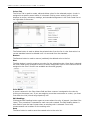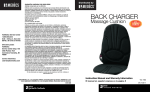
1
VeriColor
®
Identification System
(covers ver. B Hub and ver. 2.0 Software)
Setup and Operation
VERICOLOR
®
IDENTIFICATION
SYSTEM
CE Declaration
Manufacturer's Name:
X-Rite, Incorporated
Authorized Representative:
X-Rite, Incorporated
Siemensstraße 12b • 63263 Neu-Isenburg • Germany
Phone: +49 (0) 61 02-79 57-0 • Fax: +49 (0) 61 02 -79 57-57
Model Name:
Model No.:
VeriColor Identification System
VC100B (Hub)
VC25 (Small Spot Sensor)
VC50 (Medium Spot Sensor)
Directive(s) Conformance:
EMC 89/336/EEC
LVD 73/23/EEC
Note:
This is a class A product. In a domestic environment this product may cause interference in which
case the user may be required to take adequate measures.
RoHS/WEEE
X-Rite products meet the Restriction of Hazardous Substances (RoHS) Directive 2002/95/EC and
European Union – Waste Electrical and Electronic Equipment (WEEE) Directive 2002/96/EC. Please
refer to www.xrite.com for more information on X-Rite’s compliance with the RoHS/WEEE directives.
Federal Communications Commission Notice
NOTE: This equipment has been tested and found to comply with the limits for a Class A digital device,
pursuant to Part 15 of the FCC Rules. These limits are designed to provide reasonable protection
against harmful interference when the equipment is operated in a commercial environment. This
equipment generates, uses, and can radiate radio frequency energy and, if not installed and used in
accordance with the instruction manual, may cause harmful interference to radio communications.
Operation of this equipment in a residential area is likely to cause harmful interference in which case
the user will be required to correct the interference at his own expense.
Industry Canada Compliance Statement
This Class A digital apparatus complies with Canadian ICES-003.
Cet appareil numérique de la classe A est conforme à la norme NMB-003 du Canada.
Equipment Information
Use of this equipment in a manner other than that specified by X-Rite, Incorporated may compromise
design integrity and become unsafe.
WARNING: This instrument is not for use in explosive environments.
ADVERTENCIA - NO use este aparato en los ambientes explosivos.
AVVERTIMENTO - NON usare questo apparecchio in ambienti esplosivi.
WARNUNG: Das Gerät darf in einer explosiven Umgebung NICHT verwendet werden.
AVERTISSEMENT: Cet instrument ne doit pas être utilisé dans un environnement explosif.
1
VERICOLOR
®
IDENTIFICATION
SYSTEM
Proprietary Notice
The information contained in this manual is derived from patent and proprietary data of
X-Rite, Incorporated. The contents of this manual are the property of X-Rite, Incorporated and are
copyrighted. Any reproduction in whole or part is strictly prohibited. Publication of this information
does not imply any rights to reproduce or use this manual for any purpose other than installing,
operating, or maintaining this instrument. No part of this manual may be reproduced, transcribed,
transmitted, stored in a retrieval system, or translated into any language or computer language, in
any form or by any means, electronic, magnetic, mechanical, optical, manual, or otherwise, without
the prior written permission of an officer of X-Rite, Incorporated.
This product may be covered by one or more patents. Refer to the instrument for actual patent
numbers.
Copyright © 2007 by X-Rite, Incorporated “ALL RIGHTS RESERVED”
X-Rite and VeriColor are registered trademarks of X-Rite, Incorporated. All other logos, brand names, and product names
mentioned are the properties of their respective holders.
Warranty Information
X-Rite, Incorporated (“X-Rite”) warrants each instrument manufactured to be free of defects in
material and workmanship for a period of 12 months. This warranty shall be fulfilled by the repair or
replacement, at the option of X-Rite, of any part or parts, free of charge including labor, F.O.B. its
factory or authorized service center.
This warranty shall be voided by any repair, alteration, or modification, by persons other than
employees of X-Rite, or those expressly authorized by X-Rite to perform repairs, and by any abuse,
misuse, or neglect of the product, or by use not in accordance with X-Rite’s published instructions.
X-Rite reserves the right to make changes in design and /or improvements to its products without any
obligation to include these changes in any products previously manufactured. Correction of defects by
repair or replacement shall constitute fulfillment of all warranty obligations on the part of X-Rite.
THIS WARRANTY IS EXPLICITLY IN LIEU OF ANY OTHER EXPRESSED OR IMPLIED WARRANTIES,
INCLUDING ANY IMPLIED WARRANTY OF MERCHANTABILITY OR FITNESS FOR ANY PARTICULAR
PURPOSE. THIS WARRANTY OBLIGATION IS LIMITED TO REPAIR OR REPLACEMENT OF THE UNIT
RETURNED TO X-RITE OR AN AUTHORIZED SERVICE CENTER FOR THAT PURPOSE.
This agreement shall be interpreted in accordance with the laws of the State of Michigan and
jurisdiction and venue shall lie with the courts of Michigan as selected by X-Rite, Incorporated.
2
VERICOLOR
®
IDENTIFICATION
SYSTEM
Table of Contents
Overview and Setup
Instrument Description
Unpacking and Inspection
Setting Up the System
Sensor Installation
Attaching the Alignment Tool to the Sensor
Positioning the Sensor with Alignment Tool
Sensor Vertical Mounting
Sensor Dimension Drawing
Mounting the Hub
Angle Bracket Dimension Drawing
Connecting the Cabling
Hub Defintions
Power Supply Terminals
Local PLC Interface
PLC Input Terminals
PLC Output Terminals
Computer Interfaces
Front Panel Interface
Display (2-digit)
Remote Sensor Interface
Chassis Grounding Post
VeriColor Hub Software Application
Basic System Requirements
Installing the Software
Starting the Application
Application Modes
Connect Mode
Monitor Mode
Compare Mode
Setup Mode
Tools Mode
Device/Logging Controls (bottom screen)
Project Out Of Sync Message
Sensor List Warning Message
5
5
5
6
6
6
7
8
8
9
10
11
12
12
12
12
13
14
14
15
15
15
16
16
16
16
17
17
18
20
21
28
32
33
34
VeriColor Hub Software Operation
35
Manual Hub Operation
42
General Maintenance
46
Learning Standard Colors
Monitoring Sample Measurements
Targeting Mode
Calibration/Verification Mode
Manual Standard Learning Mode
Enabling/Disabling Standard in Manual Mode
Measuring Sample in Manual Mode
Manual Targeting Mode
Restoring Factory Presets in Manual Mode
Repair Information
Cleaning the Hub
Cleaning the Sensor(s)
Cleaning the Calibration Tool
35
36
37
40
42
43
43
44
45
46
46
46
46
3
VERICOLOR
®
IDENTIFICATION
Appendices
SYSTEM
Specifications
Accessories
Hub Electrical Interface Details
RS-232 and RS-485 Electrical Interface Details
Hub to Sensor Electrical Interface Details
Hub 2-Digit LED Display Codes
Error Log in VeriColor Hub Software
Hardware Troubleshooting
Ethernet Notes
Remote Control Interface
General FAQs
4
47
47
48
49
51
51
52
55
59
64
64
65
VERICOLOR
®
IDENTIFICATION
SYSTEM
Overview and Setup
Instrument Description
The VeriColor® Identification System is used to evaluate and identify colors in an industrial
type application. It provides the means necessary to learn (measure) standard colors and
measure samples for comparison. The system uses these comparisons to determine the
closest standard or pass/fail a sample based on a tolerance.
The VeriColor system is composed of three main components: the VeriColor sensor(s) which
captures sample color; the VeriColor hub which provides interface to the sensor(s); and the
software application.
VeriColor Sensor(s)
VeriColor Hub
RS-232 port
RS-485 Port
PLC output terminals
Hub connection
Sensor connection
Additional sensor
connection
2-Digit display
Chassis grounding post
Pass/fail output
terminals
24V Power terminals
PLC Input terminals
Illumination port
Ethernet port
Sensor port
Unpacking and Inspection
After removing the instrument from the shipping carton, inspect it for damage. If any
damage has occurred during shipping, immediately contact the transportation company. Do
not proceed with installation until the carrier’s agent has inspected the damage.
Your instrument was packaged in a specially designed carton to assure against damage. If
shipment is necessary, the instrument should be packaged in the original carton along with
all the accessories. If the original carton is not available, contact X-Rite to have a
replacement shipped to you.
Packaging Contents:
•
•
VeriColor Hub
Sensor
•
•
•
•
Interconnect Cable (3 meter)
Alignment Tool
Calibration Tool
Targeting Stickers (4)
•
•
•
•
•
DIN Rail Mounting Bracket
Flange Mounting Brackets
VeriColor Application Software CD
Setup and Operation Manual
Registration Material
P/N
P/N
P/N
P/N
P/N
P/N
P/N
P/N
P/N
P/N
P/N
P/N
P/N
VC100B-00-01
VC50-00-01 (medium spot) or
VC25-00-01 (small spot)
SE108-EUR8-03
VC50-803
VC100-162
VC50-32 (medium spot) or
VC25-32 (small spot)
VC100-25
VC100-35
VC150-500-CD
VC150B-500
SD01-99
5
VERICOLOR
®
IDENTIFICATION
SYSTEM
Setting Up the System
The setup consists of mounting the sensor(s) and hub, connecting the interface cabling,
powering up the system, and installation the software.
Sensor Installation
An alignment tool is provided with the system to aid in the sensor installation. The tool
simply snaps into position, providing the required angle (30°) and height (1.40”) needed for
proper mounting.
CAUTION: Keep the sensor port lens and illumination port lens free from dust,
smudge marks, and finger prints.
Attaching the Alignment Tool to the Sensor
1.
Position the end of the alignment tool shown over the tab on the sensor port side of
the sensor. The tab should insert into a slotted opening in the tool.
2.
Rotate the other end of the tool upward until it snaps into place over the tab on the
illumination port of the sensor.
Tab
Tab
Illumination port
Sensor port
Alignment guide
NOTE: The alignment tool will only install in one direction.
Correct Alignment
6
Incorrect Alignment
VERICOLOR
®
IDENTIFICATION
SYSTEM
Positioning the Sensor with Alignment Tool
1.
Locate the sensor in the fixture with the flat surface of the alignment tool on the part
to measure. Using the groove that runs along the bottom of the flat surface as a
guide, position the sensor to the desired measurement spot. The groove is the
location where the measurement will take place.
2.
When the sensor is properly located, secure it to the fixture using the four mounting
holes. Remove the part from the fixture.
Mounting hole (4)
Measurement spot
(tool groove)
Sample part
3.
Remove the alignment tool by pulling outward (1) on the sensor port side of the tool
and rotating downward (2).
(1)
(2)
7
VERICOLOR
®
IDENTIFICATION
SYSTEM
Sensor Vertical Mounting
As an alternative to tilted mounting, you can mount the sensor in a vertical position.
However, X-Rite recommends mounting the sensor at a 30° angle utilizing the
alignment tool.
Mounting Hole (4)
Fixture
Sensor
1.40" (±.125)
Sensor Port
Illumination Port
Sample Part
Sensor Dimension Drawing
8
VERICOLOR
®
IDENTIFICATION
SYSTEM
Mounting the Hub
The hub should be mounted in an area where it can be easily viewed and accessed.
The hub is mounted to the DIN rail by means of a channel located at the bottom of the hub.
A DIN rail mounting bracket (included) is required to mount the hub to the DIN rail (see
figure 1). The hub can also be mounted using the flange mounting angle brackets provided.
The brackets are mounted to the side plates of the hub (see figure 2).
The hub must be grounded using the chassis grounding post.
System grounds should be tied to a common grounding bus bar in the enclosure, and to the
Hub enclosure chassis grounding post (figure 1 and figure 2) using low impedance ground
straps. Silver tinned flat copper braid at least 0.25 inches (6 mm) wide is ideal for this
purpose. Use of braid rather than conventional wire is more important on switching power
supplies than linear supplies. Braids are also excellent for EMC purposes, which can better
attenuate RF events. Ideally, such grounding straps should be less than 4 inches (100 mm)
long. The ground strap should be used in addition to any safety ground wires required by
applicable electrical codes. If you use conventional wire be sure that it is multi-strand wire
at least 14 AWG for best results.
Note: If not using a common grounding bus bar system and grounding is accomplished
directly through the enclosure, be sure that the connection between the chassis grounding
post and the enclosure is unimpeded with paint or any other insulated surface. Use of a star
washer is helpful.
Chassis Grounding
Post
Figure 1
Mounting Channel
DIN Rail Mounting Adapter
DIN Rail
9
VERICOLOR
®
IDENTIFICATION
SYSTEM
Chassis Grounding Post
Figure 2
Flange Mounting Angle Bracket (2)
Lock washer (4)
Bracket Screw (4)
Angle Bracket Dimension Drawing
10
VERICOLOR
®
IDENTIFICATION
SYSTEM
Connecting the Cabling
Connect the first cable between the hub and the first sensor. If more than one sensor is
used, connect a cable from the first sensor to the second sensor. Continue the daisy chain
connection method for additional sensors, up to six maximum.
The VeriColor system includes a three meter cable (P/N SE108-EUR8-3). Each additional
sensor includes a one meter cable (P/N SE108-EUR8-1). A 10 meter cable (P/N SE108-EUR810) and a three meter “right-angle” cable (P/N SE108-EUR8-3RA) are also available. Cables
may be daisy chained together to obtain additional lengths.
Female Connector
Male Connector
Sensor Connector
Sensor #2
Sensor #1
Hub
To Sensors #3, #4, #5, & #6
Connect the control lines to the terminal screws and/or communication cables to the I/O
ports. Connect the 24 volt power source to the power terminal screws.
PLC Input Terminals
24v Power Terminal
Enable
Learn
RS232
R S 485
8/D
4/C
Reset A
Lock A
Reset B
Read
Read
Pass
32/F 16/E
Lock B
Std Sel
Common
TM
2/B
PLC Channel
Output Terminals
1/A
Ethernet
VeriColor
RS-485 Port
RS-232 Port
1's
24 V AC / DC
Sensor
10's
Chassis Grounding Post
Ethernet
Port (on
side of unit)
Fail
NC NO C NC NO C
PLC Pass/Fail
Output Terminals
11
VERICOLOR
®
IDENTIFICATION
SYSTEM
Hub Definitions
The hub communicates externally via PLC, computer communications (serial and Ethernet)
and an LED indicator. A basic description of the hub’s connections and controls follows. For
a detailed description of the hub’s electrical specifications, refer to the Electrical Interface
Details in the Appendices.
Power Supply Terminals
The main power input is 24 ± 2 volt @ 50/60 Hz. AC or DC. The AC is converted to DC
internally. There is no polarity connection required. This is a 2-position plug located on the
top left side of the unit and is the main power input: 24 Volts @ 50/60Hz. AC or DC as
described previously. There is an associated LED status indicator contained within the X-Rite
logo (orange triangle). LED indication (Pwr ON) illuminates when power is applied
Local PLC Interface
Local external control between the operator (machine-level) and the hub is through a set of
front panel screw terminals (both input and output signals). These screw terminals are
contained within a 2-part, quick inter-connect system. The 2-piece system consists of a
removable plug that contains the screw terminals and the mating header that’s mounted on
the hub. Several inputs and outputs with their respective status indicators (LEDs) are
available. Refer to figure-1 for front panel layout details and the Appendices for electrical
details.
PLC Input Terminals
There is a 9-position plug (screw terminals) located on the top, right side of the hub. These
are intended as low-voltage discrete control line inputs having bi-directional (isolated)
capabilities. The bi-directionality allows electrical configuration of either pull-up or pull-down
operation.
If the configuration is “pull-up”, you must externally energize the control signal between
+12 and +24-voltage ‘dc’ and when activation is requested, electrically ground that signal
line to zero volts ‘dc’. The other screw terminal input is continuously energized.
If the hub configuration is “pull-down”, you must externally de-energize the control signal
to zero volts ‘dc’ and when activation is requested, electrically energize the control signal
between +12 and +24-voltage ‘dc’. The other screw terminal input is continuously
grounded.
The Lock (lockout) and Reset features have “paired” inputs, while the Discrete Select, 10s,
1s, and Read input control lines utilize a “common” terminal. The “common” terminal will
have the continuously applied level, either energized or grounded. Lock and Reset do not
use the common terminal.
Reset “A” and “B” Input
This input is a hardwired line for local PLC control. Activation is dependent on your
configuration as noted above and uses 2 terminals ‘A’ and ‘B’. Reset is a momentarily
applied condition. Executing a 1 second pulse commands the HUB to process a “softwarereset” operation. There is an associated red LED status indicator that displays operational
information. LED off indicates no action or unit is okay and “red” (LED on) indicates a
“RESET” is occurring.
Lock “A” and “B” (Lockout) Input
This input is a hardwired line for local PLC control. Activation is dependent on your
configuration as noted above and uses 2 terminals “A” and “B”. Lockout MUST be
continuously applied for this function to exist. This action disables all front panel manual
controls, except RESET. There is an associated green LED status indicator. LED off indicates
no action and “green” (LED on) indicates “LockOut” mode active.
12
VERICOLOR
®
IDENTIFICATION
SYSTEM
Read Input (Measure)
This input is a hardwire line for local PLC control. Activation is dependent on your
configuration as noted above, but uses a “common terminal set-up”. Read is a momentarily
applied condition. Executing a 1 second pulse commands the HUB to process a
“measurement” operation. There is an associated green LED status indicator. LED off
indicates no action and “green” (LED on) indicates “Measure” is occurring.
Std Sel (Standard Select), 10’s and 1’s Inputs
This group of 3 hardwired line inputs is for local PLC control. Activation is dependent on your
configuration as noted above using the “common terminal set-up”. There is an associated
green LED status indicator for this group. LED off indicates “discrete standard select” mode
is inactive, LED on (illuminated) indicates active and standards can be selected.
Std Sel (standard select) must be continuously applied for this function to exist. During this
“on” period the ‘10’ and ‘1’ inputs can be pulsed to choose a standard from the ones stored.
Up to 50 standards can be stored.
The ‘10’ input is a momentarily applied condition that will select standards only while std sel
is active. Executing from 1 to 5 pulses will command the HUB to process a “tens digit”
operation. Each pulse has to be ‘on’ between 100 and 200 milli-seconds, then ‘off’ between
100 and 200 milli-seconds. If no pulses happen during the std sel activation, then no “tens
digit” operation occurs.
The ‘1’ input is a momentarily applied condition that will select standards only while std sel
is active. Executing from 1 to 9 pulses will command the HUB to process a “ones digit”
operation. Each pulse has to be ‘on’ between 100 and 200 milli-seconds, then ‘off’ between
100 and 200 milli-seconds. If no pulses happen during the std sel activation, then no “ones
digit” operation occurs.
PLC Output Terminals
There are two multi-position plugs located along the bottom edge of the unit. These plugs
are the hub’s isolated outputs that can control external devices through several screw
terminals. These are low current, relay style outputs. “LockOut” does not affect these
controls.
Fail Output (3 connections)
This output group is activated to indicate that a “fail” resulted after processing a measure
command, with the resulting reading being out of tolerance. The output group has a
normally closed and open set of relay contacts, with a common input line. The default state
during power-up and reset is the normally closed contact. There is an associated red LED
status indicator. LED off indicates no action and “red” (LED on) indicates “FAIL” active.
Pass Output (3 connections)
This output group is activated to indicate that a “pass” resulted after processing a measure
command with the resulting reading being in tolerance. The output group has a normally
closed and open set of relay contacts, with a common input line. The default state during
power-up and reset is the normally closed contact. There is an associated green LED status
indicator. LED off indicates no action and “green” (LED on) indicates “PASS” active.
Channel Outputs (12 connections)
This output group can be activated after processing a hub command or during set-up. The
output activation can control an external device indicating that an action is required. The
“action” will be on or off. There are 6 outputs that can be used individually, in a base-2
feature (binary coding), or in a “paired” combination (user defined). These outputs are the
closure of the normally open contacts of a relay. The default state during power-up and
13
VERICOLOR
®
IDENTIFICATION
SYSTEM
reset is “open.” Each channel (output) has an individual common signal return for industrial
isolation.
The status indicators are bi-color LEDs that display resulting information in the form of color
states to the user. Color not displayed (LED off) indicates no result or unit is not active. A
color “on” indicates the feature is active. Red indicates “state = 0”, Green indicates “state
=1”, relay “on.” Amber indicates channel programmed (relay is not active).
Computer Interfaces
Computer (PC) communication between the user and the hub can occur by one of two
methods: standard RS-232 or a 10 MB Ethernet connection. The RS-485 port is an optional
input, intended for PLC use.
RS-232 Interface
The computer interface is through a standard computer RS-232 port using a DB-9 connector
(also see the Appendices). The communications protocol is serial using X-Rite’s RCI
command set, which is in a separate document.
Ethernet Interface
An additional computer interface can be through a 10 MB Ethernet connection port (RJ45).
RS-485 Interface (programmable logic controller)
An industrial computer interface (for PLC control) can be through the RS-485 port (DB-9
connector); also see Appendix-B. This interface can externally control the hub through serial
communications, but must be configured by the user using the standard X-Rite RCI
protocol.
Front Panel Interface
Manual hub operation can be established through the front panel to allow control and/or
set-up of the system. Several switches with their respective status indicators (LEDs) are
available. Refer to Connecting the Cabling section for front panel layout/button location
details, and Manual Hub Operation section for operational mode details.
Reset Button
This is a momentary push-button. Activation generates a signal that commands the hub to
process a “RESET” operation. It momentarily re-cycles the internal power supply. “Lockout”
does not affect this control. There is an associated red LED that illuminates to indicate when
in a reset condition.
Enable
Enable Button
This is a momentary push-button. Activation generates a signal that commands the hub to
process an “enable” operation. Note that when “Lockout” is active, it prevents this front
panel control from operating. There is an associated green LED status indicator that displays
operational information. LED off indicates no action and “green” (LED on) indicates
“ENABLED.”
and Down Button
Select Up Button
These are momentary push-buttons. Activation of either generates a signal that commands
the hub to process either a “select-up” or “select-down” operation. Note that when
“Lockout” is active, it prevents these front panel controls from operating. There is an
14
VERICOLOR
®
IDENTIFICATION
SYSTEM
associated 2-digit display that indicates operational information, and as button activation
occurs, changes to the display indicate “Select-up or Select-down” respectively.
Learn
Learn Switch
This is a momentary, push-button switch. Activation generates a signal that commands the
hub to process a learn operation. Note that when “Lockout” is active, it prevents this front
panel control from operating. There is an associated red LED status indicator that displays
operational information. LED off indicates no action and “red” (LED on) indicates “LEARN”
mode.
Read
Read (Measure) Switch
This is a momentary, push-button switch. Activation generates a signal that commands the
hub to process a measure operation. Note that when “Lockout” is active, it prevents this
front panel control from operating. There is an associated green LED status indicator that
displays operational information. LED off indicates no action and “green” (LED on) indicates
a “MEASURE” function is occurring.
Display (2-digit)
The display module indicates numbers 0 to 99. The display is typically used to indicate the
current standard number of 1 through 50. In targeting mode, it displays a two digit ΔLED
value. ΔLED values from 0.0 to 9.9 can be displayed.
ΔLED is an algorithm developed by X-Rite to describe color difference without factoring in
illumination or eye response. As with Delta E CIELab, it attempts to describe a minimum
noticeable difference as a value of 1.0.
Remote Sensor Interface
The remote sensors use daisy-chain communications and control signals (serial) that are
presented through one I/O port on the hub. The connector is a non-standard (mini-circular,
6-pin DIN), employing the RS-422 standard. The hub automatically assigns sensor
identification in the order they are located in the communications chain. Refer to the
Appendices for electrical details.
Chassis Grounding Post
The “chassis” grounding post located near this power input is used for grounding the hub.
The chassis grounding post must be used to ground the hub. Without this connection,
remote sensor measurements may be sensitive to nearby noise sources.
Refer to Mounting the Hub described earlier in this manual for additional information on
grounding.
15
VERICOLOR
®
IDENTIFICATION
SYSTEM
VeriColor Hub Software Application
The VeriColor system includes a software application that provides an interface for the
VeriColor Hub. The application is used to configure the hub, store projects which consist of
standard colors, and provide visual feedback of sample measurements.
Before installing the software, make sure the sensor(s) and hub are set up as explained
earlier and the hub is connected to serial port or Ethernet on the computer.
Basic System Requirements
•
Windows OS (2000 or greater)
•
Minimum screen resolution (1024x768)
Installing the Software
The software uses a standard Windows installation procedure.
1. Insert the software CD into your computer's CD-ROM drive. The setup should start
automatically. If it does not start automatically, double-click the setup.exe file on
the CD.
2. The setup program guides you through the rest of the installation process. Follow the
instructions on each setup screen to complete the installation.
Starting the Application
The software application can be launched using the “VeriColor” short-cut on your desktop or
from within the Programs> X-Rite application group.
(First screen that
appears when the
application is
started)
The following pages provide you with a detailed overview of the software application. You
can also refer to the on-line help system within the application for operation instruction. The
help system can be accessed at any point in the application by clicking the Help button at
the top of the screen.
Refer to the Operation section for information on using the application with the VeriColor
system.
16
VERICOLOR
®
IDENTIFICATION
SYSTEM
Application Modes
The X-Rite VeriColor Hub application is divided into six main modes, which are navigated by
using the six buttons located at the top of the screen.
•
Connect – used to establish connection to the VeriColor Hub
•
Monitor – used to monitor sample measurements after the system is set up
•
Compare – used to compare sample measurements without storing sample data
•
Setup – used to create projects and color standards
•
Tools – used to access the device name, targeting, calibration, log file, etc.
•
Help – used to access online help for the displayed dialog
Connect Mode
The Connect screen is used to establish either serial or Ethernet communications with the
hub. Offline browsing can also be used at this screen.
Communication between the hub and computer is established in one of two ways.
1) Selecting the known COM port using the Serial Port control or clicking Auto Connect
2) Selecting a previous IP address from the Ethernet control or typing in an IP address.
With either case, the Connect button is clicked to establish the connection. Refer Ethernet
Notes in the Appendices for additional information on Ethernet setup.
The Off-line Browsing control lists all the hubs that have locally stored projects. When a
hub is selected, the program switches to the Setup screen where the projects can be viewed
and edited.
17
VERICOLOR
®
IDENTIFICATION
SYSTEM
Monitor Mode
The Monitor screen is the “main” mode of the application. The Monitor mode is used to view
measurement results once the projects, colors and standards are setup. Sample results
from measurements activated remotely also appear on this screen.
Measure
The Measure button is used to activate a measurement by the Hub.
Standard Selection
The current standard used by the Hub is displayed at the Sensor Overview window of the
screen. The same control can be used to select a different standard if more than one exists
in the current project.
Sensor Overview
The Sensor Overview area displays a color wheel window for each sensor, or a color wheel
window for a collection of sensors knows as a VLA (Virtual Large Aperture). Each color
wheel window shows the sensor, pass/fail status, tolerance, and ΔLED or ΔIntensity and
ΔColor values.
When a color wheel window is clicked on in the Sensor Overview area, the zoomed view of
the color wheel window selected is displayed in the Detail View of Sensor window on the
right side of the screen.
Detail View of Sensor
The Detail View window contains a color wheel and bar graphs that displays the ΔLED or
ΔColor and ΔIntensity values.
The bar graphs display ΔLED or ΔIntensity and ΔColor values between the current sample
and standard color. The graph displayed is dependent on the current color’s active tolerance.
You can switch between graph modes by clicking on either tab at the top of the graph.
18
VERICOLOR
®
IDENTIFICATION
SYSTEM
•
ΔLED represents the total color difference from a learned standard
•
ΔIntensity represents the difference in light/dark, black/white, or changes in gloss
and/or appearance
•
ΔColor represents the difference from a learned standard moving in any direction to
red/green or blue/yellow (change in color hue)
ΔIntensity and ΔColor mode would be used when measuring parts that have the most
variable intensity changes, such as textiles.
Each graph contains a colored bar with a dotted tolerance line. The bar is the value and the
dotted line represents the current tolerance value. The bar’s color can be green (Pass), red
(Fail) or blue (no tolerance).
These graphs are automatically scaled depending on the circumstance. For most cases, the
graph is scaled to the tolerance or value, whichever is greater. There are a few exceptions
to this rule but they will be described in each mode.
The color wheel allows direct comparison between the standard color and sample
measurements. The color wheel utilizes automatic and manual controls for adjusting the
scaling of the standard color and sample. In auto mode each new measurement adjusts the
scale automatically. If one of the scaling arrows is scrolled, the graph updates as the bar is
moved. This causes the auto button to turn off.
The center point of the circle represents the origin or the bottom range of the scale, while
the color bars at the edges represent the top range. The greatest benefit of graphing two
colors at once is that it gives you the ability to discern color differences (bluer, darker,
greener, etc).
Notes
The Note box at the bottom-right of the screen is used to enter information for the current
measurement displayed. The information is added to a column in the log file.
Enter the information in the field and click Enter to include a note.
19
VERICOLOR
®
IDENTIFICATION
SYSTEM
Compare Mode
The Compare mode is useful for quickly determining the color difference between two
separate measurements. Measurements taken on this screen do not affect the current
setup, log file, or require the hub to be setup with a project.
Measure 1 and Measure 2
A measurement taken using the Measure 1 button is displayed as Measure 1 data, and a
measurement taken using the Measure 2 button is displayed as Measure 2 data. The results
displayed are the differences between Measure 1 and Measure 2. The last measurement
taken using either button remains current until the application is restarted.
Sensor Overview and Detail View Windows
The bar graphs and color wheels display the same as in the Monitor mode without
tolerancing. The color wheel controls are the same as on the Monitor screen.
20
VERICOLOR
®
IDENTIFICATION
SYSTEM
Setup Mode
The Setup mode is used to create projects, standards and their colors. A single project can
consist of up to 50 standards and configuration settings. Once created, a project is
downloaded and stored in the hub. Once the hub is programmed with a project, it can be
executed independent of the software application. See Manual Hub Operation later in this
manual for an explanation.
The following is an example of a project setup. Standard #1 consists of color #1 with
sensors A, B and C assigned as a VLA (virtual large aperture.) Standard #2 consists of two
colors with individual sensors (C and D) assigned to each color.
Project #1
Standard #1
Color #1
Sensor A
Sensor B
VLA Setup with Color #1
Standard #2
•••••>
Color #2
Color #3
Sensor C
Sensor D
•••••>
More Standards
(up to 50)
More Colors
Additional Sensor
Assignments
Single Color/Sensor Setup
21
VERICOLOR
®
IDENTIFICATION
SYSTEM
Project Selection
The current project name is displayed at the top portion of the screen. The same control can
be used to select a different project if more than one exists.
New Project
The New Project button is used to create a new project. Once clicked, you are prompted to
enter a new project name.
Delete Project
The Delete Project button is used to delete the currently selected project. Deleted projects
cannot be restored.
Pass/Fail Indicator
The Pass/Fail Indicator option is used to assign a pass/fail status to each sample
measurement, based on the tolerancing. Selecting On activates this option and selecting Off
disables this option.
Auto Select Standard
The Auto Select Standard option allows the hub to select the closest standard from the list
of standards in the project during sample measurements. Selecting On activates this option
and selecting Off requires you to manually select the standard before a sample
measurement.
Advanced Options
The Advanced Options screen contains several project options that you typically do not have
to change. The options are contained in three tab pages that are selected at the top of the
screen. After the options are set, the Done button is clicked to return you back to the main
Project Setup screen.
Input Operations Tab
Averaging (Sampling)
Determines the amount of measurement taken to obtain an average, and how much
time elapses between measurements. The averaging control can be turned off (set to
one), or adjusted from 2 to 10 measurements to average. Time delayed between
measurements can be set from Manual to 9.9 seconds. When the control is set to
manual, the measure button much be clicked to take the measurement. When set to
a time increment, the hub will pause between measurements.
Measure Trigger Delay (PLC input)
Determines the amount of time the hub will “pause” after receiving a measure
command from the PLC. The control can be adjusted from 0 to 2.0 seconds.
Digital Filtering
The Digital Filtering option is an alternative to simply averaging a set of readings. This
method applies a weighting factor across multiple readings. The option can be set to
off, or from a range of 2 to 21.
22
VERICOLOR
®
IDENTIFICATION
SYSTEM
Sensor Measure
Determines how the measurements are taken when more than one sensor is used.
Measurements can be taken simultaneously (all sensors at the same time) or
sequentially (one after the other), starting with the first sensor.
Output Operations Tab
Programmable Output
This option configures the hub such that the LED for each sensor either represents
the Standard number (in binary) or the Pass/Fail status of each sensor. If set to
Pass/Fail status, the Make Output Active option become available.
The Make Output Active on toggles between normally closed and normally opened for
the pass and fail output options.
Output Timeout
Determines how long the instrument holds its outputs active after a measurement
occurs. This setting can range from Off to 10 seconds at a one-second increment.
Search Method Tab
Set Search Importance
The Set Search Importance group box contains a series of vertical sliders that
represent the search priority for each sensor in the project. Each slider is labeled
with the name of the sensor and a pictorial representation. The highest priority is at
the top of the scale with the least being at the bottom. The search priority can be set
the same for more than one sensor. Search importance can also be set to Off for
individual sensors. However, one sensor must always be set with a priority.
Standard Search
Determines which math formula is used by the software and the hub to find the next
closest color in the project. The method can be set to ΔLED, ΔColor or ΔIntensity. The
hub uses it for determining the closest color after a measurement, and the software
uses this setting during the Learn mode (to help with Auto Max tolerancing).
23
VERICOLOR
®
IDENTIFICATION
SYSTEM
Colors Tab
The Colors Tab is used to create, edit and delete colors for the selected project. A color is
assigned to a specific sensor before it is learned. Clicking on an existing color in the list
displays its sensor, tolerance, readings, and standard assignment in the Color Detail list on
the right side of the screen.
Delete
The Delete button is used to delete the selected color from the list. A color that exists in a
current standard cannot be deleted until it is removed from the standard.
Restore
The Restore button is used to restore (undelete) the deleted color to the list.
New
The New button is used to create a new color for the selected project. Once New is selected,
the Color Detail group changes to allow for sensor assignment. One or more sensors can be
assigned to the color. Sensors not available are dimmed (grayed).
Color Name
A name is entered in the Color Name field and then a sensor is assigned to the color by
clicking on the sensor icon. If you are assigning more than one sensor to a color, you must
first check the VLA (Virtual Large Aperture) box.
Edit Readings
Clicking the Edit Readings button opens a screen where the color is learned. (see New Color
Learn). This procedure is repeated for each new color created. The Edit Reading button is
also used to open the learn screen when an existing color is selected. From here,
measurements can be taken for the existing color.
Save
The Save button is used to save the created color to the color list.
24
VERICOLOR
®
IDENTIFICATION
SYSTEM
New Color Learn (this screen appears when the Edit Readings button is clicked)
The learn screen allows you to create new colors or edit existing colors from a project. The
purpose of this screen is to take several measurements that are averaged together to
represent a standard color. You can work from a history of measurements and determine
which ones are used to average into the color. This screen assists you in selecting the best
tolerance values for reliable performance and color identification. You can view the
measurement data as ΔLED or ΔIntensity and ΔColor by selecting the tabs at the top of the
screen.
Measure
The Measure button is used to activate a measurement by the hub on the color. Each time
the button is clicked, a measurement is taken and results are appended to the end of the
bar graph and automatically accepted. The new measurement becomes the selected
measurement and all graphs are updated.
Import
The Import button is used to import a sample from a stored log file for use as a color. The
log file can be opened in Excel first to obtain the desired line number.
Accept/Decline
The Accept and Decline buttons are used to characterize each measurement as counting
towards the standard color or not. Accepted readings are displayed in green or red (if they
exceed the tolerance value) on the bar graph, while declined measurements are displayed
as gray bars. Simply click the measurement in the graph and select either button. Once a
measurement is selected in the graph, the color wheel graph updates to show the selected
reading versus the calculated standard color.
Delete
The Delete button is used to remove the selected measurement from the bar graph.
Done
After the color is set, the Done button is clicked to return you back to the Colors page of the
Setup screen where the color can be saved.
25
VERICOLOR
®
IDENTIFICATION
SYSTEM
Tolerancing
The tolerance bar and dotted line on the graph represent the tolerance value. There are
three tolerancing methods that you can choose from for the standard.
Auto Max
This tolerance is determined by setting a mid point to the next closest Color existing in
the project. The area below the color wheel graph contains information on how far or
close the next closest color is. This is the default method, and allows the most buffer
space between colors in a project. Use this when trying to identify colors.
Auto Min
This tolerance is determined by a certain margin over the worst deviating measurement
vs. the standard color. This would be used if you have a certain acceptable production
color variation but want to catch parts that were off color.
Manual
This setting allows you to manually set the tolerance by dragging the tolerance bar up
and down, or by clicking on the field next to the Manual option and entering a value.
Standards Tab
The Standards Tab is used to create, edit and delete standards for the selected project after
colors are created. Up to 50 standards can exist in a project. Standards can be dragged to
new locations in the list. Clicking on an existing standard in the list displays its sensor and
color assignments in the Standards Detail list on the right side of the screen.
Delete Standard
The Delete Standard button is used to delete the selected standard from the list. The other
standards in the list are unaffected when a standard is deleted and retain their positions.
Restore Standard
The Restore button is used to restore (undelete) the deleted standard to the list.
Creating a New Standard
Click in a blank standard position in the list to create a new standard. Once a blank position
is selected, the Standard Detail group clears to allow you to assign a color/sensor to the
new standard.
26
VERICOLOR
®
IDENTIFICATION
SYSTEM
Standard Name
A name is entered in the Standard Name field and then a color is assigned to the sensor(s)
by clicking on the Sensor icon. Sensors not available are dimmed (grayed).
When the Sensor icon is clicked, a list of available colors that where created using the
selected sensor displays. Select the color from the list that will be assigned to the standard
and click OK.
Continue with additional color/sensor assignments as needed.
Save
When finished assigning colors to sensors, click the Save button to save the new standard.
The new standard saved will be placed in the Standard list on the left side of the screen.
Reset
The Reset button is used to return the colors assigned to each sensor back to their original
settings. If this is a new standard, then the sensors are set to no assigned colors.
27
VERICOLOR
®
IDENTIFICATION
SYSTEM
Tools Mode
The Tools mode is used to access instrument information, communication setup, targeting
procedure, calibration procedure, and the log file.
Device Tab
The device tab provides the status for the hub and each sensor, and a list of errors. Factory
setting can also be restored on this tab page.
Name Group
The device group provides the ability to edit the instrument’s name. Enter a name in the
device name field and click Apply.
The Revert button is used to change the device name back to the name it was before it was
changed.
Errors Group
The Clear Errors button will clear the errors shown in the Error list and remove the errors
stored in the hub.
The Print Report button will print all error shown in the list to the default printer.
Factory Settings Group
Clicking the Restore Factory Settings button will restore the hub to its default configuration.
Lock Device Buttons Group
The Lock Device Buttons group is used to lock the PLC Input and Software Command. The
option button toggles between On and Off. When the button is On the option is disabled,
and when the button is Off the option is enabled.
28
VERICOLOR
®
IDENTIFICATION
SYSTEM
Communications Tab
This communications tab is used to configure the Ethernet connection. Consult your IT
department for specific setting requirements.
Targeting Tab
The targeting tab provides a “wizard” format that takes you through a number of steps
required to verify sensor(s) positioning on a part.
Targeting the sensor(s) in conjunction with the software application will be covered in
greater detail in the Operation section later in this document.
29
VERICOLOR
®
IDENTIFICATION
SYSTEM
Calibration Tab
The calibration tab provides a “wizard” format that is used to verify sensor(s) performance
and calibrate the sensor(s) if needed.
Verifying sensor performance and calibration will be covered in greater detail later in the
Operation section of this document.
Log File Tab
The log file tab displays details on the log file. You can view, archive, and clear the current
log, as well as past log files.
Current Log Group
The Current Log group displayed is the log file in use by the current project in the hub.
The View Log button launches an Excel viewer of the current log file.
The Clear Log button empties the current log information. Deleted log files cannot be
restored.
The Archive control allows you to determine how frequently log files are automatically
archived to the hard drive and a new one started. Log file names are based on the project
name and current date. The directory name is based on the hub’s serial number. You can
archive based on Time (weekly, bi-weekly or monthly) or Size (small, medium or large).
30
VERICOLOR
®
IDENTIFICATION
SYSTEM
The Archive button allows you to manually archive the current log file at anytime. You can
rename the file if desired and determine where it should be saved.
Past Logs Group
The Past log control allow you to selected previously stored log files.
The View Archive button is used to view the selected log file.
The Delete Archive button is used to delete the selected log file. Deleted log files cannot be
restored.
31
VERICOLOR
®
IDENTIFICATION
SYSTEM
Device/Logging Controls (bottom screen)
The bottom of the screen contains the Project, Device, and Log controls.
Sensor(s) appear when the orange arrow is clicked.
Project Fields
Contains the following fields:
•
Active: Name of the current project loaded in the hub.
•
Standards Loaded: Current standards loaded in the hub.
•
Auto Select: Displays the status of the auto select feature for the current project.
•
Update Button: Click to download the selected project to the hub.
Device Status Graphic
The status of hub and each sensor is displayed at the bottom of screen. The background
color reflects the current condition of each device. If red appears, the device can be clicked
on to view the error condition information.
•
Green: Device is ready and operating.
•
Yellow: Device is warming up.
•
Red: Device has a system error.
Device (Hub) Fields
Contains the following fields:
•
Status: The status of the hub (Ready, Warming up, or Error).
•
Unit: The name of the hub.
•
Number: The serial number of the hub.
•
Orange Arrow: Click this icon to display the sensor graphics. Clicking a second time
closes the sensor graphics.
Sensor Fields
Contains the following fields:
•
A-F: Indicates the letter of the sensor(s) in use.
•
Number: The serial number of the sensor.
Log File Info
Contains the following fields:
32
•
Log Started: The year-month-day-time that the log file was started.
•
Entries: The number of lines in the log file (out of a maximum number of 10,000).
•
File Name: The name of the log file as it is saved on the computer.
•
Log Start/Stop button: Click the Start button to turn automatic measurement
logging on. When this mode is on, the button changes to "Stop" and each
measurement is recorded in a log file. Click the Stop button to turn logging off.
VERICOLOR
®
IDENTIFICATION
SYSTEM
Project Out Of Sync Message
A project out of sync message appears when the project on the computer and hub do not
match one another. The message that displays depends on which device’s (computer or
hub) project has changed since the last connection.
Computer Project Change
This screen appears when the project in the computer has changed. Clicking the Yes button
causes the changed computer project to overwrite the project in the hub.
Hub Project Change
This screen appears when the project in the hub has changed since the last connection.
Clicking the Yes button causes the changed project in the hub to overwrite the same project
in the computer. A backup copy of the existing project in the computer is automatically
created and stored in the VeriColor projects folder (i.e. “C:\Program Files\VeriColor Hub
System v2.0\Projects”) when Yes is selected.
Computer Project and Hub Project Changed
This screen appears when both the project in the computer and the project in the hub have
changed. Clicking the Download button causes the project in the computer to overwrite the
project in the hub. Clicking the Upload button causes the project in the hub to overwrite the
project in the computer. In the case of an upload, a backup of the current computer project
is created as explained earlier.
33
VERICOLOR
®
IDENTIFICATION
SYSTEM
Sensor List Warning Message
The hub keeps track of the sensors that were used on the selected project via their serial
numbers. If a sensor is changed for example, the serial number of the changed sensor no
longer matches the serial number in the project so a warning message appears. This is also
true if a sensor is added or removed. This check for the current sensor list is made when the
hub is connected to the computer or an attempt is made to download a project from Setups
to the hub.
X-Rite recommends that if sensors are changed the colors should be relearned for the
current project to ensure consistency.
Example of a
warning screen.
Do Not Update Button
Clicking this button will continue with the download and no changes will occur. However,
this message will appear every time you connect to the computer or attempt to download
this project to the hub. Or until the original sensors that match the project are returned to
the hub.
Update Project List Button
Clicking this button will cause the hub to update the sensor list in the current project;
keeping this message from reappearing.
34
VERICOLOR
®
IDENTIFICATION
SYSTEM
VeriColor Hub Software Operation
This section will guide you through the requirements for learning standards, monitoring
samples, targeting, and verifying calibration using the VeriColor Hub software. As
mentioned earlier, you can also access specific information on the application utilizing the
online help system.
For information on operating the hub manually, refer to Manual Hub Operation later in this
document.
Learning Standard Colors
Learning is the method of measuring a color that will be used as a standard color for sample
comparison. Colors are then assigned to standards and downloaded to the hub.
NOTE: When operating in environments above 40°C, the sensor(s) should be calibrated and
standard colors should be learned at the operating temperature to maintain best
performance and color resolution.
Important Learn Mode Notes
As long as the fixture is repeatable (parts placed in the fixture are held in the same position
consistently) one measurement per part should be adequate. Repeated measurements of
the same part without moving/replacing is unnecessary.
Ideally, the part should be taken in and out of the fixture several times and measured to
take into account any positional variations. This does not mean that the part should move
freely under the sensor while measuring various spots. The area measured should be held
consistently.
Identical parts from different lots should also be measured in case their colors vary slightly
between production runs.
1. Start the application and select the Setup screen.
2. Setup new project and configure options. See previous section for information on
performing these tasks.
3. Make sure the Colors tab is selected and click New button.
4. Enter a color name in the Color Name field, assign a sensor(s), and click Edit Readings.
5. Position the part in the fixture (under the assigned sensor) that is to be used for a
standard color.
6. Click the Measure button to take the measurement.
7. Reposition the part (or position a different part) and take additional measurements.
8. Select the desired tolerancing method and accept or decline measurement as needed.
9. When you have finished measuring the standard color to achieve an average, click
the Done button to return to the main project setup screen (Color tab).
10. Click Save to save the color to the color list.
11. Repeat step 3 through 10 to continue with the additional standard colors.
35
VERICOLOR
®
IDENTIFICATION
SYSTEM
Monitoring Sample Measurements
Use the Monitor screen to measure sample parts and monitor the Pass/fail status.
1. Start the application and select the Monitor screen.
2. Verify the correct project is selected. If not, select the desired project from the Setup
screen and click the Update button to upload the project to the hub.
3. If auto color is not used, select the standard that will be used for sample
comparison.
4. Position the sample in the fixture.
5. Click the Measure button to measure the sample. The software will automatically
select the closest standard from the project (if auto color is activated), and display
the result in the bar graph and color wheel(s).
6. Select a sensor color wheel graphic in the Sensor Overview group to view individual
sensor results.
7. Remove the sample and continue with additional sample parts.
36
VERICOLOR
®
IDENTIFICATION
SYSTEM
Targeting Mode
Because the sensor(s) over illuminates, it is sometime difficult to tell exactly where the
sensor is viewing to determine color. This is particularly true for small part measurements.
Targeting a part is the method of adjusting the sensor(s) on the fixture to the required
position for part measurements. Performing the targeting procedure is only needed if the
location of the part to be measured is critical. For example, the measurement area is small
or very close to the spot size of the sensor.
Important Targeting Mode Notes:
Before leaving target mode, test the fixture’s alignment and repeatability by removing and
installing the sample several times as done in a production environment. If the ΔLED’s value
differs significantly when the part is placed in and out, then the fixture needs to become
more precise. Otherwise, the results will be unsatisfactory.
Each time targeting mode is started, the sensor will need to relearn the (white sticker only)
target.
1. Start the application; select the Tools screen and then the Targeting tab.
2. Place the white sticker over the target area of the part you intend on measuring.
3. Place the part in the fixture to begin targeting.
4. Click the icon of the Sensor (A-F) you are targeting and then click Next.
5. Click Next on Step 2 window to start the continuous measurement sequence.
6. Without disturbing the pre-aligned height and angle position of the sensor, carefully
adjust the sensor (x and y coordinates) so the flashing spot is centered in the middle
of the white sticker.
37
VERICOLOR
®
IDENTIFICATION
SYSTEM
White Targeting Sticker
Sample Part
7. After the desired positioning is achieved, click Next on Step 3 window. This takes
the last measurement and saves it as the target value for the sensor.
8. Remove the part from the fixture and remove the white sticker. Place the black ring
sticker in the same location. The black ring is used to help “fine tune” the alignment.
Black Targeting Ring Sticker
Sample Part
Illuminating Spot
9. Place the part back in the fixture and click Next on the Step 4 window.
38
VERICOLOR
®
IDENTIFICATION
SYSTEM
10. View the bar graph on the Step 5 window. If the ΔLED value has increased, you will
need to fine tune the sensor. This is due to the fact that the flashing spot from the
sensor may be measuring part of the black outer ring. If this occurs, fine tune the
sensor to get the smallest ΔLED value possible. Be careful not to change the sensor’s
height and angle adjustment. A ΔLED value of 1.0 or under should be achievable.
11. After the sensor is targeted, click Target Another Sensor to return to the Step 1
targeting window. From here you can target another sensor or exit the targeting
mode.
39
VERICOLOR
®
IDENTIFICATION
SYSTEM
Calibration/Verification Mode
The VeriColor Hub System comes with a calibration tool that is used to verify measurement
performance and for calibrating the sensor(s) if needed. Calibration should be verified
anytime measurement performance is in question. Poor measurement performance can be
caused by dust or dirt on a sensor port. Refer to the Cleaning section later in this document
for procedure on cleaning the sensor.
NOTE: When operating in environments above 40°C, the sensor(s) should be calibrated and
standards should be learned at the operating temperature to maintain best performance and
color resolution.
IMPORTANT: Do not touch the white SRM (Standard Reflection Material) disk inside the
calibration tool. It must be kept clean to ensure accurate measurements. Always store the
calibration tool in its bag when not in use.
1. Start the application; select the Tools screen and then the Calibration tab.
2. The first screen lists information on when the last verification and calibration were
performed on the selected sensor. Click the icon of the sensor (A-F) and then click
Verify to begin the verification process.
3. Snap the “white” end of the calibration tool onto the optics end of the sensor. Make
sure that the white disk is located directly below the illumination port. The
illumination port can be identified by the line that runs along the side of the sensor.
After the tool is properly positioned, click Next on Step 2 window.
SRM Disk
This line must align with
the white SRM disk side
of the calibration tool
40
VERICOLOR
®
IDENTIFICATION
SYSTEM
4. Click Measure on the Step 3 window. The ΔLED bar graph appears and a PASS or
FAIL status is indicated. The tolerancing can be changed by clicking on tolerance
arrow and dragging it up and down to the desired level. Each time the Measure
button is clicked, a new verification test is performed.
5. If the verification passed, remove the calibration tool and click Verify Another
Sensor to return to the first verify window. From here you can verify another sensor
or exit the calibration mode.
If a failure occurred, make sure the calibration tool is on correctly and that the SRM
disk inside the tool is clean. You may also want to clean the illumination port and
sensor port on the sensor. Refer to the General Maintenance section for cleaning
procedures.
After checking the tool and cleaning the instrument, click Measure again to verify
calibration. If a failure still occurs, a calibration will be required. Advance to Step 6.
6. Click the Next button on the Step 3 window to advance to the Step 4 window where
calibration is performed.
IMPORTANT: Calibration should only be performed if absolutely necessary.
Calibrating the sensor may require stored standard colors for that particular
sensor to be relearned.
7. Click Calibrate on the Step 4 window to calibrated the sensor.
41
VERICOLOR
®
IDENTIFICATION
SYSTEM
Manual Hub Operation
In manual mode, inputs from the front panel buttons of the hub or local PLC control the
hub. The hub has limited configuration capabilities along with local control. In local PLC
mode, the hub only runs a predefined sequence program with results displayed locally,
while providing external control signals via relay outputs.
Manual hub operation requires no computer interface. Operation is performed utilizing the
buttons, 2 digit display, and LEDs located on the hub.
Operation of the system consists of three main modes, targeting, learning, and sample
measurements.
For information on operating the hub utilizing the VeriColor hub software, refer to VeriColor
Hub Software Operation earlier in this document.
NOTE: The LOCK (Lockout) input terminal must be disabled for the hub’s panel buttons to
function. Deactivation depends on your choice of pull-up or pull-down configuration. For
status, you can visually reference the ‘lock’ LED to verify the functional state (green
illumination indicates ‘lockout’ is active). Remember, lockout can also be activated through
software or remote commands so they must also be deactivated.
Manual Standard Learning Mode
Learning is the method of measuring a color that will be used as a standard color for sample
comparison. The manual learn mode allows you to measure standard colors and store them
in the hub without using the VeriColor software application. For more advanced setups and
greater control, it is suggested that you use the VeriColor software application when
learning standard colors.
NOTE: When operating in environments above 40°C, the sensor(s) should be calibrated and
standard colors should be learned at the operating temperature to maintain best
performance and color resolution.
Important Learn Mode Notes
As long as the fixture is repeatable (parts placed in the fixture are held in the same position
consistently) one measurement per part should be adequate. Repeated measurements of
the same part without moving/replacing is unnecessary.
Ideally, the part should be taken in and out of the fixture several times and measured to
take into account any positional variations. This does not mean that the part should move
freely under the sensor while measuring various spots. The area measured should be held
consistently.
Identical parts from different lots should also be measured in case their colors vary slightly
between production runs.
1. Position the part in the fixture that is to be used for a standard color.
2. Press the Select Up arrow button or the Select Down arrow button to choose a
location (1-50) to store the standard data.
NOTE: Care should be taken when selecting a standard location. Pre-existing
standards can be easily overwritten in manual learn mode.
The Enable LED indicates whether the selected standard is enabled or disabled. An
illuminating Enable LED indicates the standard is enabled (refer to Enable/Disabling
Standard later in this section for more information). Also, the output LEDs (A-F)
illuminate amber if data is stored for the selected standard. For example, if standard
42
VERICOLOR
®
IDENTIFICATION
SYSTEM
#3 is selected on a two sensor system, LEDs “A” and “B” will light if data is stored in
the location.
3. Press the Learn button once to activate the learn mode. The LED next to the button
illuminates red when learn mode is activated.
4. Press the Read button to take one measurement with all attached sensors. The
standard that is saved in the hub is a collection of measurements (VLA) from all
attached sensors.
5. Additional measurements can be taken on the part to achieve average values by
pressing the Read button as many times as desired.
NOTE: In the standalone learn mode, averaging only occurs within individual
sensors, not across all attached sensors.
A tolerance value of 1.00 is the starting default value and will auto compensate
based on how far any additional measurements deviate from the current average.
The tolerance will never auto adjust below a value 1.00. The VeriColor software must
be used to allow smaller tolerancing.
If a measurement error occurs and you want to restart the measurement sequence
for the standard, simply toggle the selected standard number up or down and then
back.
6. Continue with the next standard by placing the part in the fixture and using the
Select Up or Select Down button to select the standard location.
7. When all required standards have been measured, press the Learn button to
permanently save the standards and exit out of the learn mode. The LED next to the
learn button will go out.
Enabling/Disabling Standard in Manual Mode
Stored standards can be enabled or disabled for a particular project. This is accomplished by
using the Enable button next to the 2-digit display. Use the Select-Up or Select-Down
arrow buttons to choose the standard location. The LED next the Enabled button illuminates
green when the selected standard is enabled. Pressing the Enable button again will disable
the standard (LED not illuminating). When the LED is off, the standard is disabled and will
not be evaluated during a standard search. The standard can be reselected by pressing the
Enable button again. If no standard is stored in the selected location, the LED will not
illuminate when the Enable button is pressed.
Measuring Sample in Manual Mode
This is the mode the hub operates in most of the time. The hub will operate in its default
configuration. Any changes to configuration require the VeriColor software.
After each sample measurement, the closest passing standard (smallest ΔLED) to the
sample becomes the current standard.
If the sample was within tolerance per sensor, then the Pass output LED illuminates. If one
sensor fails its tolerance in a multi sensor fixture, then the Fail Output LED illuminates.
When a measurement passes, the LED Array Output will illuminate with green lights
(activating the output relays) as the binary representation of the Standard number.
If a measurement fails, the LED Array Outputs will all turn off (if they aren’t already).
Outputs LEDs illuminate for 15 seconds (default setting) after a measurement or until a new
measurement is taken.
43
VERICOLOR
®
IDENTIFICATION
SYSTEM
1. Determine what standards are to be used for sample comparison if required (see
Enabling/Disabling Standards).
2. Position the sample in the fixture.
3. Press the Read button to activate the sensor(s) measurement. The hub
automatically selects the closest standard and displays the select standard number
on the 2-digit display and binary LEDs.
4. Repeat above steps to measure additional samples.
Manual Targeting Mode
Because the sensor(s) over illuminates, it is sometime difficult to tell exactly where the
sensor is viewing to determine color. This is particularly true for small part measurements.
Targeting a part is the method of adjusting the sensor(s) on the fixture to the required
position for part measurements. Performing the targeting procedure is only needed if the
location of the part to be measured is critical. For example, the measurement area is small
or very close to the spot size of the sensor.
Important Targeting Mode Notes:
Before leaving target mode, test the fixture’s alignment and repeatability by removing and
installing the sample several times as done in a production environment. If the ΔLED’s value
differs significantly when the part is placed in and out, then the fixture needs to become
more precise. Otherwise, the results will be unsatisfactory.
Each time targeting mode is started, the sensor will need to relearn the (white sticker only)
target.
1. Place the white sticker over the target area of the part you intend on measuring.
2. Place the part in the fixture of the first sensor to begin targeting.
3. Simultaneously press and hold the Read button and the Learn button on the hub
until targeting mode is entered. Targeting mode is indicated by:
- Learn LED illuminating red
- Output LED “A” illuminating amber
- 2-digit display fluctuating values (example, 8.9, 9.9, etc.)
- First sensor taking rapid measurements (2 per second)
4. Without disturbing the pre-aligned height and angle position of the first sensor,
carefully adjust the sensor (x and y coordinates) so the flashing spot is centered in
the middle of the white sticker.
White Targeting Sticker
Sample Part
Illuminating Spot
5. After the desired positioning is achieved, press the Learn button. This takes the last
measurement and saves it as the target value for the sensor. The 2-digit display
should indicate 0.0 as long as the fixture is stable.
44
VERICOLOR
®
IDENTIFICATION
SYSTEM
6. If additional sensors require targeting, press the Select Up or the Select Down
arrow buttons to advance to the next sensor and repeat steps 4 and 5.
7. Remove the part from the fixture and remove the white sticker. Place the black ring
sticker in the same location. The black ring is used to help “fine tune” the alignment.
8. Place the part back in the fixture and select the first sensor using the Select Up or
the Select Down arrow buttons.
9. The value indicated on the 2-digit display will more than likely increase. This is due
to the fact that the flashing spot from the sensor may be measuring part of the black
outer ring. If this occurs, fine tune the sensor to get the smallest ΔLED value
possible. Be careful not to change the sensor’s height and angle adjustment. A ΔLED
value of 2.0 or under is considered acceptable.
Black Targeting Ring Sticker
Sample Part
Illuminating Spot
10. Press the Select Up or the Select Down arrow buttons to advance to the next
sensor and repeat step 9.
11. After all sensors are targeted, simultaneously press the Learn button and Measure
button to exit targeting mode.
Restoring Factory Presets in Manual Mode
Factory Presets are restored by pressing and holding (approx. 2 seconds) the Up arrow,
Down arrow, and Enable buttons simultaneously. The output LED array illuminates amber
and then red. At this point, the Factory Settings are restored. The reset process can be
aborted by releasing the buttons before the LED’s illuminate red. Restoring Factory Presets
clears following data:
•
•
•
•
•
Master Sensor List
All Standards, Projects, and Fixture data
Configuration settings
Communication settings (Ethernet defaults to Off and must be setup again from
software, and RS-485 Serial port’s Baud rate defaults back to 19200)
Customer calibration data
Performing a factory preset does not clear the hub and sensor serial numbers. Reset the
hub after performing a factory preset. Refer to Front Panel Interface section for procedure.
45
VERICOLOR
®
IDENTIFICATION
SYSTEM
General Maintenance
Repair Information
The VeriColor Identification System is covered by a one-year limited warranty and should be
referred to the factory or an authorized service center for repairs within the warranty
period. Attempts to make repairs within this time frame may void the warranty.
X-Rite provides a factory repair service to their customers. Because of the complexity of the
circuitry, all repairs should be referred to the factory or an authorized service center (call:
1-888-826-3042 or fax: 1-616-534-0067).
X-Rite will repair any instrument past warranty. Shipping cost to the factory or authorized
service center shall be paid by the customer.
Cleaning the Hub
Normally, use low-pressure air to blow away any dust or debris between the connectors and
top surface.
Cleaning the Sensor(s)
Normally, use low-pressure air to blow away any dust or debris on the lenses (or use a soft
lens brush).
To remove dirt or finger prints, clean with a soft cotton cloth rubbing in a circular motion.
Use of a coarse cloth or unnecessary rubbing may scratch the lens surface and eventually
cause permanent damage.
For a more thorough cleaning, photographic lens tissue and photographic-type lens cleaning
fluid or isopropyl alcohol may be used. Always apply the fluid to the cleaning cloth – never
directly on the lens.
Cleaning the Calibration Tool
Caution should be used not to touch the SRM (Standard Reflection Material) disk.
ONLY use clean, dry compressed air to remove any contaminates from the SRM disk in the
calibration tool.
Store the calibration tool in the bag provided when not in use.
SRM Disk
46
VERICOLOR
®
IDENTIFICATION
SYSTEM
Appendices
Specifications
General
Instrument Type: ........................ Hi-Res Reflective Color
Geometry: ................................. 0°/30°
Measurement Area: ..................... 12 mm (.5 in.) or 6 mm (.25 in.) spot sizes
Color Difference Resolution: ......... 0.25 ΔLED, typical (ΔLED is a proprietary color
difference calculation which is based on VeriColor
LED color response and is scaled similar to CIE ΔE*
for small color differences.)
Operating Temp:......................... 0° - 50°C (32° – 122°F)1
Operational Humidity:.................. 0 - 95% non condensing
Hub Size:................................... L: 6.9” (17.5 cm), W: 4.2” (10.7 cm),
H: 3.2” (8.1 cm)
Hub Weight: ............................... 20 oz (670 g)
Sensor Size:............................... L: 5.1” (13 cm), W: 2.9” (7.4 cm),
H: 1.3” (3.3 cm)
Sensor Weight: ........................... 12 oz (338 g)
Power Source: ............................ 24V @ 50/60 Hz., AC or DC, 2.5 Amps Max.
Performance
Black Repeatability:..................... 0.3 ΔLED (1% reflectance black)
0 - 40°C (32 - 104°F)1
White Repeatability: .................... 0.05 ΔLED (99% reflectance white)
0 - 40°C (32 - 104°F)1
Measurement Distance................. 35 mm ±5 mm (1.4 in. ±.2 in.)
Measurement Time:..................... 250 ms
Cycle Time: ................................ 1 sec. (time interval between measurements)
LED Illuminator Life:.................... Life of the unit
Environmental
Usage: ...................................... Indoor Only
Altitude: .................................... 2000m
Pollution Degree: ........................ 2
Overvoltage: .............................. Category II
Enclosure
Sensor: ..................................... Designed to meet NEMA 4 / IP56
Hub: ......................................... Designed to meet NEMA 12 / IP52
Vibration:................................... 5 – 10 Hz 0.200 inch displacement pk - pk
10 – 500 Hz at 1G
Shock:....................................... Operational at 15 g amplitude 18 ms duration
Non-Operational at 30 g amplitude 11 ms duration
Package Drop: ............................ NSTC Project 1A
47
VERICOLOR
®
IDENTIFICATION
SYSTEM
Safety Compliance
Underwriters Laboratories: ........... UL 61010-1
Canadian Standards Assoc: .......... CSA 22.2 No. 1010.1-92
International Electrotechnical
Committee ................................. IEC (EN) 61010-1
1When operating in environments above 40°C, the instrument should be calibrated and standards should be learned
at the operating temperature to maintain best performance and color resolution.
Design and specifications subject to change without notice.
Accessories
The following accessory items can be purchased from X-Rite by calling 1-888-826-3042 or
by visiting our website at: www.xrite.com.
48
1 Meter – Interconnect Cable (8 circuit)
P/N SE108-EUR8-1
3 Meter – Interconnect Cable (8 circuit)
P/N SE108-EUR8-3
10 Meter – Interconnect Cable (8 circuit)
P/N SE108-EUR8-10
1 Meter – Right-angle Interconnect Cable (8 circuit)
P/N SE108-EUR8-1RA
Medium Spot (.50”) Targeting Sticker Kit
P/N VC50-32
Small Spot (.25”) Targeting Sticker Kit
P/N VC25-32
VERICOLOR
®
IDENTIFICATION
SYSTEM
Hub Electrical Interface Details
These are the 2-part screw terminal blocks used for power input and local PLC interfacing.
The hub interface has the following screw terminal Inputs and Outputs:
(Looking left to right from top view)
Item
Location
Name
Description
--
Top
(left)
Power +
--
Top
Power -
15=Input 6
Top
PLC-1 //
“1’s”
24 Volts AC or +24
Vdc . Related LED
status indicator.
24 Volts AC or DC
Ground
PLC screw terminal
Active
State
Comments
Power supply
2.1-amps max.
Power supply
Either (+24
Vdc)
15 –ma. Max.
<normal high/pull
low>
<normal low/pull
high>
14=Input 5
Top
PLC-2 //
“10’s”
PLC screw terminal
Either (+24
Vdc)
15 –ma. Max.
<normal high/pull
low>
<normal low/pull
high>
I3=Input 4
Top
PLC-3 //
“Discrete
Select”
PLC screw terminal
15 –ma. Max.
<normal high/pull
low>
<normal low/pull
high>
--**
Top
Signal
Common
Common (PLC screw
terminal)
I2=Input 3
Top
READ /
Measure
PLC screw terminal or
Manual command push
button
** 12 – 15
Either (+24
Vdc)
--
Top
Lockout-B
**Uses a common
return path
PLC screw terminal
I1=Input 2
Top
Lockout-A
PLC screw terminal
COMMON
Signal return
// 12 - 15
Either (+24
Vdc)
15 -ma. max.
<normal high/pull
low>
<normal low/pull
high>
Signal return
// isolated
pair
LOW (+12V
base)
15 -ma. max.
<normal high/pull
low>
--
Top
Reset-B
PLC screw terminal
I0=Input 1
Top
Reset-A
PLC screw terminal or
Manual command push
button. Related LED
status indicator.
Signal return
// isolated
pair
LOW (+12V
base)
15 -ma. max.
<normal high/pull
low>
49
VERICOLOR
®
IDENTIFICATION
SYSTEM
(Looking right to left from top view)
Item
Location
Name
--
Bottom
(right)
Bottom
Fail -C
(common)
Fail -NO
O1 =
Output 2
Bottom
Fail -NC
--
Bottom
O2 =
Output 3
Bottom
Pass -C
(common)
Pass -NO
O3 =
Output 4
Bottom
Pass -NC
O4 =
Output 5
Bottom
ChnA -NO
--
Bottom
O5 =
Output 6
Bottom
ChnA -C
(common)
ChnB -NO
--
Bottom
O6 =
Output 7
Bottom
--
Bottom
O7 =
Output 8
Bottom
--
Bottom
O8 =
Output 9
Bottom
--
Bottom
O9 =
Output 10
Bottom
--
Bottom
O0 =
Output 1
50
ChnB -C
(common)
ChnC -NO
ChnC -C
(common)
ChnD -NO
ChnD -C
(common)
ChnE -NO
ChnE -C
(common)
ChnF -NO
ChnF -C
(common)
Description
Active
State
PLC screw terminal:
Common contact (isolated)
PLC screw terminal with
LED status indicator for
“Fail” section. Normal Open
contact (isolated)
PLC screw terminal:
Normal Closed contact
(isolated)
Signal
common
“ON” or
active: a high
output state
via a relay
“ON” or
active: a high
output state
via a relay
Signal
common
“ON” or
active: a high
output state
via a relay
“ON” or
active: a high
output state
via a relay
“ON” or
active: a high
output state
via a relay
Signal
common
“ON” or
active: a high
output state
via a relay
Signal
common
“ON” or
active: a high
output state
via a relay
Signal
common
“ON” or
active: a high
output state
via a relay
Signal
common
“ON” or
active: a high
output state
via a relay
Signal
common
“ON” or
active: a high
output state
via a relay
Signal
common
PLC screw terminal:
Common contact (isolated)
PLC screw terminal with
LED status indicator for
“Pass” section.
Normal
Open contact (isolated)
PLC screw terminal:
Normal Closed contact
(isolated)
PLC screw terminal.
Normal Open contacts.
Related LED status
indicator for Channel-A.
PLC screw terminal:
Common contact (isolated).
PLC screw terminal.
Normal Open contacts.
Related LED status
indicator for Channel-B.
PLC screw terminal:
Common contact (isolated).
PLC screw terminal.
Normal Open contacts.
Related LED status
indicator for Channel-C.
PLC screw terminal:
Common contact (isolated).
PLC screw terminal.
Normal Open contacts.
Related LED status
indicator for Channel-D.
PLC screw terminal:
Common contact (isolated).
PLC screw terminal.
Normal Open contacts.
Related LED status
indicator for Channel-E.
PLC screw terminal:
Common contact (isolated).
PLC screw terminal.
Normal Open contacts.
Related LED status
indicator for Channel-F.
PLC screw terminal:
Common contact (isolated).
Comments
Return line
1.2-amps max
@24Vdc 0.5amps max
@120Vac
1.2-amps max
@24Vdc 0.5amps max
@120Vac
Return line
1.2-amps max
@24Vdc 0.5amps max
@120Vac
1.2-amps max
@24Vdc 0.5amps max
@120Vac
1.2-amps max
@24Vdc 0.5amps max
@120Vac
1.2-amps max
@24Vdc 0.5amps max
@120Vac
1.2-amps max
@24Vdc 0.5amps max
@120Vac
1.2-amps max
@24Vdc 0.5amps max
@120Vac
1.2-amps max
@24Vdc 0.5amps max
@120Vac
1.2-amps max
@24Vdc 0.5amps max
@120Vac
VERICOLOR
®
IDENTIFICATION
SYSTEM
RS-232 and RS-485 Electrical Interface Details
These are the two DB-9 connectors used for RS-232 and RS-485 interfacing.
RS-232 - only pins 2, 3, and 5 are used the rest are not connected.
Item
Pin
Name
Description
Active State
RS232
RS232
RS232
RS232
2
3
5
shell
TX
RX
GND
C-GND
Serial communications
Serial communications
DC Ground
Chassis Ground --
RS-232 - only pins 2, 3, and 5 are used the rest are not connected.
Item
Pin
Name
Description
Active State
RS485
3
“B”
RS485
RS485
6
8
GND
“A”
RS485
shell
C-GND
Serial communications
pair…
DC Ground
Serial communications
pair…
Chassis Ground --
Comments
Float (+5V base)
Float (+5V base)
Comments
Float (+5V base)
“differential”
Float (+5V base)
“differential”
Hub to Sensor Electrical Interface Details
Remote Sensor Interface – RS-422.
Item
Location
Name
Description
Active State
1 -Output
a
Power +
24 Volts DC
Power supply
2 -Output
3 -Output
b
c
Power HTX-a
Power supply
Float (+5V
base)
4 -Output
d
HTX-b
5 -Input
f
HRX-a
6 -Input
g
HRX-b
7 – shell
shell
C-GND
DC Ground
Serial communications
pair… RS422: Transmit line
“a”
Serial communications
pair… RS422: Transmit line
“b”
Serial communications
pair… RS422: Receive line
“a”
Serial communications
pair… RS422: Receive line
“b”
Chassis Ground --
Comments
1.0 -amps
max.
“differential”
Float (+5V
base)
Float (+5V
base)
“differential”
Float (+5V
base)
51
VERICOLOR
®
IDENTIFICATION
SYSTEM
Hub 2-Digit LED Display Codes
VeriColor was designed to be robust and reliable. Below is a list of display codes and their
meaning. Many error situations are recoverable. Error codes are indicated any time the 2digit display is flashing on/off. You can also visit our website at www.xrite.com for the
latest update information
Problem
Topic
Explanation/Solution
Non-Flashing “01”
Hub Ready Mode, Learn
LED Off, LED Array all off
Flashing “01” – System
Test Mode
Each time VeriColor powers
up, it will enter Test Mode.
After System Test Mode completes, the hub
always selects the first standard as indicated by
the “01” and is ready to measure samples.
This is normal operation. VeriColor will remain in
this state until all sensors confirm they have
warmed up to operating temperature and are
ready to measure.
While sensors are warming up, Output LEDs on
the hub will indicate which sensors are warming
or ready. Sensors still warming up are indicated
by a red light, while ones that are ready will be
amber. Once all sensors are ready all LED’s will
turn off and the system is ready for
measurements, also the “01” will cease to flash.
Typical warm-up time for a system at room
temperature (22°C) should be 20-40 seconds.
The colder the sensor is, the longer it will take to
warm up.
VeriColor remains in test
mode for longer than three
minutes.
Flashing “02” – Master
Sensor List Error.
52
After power-up the hub has
detected a difference
between the Master Sensor
List and the system’s current
configuration. If any of the
following changes were
made to the system Sensor(s) added
Sensor(s) removed
Sensors changed
order in the daisy chain
A hardware failure has
occurred giving the
appearance that sensors
have been removed from the
system.
Reset the hub and see if problem repeats itself
after three minutes.
For each sensor that still indicates a red
“warming up” status, it is likely they are defective
and should be replaced. The sensor may
otherwise work fine but will not be thermally color
stable for the specified temperature operating
range.
If the changes made to the system are
intentional, refer to FAQ section on resetting the
Master Sensor List.
Refer to the Hardware area for Troubleshooting
under the topic of Sensors that won’t
communicate.
VERICOLOR
®
IDENTIFICATION
SYSTEM
Problem
Topic
Explanation/Solution
Flashing “03” – Sensor
Timeout Error
The hub has tried to
communicate to a specific
sensor and failed.
During a measurement, one
or more sensors had
communication problems.
Refer to the Hardware area for Troubleshooting
under the topic of “Sensors that won’t
communicate”.
Take note of which “Output” LEDs are amber.
This will identify the problem sensor(s).
Reset the hub. If the “02” error mode occurs,
then refer to Hardware area for Troubleshooting
under the topic of “Sensors that won’t
communicate”.
Flashing “04” –
Measurement Failed
Error
If the “02” did not occur after reset, then try a
few measurements to see if the “04” error mode
returns. If not, a likely cause is a sensor may
have been disconnected and reconnected by
accident or by a loose connection.
Check all cables for damage and verify they are
firmly connected.
Any time a sensor gets disconnected from the
system, it will not be able to communicate to the
hub even after it is reconnected until the hub is
reset.
The “04” returns and all sensors can be
observed to measure (look for the flashing
colored light from each sensor).
In this case, the sensor indicated by amber is
returning bad measurements. This should be
very rare but would mean that particular sensor
needs replacing.
If the “04” error occurs in different sensors, then
the problem is likely environmental electronic
noise that overwhelms the communications
during a measure. This should be a rare
occurrence but, additional shielding may be
required.
Flashing “05” – Sensor
Hardware Failure
Flashing “06” – Data
Storage Error
During system test, a sensor
has returned an error code
to the hub indicating a
problem
During power up, the hub
experienced a one-time
glitch was not able to
properly load storage data.
Use the amber LEDs to find the problem sensor,
it must be replaced.
Reset hub and see if the “06” error mode
returns. If so see next cause.
53
VERICOLOR
54
®
IDENTIFICATION
SYSTEM
Problem
Topic
Explanation/Solution
Flashing “06” – Data
Storage Error – cont.
User settings are corrupt.
Two causes for this error are erroneous values
being sent to the hub from a software
application, or a new version of hub firmware has
a different data storage structure than the
previous.
Clear out user settings with the “Factory Presets
Procedure”; see FAQ or user manual for details.
Reset hub and see if “06” returns. If not normal
operation can resume.
“06” returns even after
performing “Factory” Presets
Procedure”.
Either factory settings are corrupt or there is a
hardware problem with the hub. In either case
the hub must be replaced and serviced.
VERICOLOR
®
IDENTIFICATION
SYSTEM
Error Log in VeriColor Hub Software
When using this table, some errors numbers that appear in the VeriColor software may be 3
digits. In those cases, the first digit always identifies in which sensor the error occurred. For
example, an error of “220” means a Master Sensor List error occurred in sensor #2. Errors
that are possibly 3 digits can be found in the table below with an “x” before the number.
Problem
01 – Bad
Command
Topic
An invalid command has been
sent to the hub.
Explanation/Solution
This type of error can for the most part be ignored.
02 - Command
Timeout
The hub was expecting further
input to a command but did not
receive it in time.
Check communication cable to see if it’s loose or
disconnected. Clear errors and continue.
Improperly entered command by a user or some
Software application. Clear errors and continue.
If cable is fine, this error may have been caused by
temporary interference. Clear errors and continue.
x02 – Sensor
Timeout
A particular sensor has not
responded to a command sent by
the hub.
One or more sensors have been removed from the
system. Even if they were reconnected, the hub has not
been reset.
Reset the hub, and observe hub while it powers up to
see if it finds any missing sensors (“02” flashing
number).
If the “02” error mode occurs, then refer to Hardware
area for Troubleshooting under the topic of Sensors that
won’t communicate.
Intermittent noise has temporarily impeded
communications between the hub and sensor.
Reset the hub, and observe hub while it powers up to
see if finds any missing sensors (“02” flashing number).
If the “02” error mode occurs, then refer to Hardware
area for Troubleshooting under the topic of Sensors that
won’t communicate.
If this problem keeps occurring intermittently, but no
problems are found during power up, then the likely
problem is a faulty cable or loose connection. Check
and/or replace any cables between the hub and
sensors. Any cables that exist between the problem
sensor and hub should be suspect.
55
VERICOLOR
®
IDENTIFICATION
SYSTEM
Problem
Topic
Explanation/Solution
x02 – Sensor
Timeout – cont.
A particular sensor has not
responded to a command sent by
the hub. – cont.
If the error seems to occur frequently after a certain time
period after power-up and all suspect cables have been
replaced, then the sensor that has the problem probably
has incurred some damage to its communications and
will need replacement.
Although having a hub’s communications damaged is
very unlikely, it is much easier to replace a hub than a
sensor. Some customers may prefer to do this before
replacing sensors.
03 – Invalid Sensor
“Error: Reported
Sensor List does
not match the
Master Sensor List
associated with this
fixture”
56
A command sent to the hub has
instructed it to use a sensor it
doesn’t believe exists. This is
rd
more likely to occur in 3 party
Software Applications or direct
user commands.
If the sensor being accessed is connected to the
system, perhaps it was added without resetting the hub
afterwards. Reset the hub so it initializes the new
sensor(s).
This screen can only happen
when a user attempts to Connect
in VeriColor Software.
“Continue – Temporarily ignore data from missing
sensors.”
If a difference between the hub’s
current setup and what Software
remembers a warning screen will
appear giving the user three
options. Descriptions and when to
use these options appear to the
right.
Improper command sent to hub. Check command format
and check for typos.
This option will allow the user to attempt to use the
system “as is”. This is not recommended for normal use
as the system will do its best to operate, but operation
will be different depending on the situation. This option
should only be used for very temporary situations where
the system is required to limp along or for diagnostics.
This error screen will come up every time the user
connects if “Continue” is chosen the previous time.
VERICOLOR
®
IDENTIFICATION
SYSTEM
Problem
Topic
Explanation/Solution
“Error: Reported
Sensor List does
not match the
Master Sensor List
associated with this
fixture” – cont.
This screen can only happen
when a user attempts to Connect
in VeriColor Software.
“Update Master Sensor List – DON’T Re-learn
Standards”
If a difference between the hub’s
current setup and what Software
remembers a warning screen will
appear giving the user three
options. Descriptions and when to
use these options appear to the
right. – cont.
This option gets chosen when the configuration for the
“Reported Sensor List” column is to become the new
setup for the current Fixture. Using this option will save
the “Reported” setup as the new Master Sensor List.
This option also does not force all standards in the
fixture to be relearned before downloading.
This feature should be only used if the new “Master
Sensor List” does not affect the fixture’s standards.
Sense sensors are not currently interchangeable and
cannot be expected to read samples in exactly the same
way. If all fixture standards’ have large color differences
(3.00 ΔLED or more apart) then a different sensor
probably won’t matter.
“Update Master Sensor List – Re-learn ALL Standards”
This option works much the same as described above,
except all standards for the current Fixture will be
marked with a <Re-Learn> label.
A project cannot be downloaded to the Hub if it contains
a standard that is still labeled <Re-Learn>. Each
standard must be edited and relearned. This assures all
standards are compliant with the current setup for
system reliability and performance.
x20 – Master
Sensor List Error
The hub has reported a difference
between its current setup and
what it was setup as. Take note
of which Sensor(s) are out of
place.
“Error: Reported Sensor List does
not match the Master Sensor List
associated with this fixture”
The best way to diagnose this problem is to click on the
“Clear Errors” button, the hub will be reset and the user
is brought back to the first screen. When the user clicks
“Connect” and the problem still exists, the Sensor List
Error screen will come up. This screen is more useful to
seeing exactly what the problem is.
See above section “Error: Reported Sensor List does
not match the Master Sensor List associated with
this fixture” if the current setup is acceptable.
Otherwise if you have sensors that are “missing”, please
refer to Hardware area for Troubleshooting under the
topic of “Sensors that won’t communicate”.
57
VERICOLOR
®
IDENTIFICATION
SYSTEM
Problem
Topic
Explanation/Solution
x30 – Failed
Measurement
The last measurement returned
an error code that indicated one
or more sensors as failing. Take
note to see which sensor(s) are
indicated.
Clear errors and resume normal operation. If the same
sensor fails again it has either been damaged or
defective and requires replacement.
50 – Hub Load
Storage Failure
While powering up, data was not
able to be loaded properly.
May be a one-time glitch, reset hub. If this problem
happens more than once, replace the hub.
51 – Hub Save
Storage Failure
An attempt to store data in the
hub permanently has failed.
If this ever does happen (not likely) then the hub’s
memory is damaged and needs to be serviced/replaced.
x51 – Sensor Save
Storage Failure
An attempt to store data in a
sensor permanently has failed.
The only times something gets stored in the sensor is
when the user calibrates or wants to update the cal.
verify date. This failure should be extremely rare but if
seen the sensor should be replaced. Sensor may work
just fine otherwise except for not being able to change
the current Calibration or verify date.
52 – Invalid Factory
Settings
When the hub powered up, it
noticed its Factory Settings were
corrupt.
Any data stored in the hub is likely corrupt, so it needs
replacing.
53 – Invalid User
Settings
User settings somehow got set to
an invalid value.
Perform “Factory Presets” on hub, then reset hub.
Current hub configuration will have to be set again in the
Setup/Diagnostics screen. The current project should be
downloaded again.
rd
It’s hard to say what caused the problem, perhaps 3
Party Software loading in values that got past the initial
check.
## - Unknown Error
Code
58
Might be common if switching
between different versions of
firmware.
If one release has a different data structure than the
previous, this error will likely happen. Follow instructions
above to reset the user memory.
An error that has occurred that
has not yet been documented.
Please contact customer support as this document will
be updated time to time.
VERICOLOR
®
IDENTIFICATION
SYSTEM
Hardware Troubleshooting
This section deals primarily with troubleshooting problems with the PLC discrete inputs.
Problem
“Hub is initializing” Is the hub
locked up?
Topic
This message remains until the hub has
sent the OK to software indicating all of
its sensors have arrived at operating
temperature.
Explanation/Solution
No problem, just wait until all sensors
have warmed up.
Hub won’t power up, hub
loses power, or keeps cycling
on and off.
Improper power connection.
Terminal screws not tightened firmly on
wires
Terminal not plugged in properly
Loose or broken power wires
Contamination has entered the terminal
and is preventing a reliable connection
“Read” input does not work,
system does not measure.
Over-current situation caused by a short
or overload. Re-settable fuse opens.
Fix the short or overload problem, wait a
little bit and re-apply power.
Over-voltage situation (exceeds 30VDC
or 26V AC). Re-settable fuse opens.
Voltage spec is 24V +/- 2V. Correct
voltage supplied to hub and then reapply power.
Power supply does not provide enough
current at power-up.
Make sure power supply can provide at
least 2.5A at start up.
“Read” LED indicator lights up properly
when both “Read” button and “Read”
Input are used.
Hub has not been reset after sensors
have been connected/disconnected.
Reset hub and try again.
“Read” LED Indicator light does not
work with input.
Hub may have just powered up and is
still trying to initialize. (see flashing “01”
state under hub operation. Wait until the
hub indicates a solid “01” before
attempting to measure.
59
VERICOLOR
®
IDENTIFICATION
Problem
“Read” input does not work,
system does not measure. –
cont.
SYSTEM
Topic
“Read” LED indicator lights up properly
when both “Read” button and “Read”
Input are used. – cont.
“Read” LED Indicator light does not
work with input. – cont.
Explanation/Solution
All sensors may be disabled in the
current project or an errant command
sent to the hub. Edit the current project
in VeriColor Software and re-download
the project making sure all the required
sensors are enabled.
If the LED light does not work when the
button on the hub is pressed, then the
hub is defective and needs service.
If the LED lights for the button but not
the input, it’s a wiring problem. See next
section for getting discrete inputs to
work.
Problems getting discrete
inputs to work.
Most often the problem would be
wiring/electrical problems. Each input
has a corresponding LED that will light
when the input is active.
Terminal screws not tightened firmly on
wires.
Terminal not plugged in properly
Loose or broken wires
Contamination has entered the terminal
and is preventing a reliable connection
Providing voltage DC or otherwise to
the input is not correct. Activating an
input entails pulling it low, usually with a
ground connection in the input terminal
block.
Supplying too much voltage (24V or
more) or AC can cause damage to the
circuitry. Hub will need servicing.
Inputs need to be held low for at least
100ms.
If the hub is already busy with a
previous command, the input pulse may
be missed, as inputs are not buffered.
It’s OK to hold down an input until an
action is observed. Another action won’t
be executed until that input has been
released.
60
VERICOLOR
Problem
Hub button doesn’t seem to
be doing anything.
®
IDENTIFICATION
SYSTEM
Topic
Check PLC “Lockout” status.
Explanation/Solution
If the “Lockout” LED is light, all buttons
on the hub will be inoperative even
though their input LED illuminates
(“Read” LED). Remove “Lockout” input
to use hub buttons.
Current Project or software setting has
activated the software key lockout.
There is a setting that also allows keys
to be disabled. This does not illuminate
the “Lockout” Input.
One way to tell is when the “Read”
button on the hub still prompts
measurements but none of the other
buttons do anything (except Reset).
Go into VeriColor software and under
“Project” settings, “Disable buttons on
hub after download” is selected.
Unselect this if you wish to have the hub
buttons remain active.
Problems with discrete
Outputs.
Wiring/Electrical problems.
Terminal screws are not tightened firmly
on wires.
Terminal is not plugged in properly
Loose or broken wires.
Contamination has entered the terminal
and is preventing a reliable connection
Too much current (greater than 1Amp)
or voltage 200V (AC or DC) will cause
damage requiring hub repairs.
Sensors that won’t
communicate or are missing.
Check cables first. It might be a quick fix
and are the cheapest parts to replace.
Go over the entire system looking for
loose or obviously damaged cables.
A cable that is shorted out can cease all
communications between the hub and
sensors, even if the cable exists
downstream.
A cable that is loose might cause
intermittent communications and
constant resetting of sensors. Ensure a
proper connection and reset the hub.
61
VERICOLOR
®
IDENTIFICATION
Problem
Sensors that won’t
communicate or are missing.
– cont.
SYSTEM
Topic
Check cables first. It might be a quick fix
and are the cheapest parts to replace. –
cont.
Explanation/Solution
A cable that has shorted out has the
potential to cause damage to multiple
sensors!
A good test of the cables in multiple
sensor systems is to temporarily
disconnect cables so that only the first
sensor is connected to the hub. If all is
well after a hub reset the first sensor
should not be indicated as a problem on
the LEDs or VeriColor Software when
connecting.
Now add on one sensor at a time, giving
the hub a reset each time. Check back
with the hub’s LEDs or consult software.
Eventually one connection will still
reveal a sensor to be missing or cause
other previously working sensor s to
missing too. This is the cable to be
replaced.
If replacing cables do not fix the
problem, go to the next section.
Check Hub’s communications. This is
not very likely to have gone bad but it’s
much easier to replace a hub than any
sensor.
If you have a spare hub, connect the
sensor s to it and apply power. If you
are able to measure with all sensors
then your original hub was the problem.
If you have a spare known good hub
and cable, connect them up to the
original hub and use software to
determine if it found the right Sensor
Serial # for “Reported Sensor List”.
Remember to reset the hub after
connecting the spare sensor.
If the original hub works with the spare
sensor, the problem exists in one or
more of the original sensors.
62
VERICOLOR
Problem
Sensors that won’t
communicate or are missing.
– cont.
Topic
Dealing with a bad “missing” sensor
®
IDENTIFICATION
SYSTEM
Explanation/Solution
One bad sensor can disrupt all
communications with sensors further
downstream. Always start with the first
sensor that is identified as missing.
Replace the first faulty sensor with a
spare unit. That position will still indicate
an error in the LEDs but the software
should indicate ***MISMATCH***
instead of MISSING.
Once one bad sensor is replaced,
others behind it may suddenly be
functional again. Possibly only one
sensor is defective/damaged.
Use VeriColor Software through this
process each time a change is made to
the system. The best way to
troubleshoot this problem is to remain in
the “Connect” screen, reset the hub,
and then click on “Connect”. If a
problem still exists the “Master Sensor
List” error page will come up indicating
the current state of what the Hub
currently sees vs. what it was setup
with.
63
VERICOLOR
®
IDENTIFICATION
SYSTEM
Ethernet Notes
Make sure the instrument is connected to an Ethernet port (either part of an existing
network or a direct connection to a PC with a 10Base-T Ethernet card installed). For an
existing connection, an RJ-45 straight through cable is required. For a direct connection, an
RJ-45 crossover cable is required.
Before Ethernet communications can work, it is necessary to configure the hub using the
VeriColor software. By default, the Ethernet ability is disabled in the hub and must be
enabled. If the hub does not have an assigned IP address and a DHCP (Dynamic Host
Configuration Protocol) server is available on the network, enable the use DHCP option.
Using DHCP automatically sets up critical Ethernet parameters using the hub name. The
default hub name is the letters “VC” followed by the instrument serial number. The
VeriColor software allows the hub name to be changed if necessary. (NOTE: Valid names for
Ethernet follow strict rules. Generally, alphanumeric names work best with no special
characters). If your network administrator has assigned a static IP address to the
instrument, DHCP may be left unchecked, but then the IP address and Netmask are
required to be entered. The DHCP method is recommended for a quick and temporary
connection. For more permanent installations it is recommended that a permanent IP
address be reserved for the hub and the hub should operate in the static mode (DHCP
disabled).
If there is a failure to communicate, check the cables and the communication configuration
to make sure they are correct. If the Ethernet has worked previously, but fails to connect,
go to the start/run entry box provided by Windows. Type and run the line: nbtstat –R
Make sure the –R is the capital letter. This utility clears a table that matches names with IP
addresses maintained by Windows. If there are redundant DHCP servers on the network, it
is possible for the wrong IP address to be assigned to the hub name. Clearing the table
corrects this problem. Typically, the table updates itself after about 15 minutes, but nbtsat
–R clears the table causing an immediate update when necessary.
Remote Control Interface
If you would like to control VeriColor hub from a 3rd party software, refer to the RCI
Interface manual provided on the CD-ROM. The commands work the same on RS-232,
RS-485, and Ethernet.
64
VERICOLOR
®
IDENTIFICATION
SYSTEM
General FAQs
Q - When power is applied to the hub, it keeps making clicking noises and never fully
powers up.
A - Not enough current is being supplied. Make sure the supply is capable of supplying 2.2A
peak load.
Q - When powering up the hub, the Standard # displays “00” for a long time and does not
respond to buttons or RCI commands.
A1 – The most likely cause of this the Ethernet Port has been enabled but the network is
down or not connected. If the hub starts working normally within 7 or so seconds, see
options below for possible solutions.
If the Ethernet connection is not going to be used, turn it off using VeriColor software over
the RS-232 port. Reset hub to verify fix.
Network might be down. See IT dept.
Ethernet settings might have changed, review them and reset the hub.
A2 - If “00”’ persists for 10 seconds or more, then the hub is locked up and it’s possible
something got corrupted in its current configuration. To clear it out, hold down buttons to
restore factory presets while cycling power on the hub (make sure the PLC input for Lockout
is not active). If this does not work, then the hub is defective and needs replacement.
Q - How do I know which standards are real/exist?
A1 - Use the Select Up and Down buttons to scroll through. The output LEDs (A-F)
illuminate amber if data is stored for the selected standard. For example, if standard #3 is
selected on a two sensor system, LEDs “A” and “B” will light if data is stored in the location.
Q - How do I update my hub’s firmware?
A - In the unlikely event the hub’s firmware needs updating, look on the VeriColor CD
provided and install the Firmware Update Utility. New firmware is available on the X-Rite
website.
Q – When I push buttons on the hub I get no response, but otherwise the system is
working.
A1 - Check the Lockout indicator on the hub. If it is illuminating, the buttons are disabled.
Remove the PLC lockout input, or pull the input high to enable the buttons on the hub.
A2 - If the Lockout indicator is not illuminating, the keys may be disabled because of a
configuration command sent by the software. Edit the desired project to enable the button
on the hub and then download.
Q – Why do I keep getting NA for Pass/Fail response in VeriColor Software?
A1 – Pass/Fail option has been disabled either in the current project or by a command sent
to the hub. Edit the current Project in software and make sure the “Check for Pass/Fail after
each measurement” box is checked.
A2 – The current standard selected on the hub is empty or doesn’t have a tolerance. One
option is to change to a standard that has a valid tolerance with the Select Keys or serial
command. The likely cause is “Select the closest standard after each measurement” box is
not checked in the current project, which causes the NA if the current standard selected on
the hub is invalid.
65
Corporate Headquarters - USA
4300 44th Street SE
Grand Rapids, Michigan 49512
Phone 1 800 248 9748 or 1 616 803 2100
Fax 1 800 292 4437 or 1 616 803 2705
Corporate Headquarters - Europe
Althardstrasse 70
8105 Regensdorf
Switzerland
Phone (+41) 44 842 24 00
Fax (+41) 44 842 22 22
Corporate Headquarters - Asia
Room 808-810
Kornhill Metro Tower, 1 Kornhill Road
Quarry Bay, Hong Kong
Phone (+852) 2 568 6283
Fax (+852) 2 885 8610
Please visit www.xrite.com for a local office near you.
P/N VC150B-500 Rev. G