1
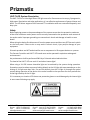
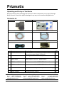
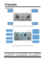
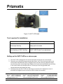
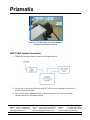
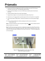
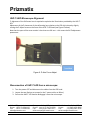
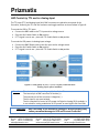
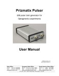
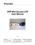
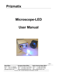
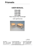
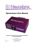
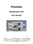
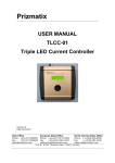
Prizmatix UHP-T-LED User Manual Ver 03 July 2014 Main Office European Sales Office North America Sales Office Phone: +972-72-2500097 Phone: +44-(0)77-9172-9592 Phone: +1-(248)-436-8085 Fax: +972-72-2500096 Fax: +44-(0)20-7681-2977 Fax: +1-(248)-281-5236 [email protected] [email protected] [email protected] P. O .B . 24 4 Gi vat - S h mu el 541 01 , Is r a el Prizmatix UHP-T-LED System Description The UHP-T-LED is an Ultra High Power LED light source for fluorescence microscopy, Optogenetics, High power illumination and other applications. It is an effective replacement of spectral lamps and lasers. The LED driver supports CW or external TTL modulation with user-controlled frequency and duty cycle. Safety Before applying power to the power adaptor of the system ensure that the protective conductor of the three-conductor mains power cord is correctly connected to the protective earth contact of the socket outlet! Improper grounding can cause electric shock and damage to health or even death! When wiring the device first disconnect it from the power source and then turn OFF the main switch on the front panel. Failure to do so may result in electric shock, injury and/or damage of your equipment. Prizmatix products are NOT authorized for use as components in life support devices or systems. The Current Controller and UHP-T-LED heads must not be operated in explosion endangered environments! Any maintenance shall be performed ONLY by a Prizmatix authorized technician. The head of the UHP-T-LED can emit UV and other intense light! When using a UV LED intense ultraviolet light can be emitted by the system during operation. Precautions must be taken to prevent looking directly at the UV light with unprotected eyes or the shining of UV light onto bare skin. Do not look directly into the UV light or through the optical system during operation of the device: this can be harmful to the eyes even for short periods due to the high intensity of the UV light. If it is necessary to view the LED’s beam use protective glasses to avoid damage by the intense light. In some cases following may apply: Main Office European Sales Office North America Sales Office Phone: +972-72-2500097 Phone: +44-(0)77-9172-9592 Phone: +1-(248)-436-8085 Fax: +972-72-2500096 Fax: +44-(0)20-7681-2977 Fax: +1-(248)-281-5236 [email protected] [email protected] [email protected] P. O .B . 24 4 Gi vat - S h mu el 541 01 , Is r a el Prizmatix Unpacking and Set-up of the Device Remove the device from packaging and inspect it for loose components or any signs of damage. Notify Prizmatix if the device appears damaged in any way: do not install a damaged device. Contents List: UHP-T-LED-XXX Head UHP-T-Controller with Keys LED Control Cable LED Current Cable Mains Power Cord Power Adaptor # 1 Item UHP-T-LED-XXX Head 2 UHP-T-LED-Controller Description UHP-T-LED head, with Olympus / Zeiss / Nikon / Leica microscope adaptor (optional) Ultra High Power LED Benchtop Current Controller QTY 1 3 Switch Keys Switch keys for ON/OFF power switch 2 4 LED Control Cable Cable to connect the UHP-T-LED to Controller 1 5 LED Current Cable Cable to connect the UHP-T-LED to Controller 1 6 Mains Power Cord Cord to connect the power adaptor to mains voltage 1 7 Power Adaptor Universal power adaptor 1 1 Main Office European Sales Office North America Sales Office Phone: +972-72-2500097 Phone: +44-(0)77-9172-9592 Phone: +1-(248)-436-8085 Fax: +972-72-2500096 Fax: +44-(0)20-7681-2977 Fax: +1-(248)-281-5236 [email protected] [email protected] [email protected] P. O .B . 24 4 Gi vat - S h mu el 541 01 , Is r a el Prizmatix System overview: System Power Indicator System ON/OFF Key Switch LED Emission Switch LED Output Power Control Figure 1: Front panel of UHP-T-LED Current Controller Figure 2: Rear panel of UHP-T-LED Current Controller Main Office European Sales Office North America Sales Office Phone: +972-72-2500097 Phone: +44-(0)77-9172-9592 Phone: +1-(248)-436-8085 Fax: +972-72-2500096 Fax: +44-(0)20-7681-2977 Fax: +1-(248)-281-5236 [email protected] [email protected] [email protected] P. O .B . 24 4 Gi vat - S h mu el 541 01 , Is r a el Prizmatix Connector for LED Control Cable Connector for LED Control Cable Figure 3: UHP-T-LED Head Tools required for installation: Tool Function Microscope Hex key Lamp port set screws 2mm Hex key or 5/64" Hex Key UHP-T-LED Z-Axis Focus adjustment Setting up the UHP-T-LED on a microscope: 1. The UHP-T-LED is designed to fit into the fluorescence lamp port of a microscope. 2. Dismantle any existing fluorescence lamp (Hg, Xenon, etc.) from the microscope: most microscopes manufacturers (Zeiss, Olympus, Leica) use set screws to tighten the lamp onto the port of the microscope body. Release the screws and carefully pull out the lamp. In the case of Nikon microscopes with an F-mount port turn the grooved collar counterclockwise and release the lamp. 3. Carefully insert the UHP-T-LED into the lamp port. Ensure the Z-adjustment screw is accessible and tighten the set screws (or collar in Nikon microscopes). Main Office European Sales Office North America Sales Office Phone: +972-72-2500097 Phone: +44-(0)77-9172-9592 Phone: +1-(248)-436-8085 Fax: +972-72-2500096 Fax: +44-(0)20-7681-2977 Fax: +1-(248)-281-5236 [email protected] [email protected] [email protected] P. O .B . 24 4 Gi vat - S h mu el 541 01 , Is r a el Prizmatix Figure 4: The lamp port and its set screws (Olympus microscope shown) UHP-T-LED System Connection 1. The general cabling system is shown in the diagram below: 2. Put the Key in the Power Switch of the UHP-T-LED Current Controller and ensure it’s turned to the OFF position. 3. Turn the LED power adjustment dial on the front panel of the Current Controller counterclockwise to the lowest setting. Main Office European Sales Office North America Sales Office Phone: +972-72-2500097 Phone: +44-(0)77-9172-9592 Phone: +1-(248)-436-8085 Fax: +972-72-2500096 Fax: +44-(0)20-7681-2977 Fax: +1-(248)-281-5236 [email protected] [email protected] [email protected] P. O .B . 24 4 Gi vat - S h mu el 541 01 , Is r a el Prizmatix 4. Connect the LED Control Cable and the LED Current Cable to the UHP-T-LED Current Controller and to the UHP-T-LED Head (See Figure 5 below). 5. Connect the Power Adaptor cord to the 12VDC jack on the back panel of the Current Controller. 6. Connect the Mains Power Cord to the Power Adaptor. 7. Plug the Power Adaptor into the wall outlet with the Mains Power Cord. 8. Switch the Int / Ext toggle switchs at the back panel of Current Controller to Int position. 9. Turn the Key Switch to ON position. The small red indicator on the front panel will light ON. 10. Switch to ON the LED Emission Switch and adjust the dial control to the desired output power level. Note: The small red indicator on the front panel will light ON, ONLY if all two cables from LED head to controller are connected. Note: The LED head contains a thermistor to regulate the temperature of the LED and the fan is activated only once the LED begins to warm up. When the LED is switched on from a cold state at the maximum power setting the fan will start to work after 5 - 20 seconds, depending on the wavelength. Figure 5: Cable connections on the rear panel of the UHP-LED-Current-Controller Main Office European Sales Office North America Sales Office Phone: +972-72-2500097 Phone: +44-(0)77-9172-9592 Phone: +1-(248)-436-8085 Fax: +972-72-2500096 Fax: +44-(0)20-7681-2977 Fax: +1-(248)-281-5236 [email protected] [email protected] [email protected] P. O .B . 24 4 Gi vat - S h mu el 541 01 , Is r a el Prizmatix UHP-T-LED Microscope Alignment Z -alignment of the Collimator lens is required to optimize the illumination provided by the UHP-TLED. Adjustment of the Z placement of the collimating lens relative to the LED chip is done by slightly turning the Z-Adjust screw on the faces of the UHP-T-LED head (see Figure 6 below). Note that the span of the screw motion is less than one full turn – this covers the full Z adjustment parameters. Figure 6: Z-Axis Focus Adjust Disconnection of UHP-T-LED from a microscope: 1. Turn the power OFF and disconnect the cables from the LED head. 2. Loosen the two fixation set screws (or the F-mount collar on Nikon). 3. Pull out the UHP-T-LED head to disengage it from the microscope. Main Office European Sales Office North America Sales Office Phone: +972-72-2500097 Phone: +44-(0)77-9172-9592 Phone: +1-(248)-436-8085 Fax: +972-72-2500096 Fax: +44-(0)20-7681-2977 Fax: +1-(248)-281-5236 [email protected] [email protected] [email protected] P. O .B . 24 4 Gi vat - S h mu el 541 01 , Is r a el Prizmatix LED Control by TTL and /or Analog Input The TTL input (TTL) and Analog Input (Ain) BNC connectors are placed at rear panel of the Controller, featuring the TTL and Ain connector and toggle switches as shown below in Figure 8: To control the LED by TTL input: Connect the BNC cable to the TTL input and to voltage source. Place the Ain Enable Switch to Ext position If TTL signal is not in use – place the TTL Enable Switch to Int position To control the LED power via Analog Input voltage: Connect the BNC 50ohm cable to the Ain input and to voltage source. Place the Ain Enable Switch to Ext position If TTL signal is not in use – place the TTL Enable Switch to Int position Figure 8: Rear panel of UHP-T-LED Current Controller with Analog Input option installed Remarks: The absolute maximum voltage applied to Ain is +5V. The internal pin of BNC connector is Positive (+). The external part of the connector is Negative (-). The Ain input is not opto isolated. The Ain intended for control of LED power via Digital to Analog (D/A) modules. It is not suited for analog modulation of LED power at rates higher than few 10Hz Attention: Any overriding of the maximum voltage or inverse polarity may cause permanent damage to LED and Current Controller! Main Office European Sales Office North America Sales Office Phone: +972-72-2500097 Phone: +44-(0)77-9172-9592 Phone: +1-(248)-436-8085 Fax: +972-72-2500096 Fax: +44-(0)20-7681-2977 Fax: +1-(248)-281-5236 [email protected] [email protected] [email protected] P. O .B . 24 4 Gi vat - S h mu el 541 01 , Is r a el