1
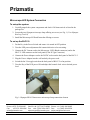
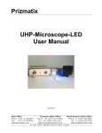
Prizmatix Microscope-LED User Manual Ver.3 Main Office European Sales Office North America Sales Office Phone:+972-72-2500097 Phone:+44 (0)77-9172-9592 Phone: +1-(248)-436-8085 Fax: +972-72-2500096 Fax: +44 (0)20-7681-2977 Fax: +1-(248)-281-5236 [email protected] [email protected] [email protected] P. O .B . 24 4 Gi vat - S h mu el 541 010 2, Is r ael Prizmatix Microscope-LED System Description The Microscope-LED is a High Power LED light source for Olympus microscope BX, IX and SZX series. The High Power LED light source module is an effective replacement of Hg lamps in many applications, such as fluorescence microscopy. The LED driver supports CW or external TTL modulation with user controllable frequency and duty cycle. Package List # 1 Item Microscope-LED 2 3 4 5 6 BLCC-2 Switch Keys DC Current cord ES25A24 Power Cord Description Microscope-LED head equipped with Olympus Microscope adaptor Benchtop High Power LED Current Controller Switch keys for ON/OFF power switch Cord to connect the Microscope-LED to the BLCC-2 Power Adaptor Cord to connect the power adaptor to mains voltage QTY 1 1 2 1 1 1 Microscope-LED versions The Microscope-LEDs are manufactured at several versions according to the preinstalled LED wavelength. Currently available wavelengths are: 365 nm, 385 nm, 390 nm, 395 nm, 400 nm, 405 nm, 410 nm, 415 nm, 420 nm, 425 nm, 430 nm, 435 nm, 440 nm, 445 nm, 455 nm, 460 nm, 470 nm, 480 nm, 495nm, 500 nm, 515 nm, 535 nm, 540 nm, 595 nm, 630 nm and white. Other wavelengths are available by special request. Tools Required: Tool # 1 2 Tool Olympus Hex key 3 mm Hex key QTY 1 2 Used for Lock of the Microscope-LED head to Olympus microscope Remark This Hex key is normally supplied with Olympus microscope XY and Z adjustment (M4 setscrews) Main Office European Sales Office North America Sales Office Phone:+972-72-2500097 Phone:+44 (0)77-9172-9592 Phone: +1-(248)-436-8085 Fax: +972-72-2500096 Fax: +44 (0)20-7681-2977 Fax: +1-(248)-281-5236 [email protected] [email protected] [email protected] P. O .B . 24 4 Gi vat - S h mu el 541 010 2, Is r ael Prizmatix Microscope-LED System Connection To setup the system: 1. Carefully unpack the system components and check if all items arrived as listed in the package list. 2. Loosen the two Olympus microscope lamp affixing set screws (see Fig. 1). Use Olympus Hex key (Tool #1) 3. Install the Microscope-LED and fasten the affixing set screws. To set up the BLCC-2: 1. Put the Key in the Power Switch and ensure it is turned in OFF position 2. Turn the LED power adjustment dial counterclockwise to lowest setting. 3. Connect the DC Current cord to the Microscope –LED (Binder connector) and to the BLCC-2 LED connector on the back panel (9-Pin D-Type Connector). 4. Connect the Power Adaptor cord to the 24VDC socket on the back panel of the BLCC-2 5. Plug the Power Adaptor into the wall outlet by the power cord. 6. Switch the Int / Ext toggle switch on the back panel of BLCC-2 to Int position. 7. Turn the Key of the LED power ON and adjust dial control clock wise to desired power level. Fig. 1: Olympus BX-61 fluorescence microscope lamp connection element Main Office European Sales Office North America Sales Office Phone:+972-72-2500097 Phone:+44 (0)77-9172-9592 Phone: +1-(248)-436-8085 Fax: +972-72-2500096 Fax: +44 (0)20-7681-2977 Fax: +1-(248)-281-5236 [email protected] [email protected] [email protected] P. O .B . 24 4 Gi vat - S h mu el 541 010 2, Is r ael Prizmatix Microscope-LED - Microscope Alignment XY adjustment is sometimes required due to slight misalignment of the optical path of the Microscope-LED relative to the microscope optical path. Z -alignment of the collector lens is required to optimize the excitation power and the illumination provided by the Microscope-LED. XY adjustment Align the LED with a small movement (few mm in each direction) of the internal LED assembly relative to the Microscope-LED output lens. The procedure should be performed when the Microscope-LED head is connected to the microscope body. Adjust the X and Y placement of the LED assembly by slightly turning the respective XY adjustment screws (M4 Allen screws see Fig. 2) as follows: (a) Turn ON the Microscope-LED at less than maximum power. (b) Engage appropriate filter set and one of the objectives and then observe the light coming out of the objective by placing a piece of carton paper at the place of the sample slide. Fig. 2: Microscope-LED XY adjustment set screws and Z adjustment fine screw. Main Office European Sales Office North America Sales Office Phone:+972-72-2500097 Phone:+44 (0)77-9172-9592 Phone: +1-(248)-436-8085 Fax: +972-72-2500096 Fax: +44 (0)20-7681-2977 Fax: +1-(248)-281-5236 [email protected] [email protected] [email protected] P. O .B . 24 4 Gi vat - S h mu el 541 010 2, Is r ael Prizmatix (c) Slightly release all 4 screws by about ¼ turn. Use 3 mm Allen screw driver (tool #2). (d) Use two 3 mm Allen screw drivers on opposite sides of the Microscope-LED head block (tool #2). The screwdrivers should be turned in opposite directions (on one side screw inwards, while at other side unscrew the setscrews) in order to move the internal LED assembly relative to the lens. (e) Observe the spot of light on the carton paper while turning the setscrews until optimal position is obtained. (f) After reaching optimal position in both X and Y directions tighten all screws. Remark: Do not apply extensive force on the screws. Z Adjustment Adjust the Z placement of the collimating lens relatively to the LED chip by slightly turning the ZAdjust screw on one of the faces of the Microscope-LED head. Disconnection of Microscope-LED from the system 1. Untighten the two fixation screws (use tool #1). 2. Pull out the Microscope-LED to disengage it from the Microscope system. Main Office European Sales Office North America Sales Office Phone:+972-72-2500097 Phone:+44 (0)77-9172-9592 Phone: +1-(248)-436-8085 Fax: +972-72-2500096 Fax: +44 (0)20-7681-2977 Fax: +1-(248)-281-5236 [email protected] [email protected] [email protected] P. O .B . 24 4 Gi vat - S h mu el 541 010 2, Is r ael