1
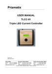
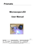
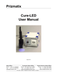
Prizmatix USER MANUAL FC2-LED FC3-LED FC5-LED FC7-LED Fiber Coupled Multi Wavelength LED Light Sources Version: 1.2 Date: 9.02.2014 Main Office Phone: +972-72-2500097 Fax: +972-72-2500096 [email protected] European Sales Office North America Sales Office Phone: +44 (0)77-9172-9592 Phone: +1-(248)-436-8085 Fax: +44 (0)20-7681-2977 Fax: +1-(248)-281-5236 [email protected] [email protected] P.O.B. 244 Givat-Shmuel 5410102, Israel Prizmatix Table of Contents 1 Introduction ................................................................................................................... 3 1.1 Features ............................................................................................................................ 3 1.2 Specifications .................................................................................................................... 3 2 Overview ........................................................................................................................ 4 3 Safety ............................................................................................................................. 5 4 Operating the FC3-LED .................................................................................................... 6 4.1 Initial power up and system test ...................................................................................... 6 4.2 LED power switching by TTL signal ................................................................................... 8 4.2.1 4.3 TTL control usage..................................................................................................... 8 LED Power Control by Analog Input (Optional Feature) ................................................10 4.3.1 General Information regarding Analog modulation .............................................. 10 4.3.2 Analog Modulation setup ...................................................................................... 11 4.4 LED Power Control by USB Computer interface (Optional Feature) ..............................13 Main Office Phone: +972-72-2500097 Fax: +972-72-2500096 [email protected] European Sales Office North America Sales Office Phone: +44 (0)77-9172-9592 Phone: +1-(248)-436-8085 Fax: +44 (0)20-7681-2977 Fax: +1-(248)-281-5236 [email protected] [email protected] P.O.B. 244 Givat-Shmuel 5410102, Israel Prizmatix 1 Introduction The FC3-LED is designed to provide multiple wavelength excitation fiber-coupled light sources for various photonics applications. The current controller provides low noise current for driving the high power LEDs in continuous (CW) or chopped operation mode via external TTL input. Analog modulation mode and USB computer control are optional Remark: This User Manual refers to FC3-LED. However, unlessstated explicitly information provided here is relevant to all versions / variations of the device. 1.1 Features Several independent high power LEDs and LED drivers Constant current or chopping operation modes Precise control over LED current setting by the use of 10-turn potentiometer with dial TTL external trigger input Analog modulation input - optional Computer control through USB - optional 1.2 Specifications Wavelengths: Any combination from the available range of high power LEDs TTL modulation frequency: DC – 10 KHz Analog Modulation frequency (optional): DC-10 KHz Connectors for TTL input: BNC Connectors for analog modulation input: BNC Input power supply: 24 VDC, 1A Power adaptor input: 100-240 VAC, 1A, 47-63Hz Dimensions: FC2-LED: FC3-LED: FC5-LED: FC7-LED: 174mm x 130mm x 197mm (W x H x D) without extrusions. 174mm x 130mm x 197mm (W x H x D) without extrusions. 241mm x 130mm x 197mm (W x H x D) without extrusions. 300mm x 130mm x 250mm (W x H x D) without extrusions. Power adaptor: 52mm x 35mm x 90mm (W x H x L) Specifications are subject to change without notice. Main Office Phone: +972-72-2500097 Fax: +972-72-2500096 [email protected] European Sales Office North America Sales Office Phone: +44 (0)77-9172-9592 Phone: +1-(248)-436-8085 Fax: +44 (0)20-7681-2977 Fax: +1-(248)-281-5236 [email protected] [email protected] P.O.B. 244 Givat-Shmuel 5410102, Israel Prizmatix 2 Overview Fig. 1: Front Panel controls of FC3-LED Fig. 2: Back panel controls of FC3-LED Main Office Phone: +972-72-2500097 Fax: +972-72-2500096 [email protected] European Sales Office North America Sales Office Phone: +44 (0)77-9172-9592 Phone: +1-(248)-436-8085 Fax: +44 (0)20-7681-2977 Fax: +1-(248)-281-5236 [email protected] [email protected] P.O.B. 244 Givat-Shmuel 5410102, Israel Prizmatix 3 Safety Before supplying electricity to the power adaptor of the FC3-LED system, make sure that the protective conductor of the 3-conductor mains power cord is correctly connected to the protective earth contact of the socket outlet! Improper grounding can cause electric shock with damage to your health or even death! When wiring the device disconnect it from the power source and turn the main switch to Off on the back panel of the FC3-LED. Not doing so may result in electric shock, injury and/or damage of your equipment. Prizmatix products are NOT authorized for use as components in life support devices or systems. The FC3-LED must not be operated in explosion endangered environments! Any maintenance shall be performed ONLY by Prizmatix authorized technician. Cellular phones or other radio transmitters are not to be used within the range of few meters of this unit. The FC3-LED can emit an UV and other intense light! In cases where a UV LED is part of the FC3-LED system intense UV light can be emitted by the system during operation. Precautions must be taken to prevent looking directly at the UV light with unprotected eyes or illuminating the UV light on skin. Do not look directly into the UV light or look through the optical system during operation of the device. This can be harmful to the eyes even for brief periods due to the high intensity of the UV light. If viewing of the light is necessary use light protective glasses to avoid damage by the intense light. Main Office Phone: +972-72-2500097 Fax: +972-72-2500096 [email protected] European Sales Office North America Sales Office Phone: +44 (0)77-9172-9592 Phone: +1-(248)-436-8085 Fax: +44 (0)20-7681-2977 Fax: +1-(248)-281-5236 [email protected] [email protected] P.O.B. 244 Givat-Shmuel 5410102, Israel Prizmatix 4 Operating the FC3-LED 4.1 Initial power up and system test Connect the power adaptor to the FC3-LED. Switch ON the system by the ON/OFF toggle switch on the back panel of the device. Change all the Int / Ext toggle switches to Int position. In this position the LED power will be controlled by the front panel dial. Connect the optical fiber to the Fiber Output connector on the front panel. Ideally the optical fiber will have a core of at least 1000micron. Connect the distal end of the fiber to a power meter. Turn counter-clockwise all potentiometer dials to zero with the exception of the one to be tested. Turn clockwise the desired dial to get maximum power of the channel. If using a laser power meter for the reading, select appropriate wavelength at the power meter settings. Fig. 3: Connection of FC3-LED for power measurement. Remark: When using Laser Power Meter for FC3-LED power measurement only a single LED should be tested at a time. During the measurement all other LEDs should be turned to OFF state. In order to measure the spectrum of one of the LEDs it is preferable to use an additional thin fiber patch cord, and to connect this fiber between the spectrometer and the fiber connected to the FC3-LED, as shown at the following figure. Main Office Phone: +972-72-2500097 Fax: +972-72-2500096 [email protected] European Sales Office North America Sales Office Phone: +44 (0)77-9172-9592 Phone: +1-(248)-436-8085 Fax: +44 (0)20-7681-2977 Fax: +1-(248)-281-5236 [email protected] [email protected] P.O.B. 244 Givat-Shmuel 5410102, Israel Prizmatix Fig. 4: Connection of FC3-LED for LED spectrum measurement. In the case of a spectrum measurement, all 3 LEDs may be measured at once by utilizing a Y-shaped bundle unless no significant overlap between the LED emission bands exists. Tip: Use the fastest data acquisition time of the spectrometer to prevent detector saturation. Remark: In some spectrometers due to unsuppressed second order dispersion you may notice additional virtual peaks at x2 wavelength. For example, while measuring LED peaking at 400nm smaller peak at 800nm may be noticed. These are NOT real emission peak but measurement artifact. Main Office Phone: +972-72-2500097 Fax: +972-72-2500096 [email protected] European Sales Office North America Sales Office Phone: +44 (0)77-9172-9592 Phone: +1-(248)-436-8085 Fax: +44 (0)20-7681-2977 Fax: +1-(248)-281-5236 [email protected] [email protected] P.O.B. 244 Givat-Shmuel 5410102, Israel Prizmatix 4.2 LED power switching by TTL signal The TTL input provides simple way to control the LED state. The TTL input connector is on the back panel of the FC3-LED device. The TTL High signal will turn the LED ON, while TTL Low signal will turn the LED OFF. The LED power during ON will be set by the potentiometer on the front panel. 4.2.1 TTL control usage Connect the TTL signal by using a cable with BNC connector to the required channel. Place the Int / Ext toggle switch at Ext position for enabling the TTL. See following figures for examples of TTL usage. Fig. 5: FC3-LED connection for chopped operation measurement Main Office Phone: +972-72-2500097 Fax: +972-72-2500096 [email protected] European Sales Office North America Sales Office Phone: +44 (0)77-9172-9592 Phone: +1-(248)-436-8085 Fax: +44 (0)20-7681-2977 Fax: +1-(248)-281-5236 [email protected] [email protected] P.O.B. 244 Givat-Shmuel 5410102, Israel Prizmatix Fig. 6: FC3-LED connection for synchronized chopping LED operation and spectrometer data acquisition. Fig. 7: FC3-LED connected for synchronized detection by Lock-in amplifier. Main Office Phone: +972-72-2500097 Fax: +972-72-2500096 [email protected] European Sales Office North America Sales Office Phone: +44 (0)77-9172-9592 Phone: +1-(248)-436-8085 Fax: +44 (0)20-7681-2977 Fax: +1-(248)-281-5236 [email protected] [email protected] P.O.B. 244 Givat-Shmuel 5410102, Israel Prizmatix 4.3 LED Power Control by Analog Input (Optional Feature) If the LED output power needs to be controlled smoothly over the whole power range from minimum to maximum power the Analog input is a preferable choice. 4.3.1 General Information regarding Analog modulation In order to implement the Analog input control a few basic issues shall be clarified: Transfer Function – describes the output LED power as function of Analog input voltage. The transfer function will be slightly different for each LED type but in general it will be similar to the following figure: Fig. 8: LED Output Power vs. current control Voltage input at Vin BNC connector on back panel. We can see from the graph that the input values 0V to 1.5V and 3.75V to 5V do not contribute any changes to the output power. The Output power is an inverse function of the input voltage between 1.5V to 3.75V. Amplitude Modulation (AM) – AM is the varying of strength of the transmitted signal in relation to the information being sent. In this case it is a varying of the LED amplitude according to the input voltage values. In order to get good AM modulation it is very important to supply the correct input modulation voltage (Pk-Pk) and the correct offset voltage, as described in following figure. Main Office Phone: +972-72-2500097 Fax: +972-72-2500096 [email protected] European Sales Office North America Sales Office Phone: +44 (0)77-9172-9592 Phone: +1-(248)-436-8085 Fax: +44 (0)20-7681-2977 Fax: +1-(248)-281-5236 [email protected] [email protected] P.O.B. 244 Givat-Shmuel 5410102, Israel Prizmatix Fig. 9: Analog modulation basics; Green labels refer to the Ain signal, Blue labels refer to the output light. If the input signal and the offset are of appropriate magnitude, and the modulation frequency is within allowed range the quality of the LED, modulation can be checked by a Lissajous curve such as the figure below. More information on Lissajous curves can be found at: http://en.wikipedia.org/wiki/Lissajous_curve Fig. 10: FC3-LED Lissajous of Analog modulated LED 4.3.2 Analog Modulation setup 4.3.2.1 Preparation of the Analog Source Main Office Phone: +972-72-2500097 Fax: +972-72-2500096 [email protected] European Sales Office North America Sales Office Phone: +44 (0)77-9172-9592 Phone: +1-(248)-436-8085 Fax: +44 (0)20-7681-2977 Fax: +1-(248)-281-5236 [email protected] [email protected] P.O.B. 244 Givat-Shmuel 5410102, Israel Prizmatix Connect the Analog voltage source (oscillator, function generator, D/A card) to Channel #1 of the oscilloscope. Adjust the Peak-Peak amplitude of the Analog voltage source to about 1.0V. Adjust the Offset Voltage of the Analog voltage source to about 2.5V. Fig. 11: Setup for analog modulation test of one of channels of FC3-LED. Main Office Phone: +972-72-2500097 Fax: +972-72-2500096 [email protected] European Sales Office North America Sales Office Phone: +44 (0)77-9172-9592 Phone: +1-(248)-436-8085 Fax: +44 (0)20-7681-2977 Fax: +1-(248)-281-5236 [email protected] [email protected] P.O.B. 244 Givat-Shmuel 5410102, Israel Prizmatix 4.3.2.2 Preparation of the FC3-LED Turn all potentiometers counter-clockwise to the minimum power position. Connect the Output optical connector to a photodiode receiver by an optical fiber.Ideally the fiber will be >1000micron core diameter. Connect the Photodiode Receiver output to Channel #2 of the oscilloscope. Connect the Analog signal cable to one of the Ain input connectors on the back panel of the FC3-LED. Switch ON the ON/OFF switch of the FC3-LED, located at back panel. Change the position of the toggle switch Int/Ext to the Ext position. Observe the Analog input signal and the photodiode signal on the oscilloscope. Adjust the Time Base and the Volt/Div of the oscilloscope for optimal observation of signals. Adjust the Offset Voltage and the Peak-Peak voltage of the input analog signal to obtain the best analog modulation working conditions. If the photodiode signal appears truncated or highly deformed reduce the Peak-Peak voltage of the analog source, readjust the Offset Voltage and then try to increase the Peak-Peak amplitude of the source once again. 4.4 LED Power Control by USB Computer interface (Optional Feature) The FC3-LED system may include microprocessor based USB computer control card and PC software. The PC software developed on LabView platform. Both stand alone application EXE file for running the software independent of LabView development system and LabView VI is supplied for advanced users interested in changing and expansion of the existing application. For instruction on USB computer interface, installation of drivers, usage of the software and LabView VI code, please refer to the User Manual of TLCC-01 LED Current Controller. Main Office Phone: +972-72-2500097 Fax: +972-72-2500096 [email protected] European Sales Office North America Sales Office Phone: +44 (0)77-9172-9592 Phone: +1-(248)-436-8085 Fax: +44 (0)20-7681-2977 Fax: +1-(248)-281-5236 [email protected] [email protected] P.O.B. 244 Givat-Shmuel 5410102, Israel