1
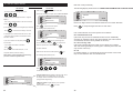
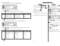
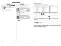
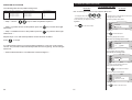
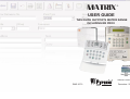
MATRIX
®
USER GUIDE
THIS GUIDE SUPPORTS MATRIX RANGE
INCLUDING MX PROX
R
R
RINS 367-3
Software version I.8
December 2001
Pyronix Limited
Pyronix House
Braithwell Way
Hellaby, Rotherham
S66 8QY, ENGLAND
Tel: +44 (0) 1709 700100
Fax: +44 (0) 1709 533429
Technical help line (UK only): 0900 8037 800
This is a premium rate line where calls are charged at 50p per minute
U [email protected]
[email protected]
[email protected]
[email protected]
website: www.pyronix.com
email:
CONTENTS
1.
GENERAL FEATURES
2.
KEYPAD LAYOUT
3.
KEYPAD INDICATIONS
4.
4.1
4.2
4.3
4.4
4.5
GENERAL OVERVIEW OF KEYPAD DISPLAYS
Partition Indications
Arm modes
Displaying system faults
Displaying open zones
Displaying open zones
5.
5.1
5.1.1
5.1.2
5.2
5.2.1
5.2.2
5.3
5.3.1
5.3.2
ARMED / DISARMED MODES USING LED KEYPAD
Arming a single partition with keypad allocated to this partition.
Arming when the option “Display open zones” is enabled by the engineer.
Arming when the option “Display open zones in disarm” is disabled by the engineer.
Displaying the status of the system when the partition is armed.
Common display
Private mode
Disarming single partition with keypad allocated to the partition
Disarming the system in normal mode.
Disarming the system after alarm condition when
“Display zones in alarm” is disabled by the engineer
Disarming the system after alarm condition when
“Display open zones in alarm” is enabled by the engineer
Arming the system from keypad in multiple partitions
Arming when the option “Display open zones in day” is enabled by the engineer
Arming when the option “Display open zones in disarm” is disabled by the engineer
Displaying the status of the system when the partition is armed.
Common display
Private mode
Disarming the panel in multiple partition
Disarming the system in normal mode
Disarming the system after alarm condition when
“Display zones in alarm” disabled by the engineer
Disarming the system after alarm condition when
“Display open zones in alarm” is enabled by the engineer.
5.3.3
5.4
5.4.1
5.4.2
5.5
5.5.1
5.5.2
5.6
5.6.1
5.6.2
5.6.3
6.
6.1
6.1.1
6.1.2
6.2
6.2.1
6.2.2
6.3
6.3.1
6.3.2
6.3.3
6.4
6.4.1
6.4.2
6.5
6.5.1
6.5.2
6.6
6.6.1
6.6.2
6.6.3
6.7
6.8
6.10
ARMED / DISARMED MODES USING LCD KEYPAD
Arming a single partition with keypad allocated to this partition.
Arming when the option “Display open zones” is enabled by the engineer.
Arming when the option “Display open zones in disarm” is disabled by the engineer.
Displaying the status of the system when the partition is armed.
Common display
Private mode
Disarming single partition with keypad allocated to the partition
Disarming the system in normal mode.
Disarming the system after alarm condition when
“Display zones in alarm” is disabled by the engineer
Disarming the system after alarm condition when
“Display open zones in alarm” is enabled by the engineer
Arming the system from keypad in multiple partitions
Arming when the option “Display open zones in day” is enabled by the engineer
Arming when the option “Display open zones in disarm” is disabled by the engineer
Displaying the status of the system when the partition is armed.
Common display
Private mode
Disarming the panel in multiple partition
Disarming the system in normal mode
Disarming the system after alarm condition when
“Display zones in alarm” disabled by the engineer
Disarming the system after alarm condition when
“Display open zones in alarm” is enabled by the engineer.
Golden rules for partitions
Display open zones
Fault tones
1
7.
7.1
7.2
7.3
FUNCTIONS AVAILABLE FROM ALL MODES
Activating Fire alarm
Activating Personal attack
Activating Medical alarm8.
8.
8.1
8.2
USER MODE
Entering User mode
Exiting User mode
9.
9.1
9.2
9.3
9.4
9.5
LIMITED USER MODE
Omitting zones
Displaying event log memory
Setting the volume
Setting the back-light
View time and date
10.
10.1
10.2
10.3
10.4
10.5
10.6
10.6.1
10.7
10.8
10.9
10.10
MASTER USER OPTIONS
Change the time
Changing the date
Changing user codes and allocating user code attributes - LED KEYPAD
Edit user - LCD keypad
Change user codes - LCD keypad
Edit user name - LCD keypad
Temporary language setting
Adjusting the proximity volume
Adding or removing proximity cards
Activating PGM from keypad
Upload / Download one hour window
11.
11.1
MATRIX PROGRAMMABLE ZONE TYPES
Programmable zone types continued
12.
12.1
ZONE PARTITION INDICATION TABLE
Zone table part 2
13
13.1
13.2
13.2.1
13.2.2
13.2.3
13.2.4
13.3
13.3.1
13.3.2
13.3.3
13.3.4
13.4
PROXIMITY READER (MX PROX)
MX PROX Functionality (Normal mode)
Using MX PCARD allocated to one partition.
Arm mode A
Arm mode B
Arm mode C
Arm mode D
Using MX PCARD allocated to multiple partitions.
Partition 1
Partition 2
Partition 3
Partition 4
Alarm condition
14
LED LOG TABLE
15
LCD LOG TABLE
2
PRESS
OR
TO SCROLL THROUGH
ALARM TYPES
PRESS THE
LCD BOTTOM LINE
KEY TO VIEW ZONE NUMBER / USER CODE AND MEANING
LCD TOP LINE
EXPLANATION
OPEN / CLOSE
User name
Armed
01 - 32 A
Armed
01 - 32 B
User name
Armed in mode B by user, number signifies code used
Armed
01 - 32 C
User name
Armed in mode C by user, number signifies code used
Armed in mode D by user, number signifies code used
Armed in mode A by user, number signifies code used
Armed
01 - 32 D
User name
Disarmed
01 - 32
User name
Unset by user, number signifies code used
Inactivity Arm
01 - 32
X
Armed due to inactivity timer
Arm depend
X
X
Armed due to dependency on other partitions
Disarm depend
01 - 32
X
Disarmed due to dependancy on other partitions
UC after alarm
01 - 32
User name
User code after alarm - number signifies user
Bell time end
X
X
Bell time expired
Power on
X
X
Panel powered up
RESTORE
SYSTEM EVENTS
Engineer end
X
X
Engineer mode exited
Engineer Start
X
X
Engineer mode entered
X
X
Walk test entered
Walk test enter
Walk test end
X
X
Walk test exited
Log cleared
X
X
Log cleared
NVM reset to factory defaults
NVM reset
X
X
Time & Date
01 - 32
User name
Time and date changed, number signifies code used
Device found
01 - 64
X
Remote device found on bus - number refers to type / ID
Device lost
01 - 64
X
Remote device found on bus - number refers to type / ID
Bell fuse fail
X (restore)
X
Bell fuse fail / (restore)
Aux fuse fail
X (restore)
X
Auxiliary fuse fail / (restore)
Battery missing
X (restore)
X
Battery missing / (restore)
SYSTEM FAULTS
Battery low
X (restore)
X
Battery low voltage / (restore)
Mains fail
X (restore)
X
Mains fail / (restore)
Telephone fail
X (restore)
X
Telephone line fail / (restore)
Device fail
X (restore)
X
Remote device has gone missing / found on bus
Fail to report
X (restore)
X
Failed to report to central station / (restore)
55
15 LCD LOG TABLE
PRESS
OR
TO SCROLL THROUGH
ALARM TYPES
PRESS THE
1. GENERAL FEATURES
KEY TO VIEW ZONE NUMBER / USER CODE AND MEANING
LCD BOTTOM LINE
LCD TOP LINE
EXPLANATION
Entry Exit
X
X
Entry / Exit time expired
Personal Attack
Zone number
X
PA zone activated, number signifies zone, 00 = keypad
Fire alarm
Zone number
X
PA zone activated, number signifies zone, 00 = keypad
Alarm
Zone number
Zone name
Burglary on zone, number signifies zone
Zone tamper
Zone number
Zone name
Tamper on zone, number signifies zone
Medical alarm
Zone number
X
Medical alarm number signifies zone, 00 = keypad
Tamper
01
X
Global tamper loop broken
Bell tamper loop broken
Tamper
02
X
Tamper
03
X
Zone expander board not present
Tamper
04
X
Fire detector tamper
Tamper
05
X
Remote device missing caused tamper
Tamper
06
X
Key press tamper
Tamper
08
X
Key press tamper
Tamper
09
X
A remote device has transmitted a tamper
Line fail alarm
X
X
Telephone line fail alarm
Omit zone
01 - 32
Zone name
Zone omitted, number signifies zone
Device tamper
XX 01 - 99
XX = device number
Remote device auxiliary tamper
PA restore
Zone number
User name
Personal attack restore
Zone restore
Zone number
User name
Zone restore
Fire restore
Zone number
User name
Fire restore
GT restore
Zone number
User name
Global tamper restore
Alarm restore
Zone number
User name
Alarm restore
Medical restore
Zone number
Medical restore
Medical restore
UP / DOWN LOADING EVENTS
54
Panel ans tel.
X
X
Panel answered the telephone
Panel hug tel
X
X
Panel hung up the telephone line
Full upload
X
X
Full data download from panel
Full download
X
X
Partial upload to panel
Partial upload
X
X
Upload data to panel complete
Upload complete
X
X
Upload data to panel complete
Down load
X
X
Download data from panel complete
Bad UDL code
X
X
Incorrect UDL code
X
UDL code OK
X
Time and date
X
LC expected
X
X
Local connection exspected
PC Arm - Disarm
X
X
PC armed or disarmed the panel
Thank you for buying the Matrix control panel, which uses the latest technology in design and
manufacture. As the end user of the Matrix this manual has been written to help you use the
functions of your alarm system, enabling you to get the best out of the Matrix panel.
Once you are familiar with the panel and its functions it is advisable
to change the factory set Master User code.
The system can be operated in the following modes from which different options are available
to the end user:
1. FUNCTIONS AVAILABLE IN DISARMED MODE
- Arming the panel in (Single partition).
- Arming the panel in (Multiple partitions).
2. FUNCTIONS AVAILABLE IN ARMED MODE
- Disarming the panel in (Single partition).
- Disarming the panel in (Multiple partitions).
3. FUNCTIONS AVAILABLE IN ALARM MODE
- Alarm in Single partition.
- Alarm in Multiple partitions.
4. FUNCTIONS AVAILABLE FROM ALL MODES
- Options available in all modes.
5. FUNCTIONS AVAILABLE IN USER MODE
- All user options are available from the user mode.
5.1 FUNCTIONS AVAILABLE IN LIMITED USER MODE
- Allows arming / disarming the panel, viewing of the event memory log, and setting
the brightness / volume of the keypad.
5.2 FUNCTIONS AVAILABLE IN MASTER USER MODE
- Gives access to all limited user functions as well as changing user codes and clock
settings.
UDL code accepted
Time and date changed by PC
3
2. KEYPAD LAYOUT
LED KEYPAD
1
!
OK
1
A
88
3
2
B
5
6
9
0
LCD KEYPAD
PRESS
OR
TO SCROLL THROUGH
ALARM TYPES
PRESS
OR
AGAIN FOR ZONE
NUMBER / USER CODE
ALARM TYPE MEANINGS
LED
INDICATION
OPEN / CLOSE
2
((
))
A
01 - 32
Armed in mode A by user, number signifies code used
None
B
01 - 32
Armed in mode B by user, number signifies code used
None
C
01 - 32
Armed in mode C by user, number signifies code used
None
D
01 - 32
Armed in mode D by user, number signifies code used
None
U
01 - 32
Disarmed by user, number signifies code used
None
At
X
Armed due to inactivity timer
None
4
3
C
7
4
D
8
AP
X
Armed due to dependency on other partitions
None
UP
X
Disarmed due to dependency on other partitions
None
RESTORE
r1
01 - 32
User code after alarm - number signifies user
None
r2
X
Bell time expired
None
EO
X
Bell time expired
None
E1
X
Engineer mode entered
None
1
Walk test entered
None
SYSTEM EVENTS
BUTTON MEANINGS
1
88
3
2
4
BUTTON MEANINGS
Seven segment display
Shows zone numbers, partitions armed, system
faults, and event memory log number.
Personal Attack
Holding this button down for 2 seconds triggers
an immediate Personal Attack alarm
Personal Attack Alarm
Holding this button down for 2 seconds triggers
an immediate PA alarm.
Fire alarm
Holding this button down for 2 seconds triggers
an immediate Fire alarm
td
6
0
4
Fire Alarm
Holding this button down for 2 seconds triggers
an immediate Fire alarm.
Medical Button
Holding the medical button down for 2 seconds
will trigger an emergency alarm.
Numerical buttons
Functional buttons used for imputing user codes
and user programming.
Arm Button
Used to change arm mode during final exit display.
LED icon Display
Flashing LED’S on / off the status of the system
in different modes.
Function Button
Used for selecting options and confirming actions.
Arm button
Used to change arm mode during exit delay.
Menu Button
Used to enter and exit menu mode
Function button
Used to enter / exit user mode and, save
programming options.
Directional Buttons
Direction buttons
Direction keys are used to select options
and view the log.
Scrolls down menu options and functions
Medical button
Holding the medical button down for 2 seconds
will trigger an emergency alarm.
2
Walk test exited
None
3
Log cleared
None
4
NVM Reset to factory defaults
None
01 - 32
Time & date changes by user, number signifies code used
None
??
01 - 64
Remote device found on bus - number refers to type / ID
None
?
01 - 64
Remote device lost on bus - number refers to type / ID
None
1
Bell fuse fail / (restore)
None
SYSTEM FAULTS
O(r)
O(r)
2
Auxiliary fuse fail / (restore)
None
O(r)
3
Battery missing / (restore)
None
O(r)
4
Battery low voltage / (restore)
None
O(r)
5
Mains fail / (restore)
None
O(r)
6
Telephone line fail / (restore)
None
O(r)
7
Remote device has gone missing / been found on bus
None
O(r)
8
Failed to report to central station
None
Scrolls up menu options and functions
Scrolls to the right in some menu functions
Scrolls to the left in some menu functions
53
14 LED LOG TABLE
PRESS
OR
TO SCROLL THROUGH
ALARM TYPES
PRESS
OR
AGAIN FOR ZONE
NUMBER / USER CODE
3. KEYPAD INDICATIONS
LED KEYPAD
ALARM TYPE MEANINGS
X
Entry / Exit time expired
Alarm
00 - 32
X
PA zone activated, number signifies zone, 00 = keypad
PA Flashing
00 - 32
X
Fire activated, number signifies zone, 00 = keypad
FIRE Flashing
01 - 32
X
Burglary on zone, number signifies zone
Alarm Flashing
01 - 32
X
Tamper on zone, number signifies zone
Tamper Flashing
EE
FAULT
ARMED
SUPPLY
1
00 - 32
LCD KEYPAD
LED
INDICATION
X
Medical alarm number signifies zone, 00 = keypad
None
.t
01
Global tamper loop broken
Tamper
.t
02
Bell tamper loop broken
Tamper
.t
03
Zone expander board not present
Tamper
.t
04
Fire detector tamper
Tamper
.t
05
Remote device missing caused tamper
Tamper
.t
06
Key press tamper
Tamper
!
OK
88
3
FIRE
ALARM
SUPPLY
2
((
))
00:01 mon 01 jan
4
FAULT
DISARMED
READY
READY
PA
TAMPER
No AC power supply to panel.
09
A remote device has triggered a tamper
Tamper
X
Telephone line fail alarm
Line fail alarm
O
01 - 32
Zone omitted, number signifies zone
Omit zone
.rt
01 - 99
Remote device auxiliary tamper
Device tamper
.t
L
Indicates a system fault.
Personal attack restore
PA steady
Zone restore
Alarm steady
01 - 32
X
Fire restore
Fire steady
01 - 32
X
Global tamper restore
Tamper steady
System armed.
.
Indicates
the panel is in disarmed mode.
Alarm restore
Alarm steady
Medical restore
None
Engineers mode is active.
Engineers mode is active.
UP / DOWN LOADING EVENTS
PC
00
Panel answered the telephone
None
PC
01
Panel hung up the telephone line
None
PC
02
Full data down load from panel
None
PC
03
Partial upload to panel
None
PC
04
Upload data to panel complete
None
PC
05
Upload data to panel complete
None
PC
06
Download data from panel complete
None
PC
07
Incorrect UDL code
None
No fault on panel.
Indicates a system fault.
X
X
Battery fault.
No fault on panel.
!
X
X
Indicates AC / DC power
. supply to panel.
Battery fault
01 - 32
01 - 32
No AC power supply to panel.
Indicates AC / DC power supply to panel.
01 - 32
01 - 32
MATRIX
OK
OK
OK
Open one or more zones.
Indicates the panel is in user mode.
All zones are closed and panel is ready
to be armed.
Open one or more zones.
Flashing ready light indicates the
programming function is active.
All zones are closed and panel is ready
to be armed.
Flashing ready light indicates the
programming function is active.
When the panel is in fire alarm the LED
will be On and a zone number indicating
the zone activated will be displayed on
the 7 segment display.
Indicates the panel is disarmed.
52
PC
08
UDL code accepted
None
PC
09
Time / Date changed by PC
None
PC
10
Local connection expected
None
PC
11
PC Armed / Disarmed the panel
None
Indicates the panel is armed.
((
5
))
When Alarm is activated the LED will
flash and a zone number indicating the
zone activated will be displayed on the
7 segment display.
When a PA is activated the LED will be
On and a zone number indicating the zone
activated will be displayed on the 7
segment display.
When Tamper alarm is activated the
LED will be On and a zone number
indicating the zone activated will be
displayed on the 7 segment display.
4. GENERAL OVERVIEW OF THE kEYPAD DISPLAY
13.4 Alarm condition
4.1 PARTITION INDICATIONS
LCD KEYPAD
LED KEYPAD
1
2
3
4
88
There are two 7 segment displays
on the LED keypad, which will
display all programming information,
including - arming and disarming of
the panel, zones activated, event
memory log and system faults.
The following status will be displayed for each partition of
a common keypad.
When an alarm is activated by the control panel the MX PROX reader will emit an alarm tone
and status LED 1 will illuminate.
= Alarm Condition
= Armed
= Arming
1
!
OK
88
3
2
((
))
All partitions are disarmed =
4
Disarming after an alarm.
Partition 1
PARTITION 1 2 3 4
STATUS
Partition 2
OK
If an alarm occured in a partition after disarm the status LED will flash rapidly.
To clear the display and return to disarmed mode repeat the disarm procedure again.
MATRIX
Partition 1 is arming =
SYSTEM BUSY
Partition 3
Partition 4
PARTITION 1 2 3 4
STATUS
4.1 PARTITION INDICATIONS DISPLAYED ON THE 7
SEGMENT DISPLAY.
If a keypad is allocated as a common keypad for arming /
disarming all partitions, The partition status will be
displayed on the keypad
OK
MATRIX
Partition 1 is armed =
Segments On / Off indicate:
1
2
3
4
88
Segments Off = PARTITION 1 IS DISARMED
1
2
3
4
88
PARTITION 1 2 3 4
STATUS
OK
MATRIX
Partition 1 in alarm condition =
Segments flashing = PARTITION 1 ARMING
1
2
3
4
88
PARTITION 1 2 3 4
STATUS
OK
MATRIX
Segments On = PARTITION 1 IS ARMED
1
2
3
4
88
Segments flashing very fast =
PARTITION 1 IN ALARM CONDITION
6
51
4.2 ARM MODES
13.3.3 Partition 3
LED KEYPAD
Present a pre-programmed MX PCARD / TAG to the MX PROX reader.
The operation LED will turn off and the status LEDs will cycle.
(Presenting the MX PCARD for 3 seconds will arm “Partition 3”
After waiting one second for status LED 3 to illuminate, remove the card.
Partition 3 will start arming, and a high tone counting the exit time will
be emitted.
LCD KEYPAD
If a keypad is allocated to only one of the four available
partitions then the arm mode in which this partition is
armed / disarmed will be displayed.
The following status will be displayed for arm modes
A,B,C and D on a single partition keypad.
Partition is armed in arm mode A.
Arm Mode A
1
!
OK
88
3
2
((
))
TIME / DATE
Arm mode a
4
OK
MATRIX
Operation LED & Status LED 3
illuminated = Partition 3 “ARMED”
Partition is armed in arm mode B.
To disarm Partition 3 present the pre-programmed card again, for 3 seconds.
Status LED 3 will switch off indicating - Partition 3 “Disarmed”
1
!
OK
88
3
Arm Mode B
2
((
))
TIME / DATE
Arm mode b
4
MATRIX
OK
13.3.4 Partition 4
Partition is armed in arm mode C.
Present a pre-programmed MX CARD / TAG to the MX PROX reader.
The operation LED will turn off and the status LEDs will cycle.
(Presenting the MX PCARD for 4 seconds will arm “Partition 4”
After waiting 4 seconds for status LED 4 to illuminate, remove the card.
1
!
OK
88
3
Arm Mode C
2
((
))
TIME / DATE
Arm mode c
4
MATRIX
OK
Partition 4 will start arming, and a high tone counting the exit time
will be emitted.
Partition is armed in arm mode D.
1
!
Operation LED & Status LED 4
illuminated = Partition 4 “ARMED”
OK
3
2
((
))
TIME / DATE
Arm mode d
4
OK
To disarm Partition 4 present the pre-programmed card again, for 4 seconds.
Status LED 4 will switch off indicating - Partition 4 “Disarmed”
50
88
Arm Mode D
7
MATRIX
4.3 DISPLAYING SYSTEM FAULTS
LED KEYPAD
13.3 USING MX PCARD ALLOCATED TO MULTIPLE PARTITIONS
LCD KEYPAD
When there is a system failure a system fault is
automatically displayed on the 7
segment display as illustrated.
When there is a system failure a system fault is
automatically displayed on the LCD display as illustrated
in the example below (Battery Failure).
Presenting a pre-programmed MX PCARD to the MX PROX reader allocated to multiple
partition will enable partitions 1,2,3 and 4 to be armed or disarmed.
13.3.1 Partition 1
1
!
OK
88
3
2
((
))
4
TIME / DATE
! BATTERY MISSING
OK
This symbol means system fault and is accompanied by a
number from 1 to 8 that indicates the type of fault
generated (see event log table for the meaning of the
system fault number).
MATRIX
Present a pre-programmed MX CARD / TAG to the MX PROX reader.
The operation LED will turn off and the status LEDs will cycle.
(Presenting the MX PCARD for 1 second will arm “Partition 1”
After waiting 1 second for status LED 1 to illuminate, remove the card.
Partition 1 will start arming, and a high tone counting the exit time will
be emitted.
4.4 DISPLAYING OPEN ZONES.
Any zones that are left open will automatically be
displayed on the LCD display if this option is enabled
by the engineer.
4.4 DISPLAYING OPEN ZONES.
Any zones that are left open will be automatically
displayed on the 7 segment display if
allowed by the engineer.
1
!
OK
88
3
Operation LED & Status LED 1
illuminated = Partition 1 “ARMED”
Time / date
Zone 2
MATRIX
OK
LED Inactive
2
((
To disarm Partition 1 present the pre-programmed card again, for 1 second, and
remove the card. Status LED 1 will switch off indicating - Partition 1 “Disarmed”
))
The zone name will be displayed on the bottom line of the
4
LCD display. To see if more zones are open,
13.3.2 Partition 2
Number of the open zones will be indicated from 1 to 32.
use the
and
keys
To see if more zones are open,
use the
and
4.5 DISPLAYING FIRST TO ALARM MODE.
keys
4.5 DISPLAYING FIRST TO ALARM MODE.
After an alarm activation the system can be reset using
the user code. After entering the user code the system will
enter First to alarm mode - the first zone activated will
be displayed on the 7 segment display.
Zone number will be displayed from 1 to 32 and the LED
showing type of alarm activation will flash.
After an alarm activation the system can be reset by
entering a user code. After entering a user code the system
will enter, First to alarm mode - the first zone name
activated will be displayed on the LCD display.
1
OK
88
3
Partition 2 will start arming, and a high tone counting the exit time
will be emitted.
ALARM
ZONE 2
OK
!
Present a pre-programmed MX CARD / TAG to the MX PROX reader.
The operation LED will turn off and the status LEDs will cycle.
(Presenting the MX PCARD for 2 seconds will arm “Partition 2”
After waiting 2 seconds for status LED 2 to illuminate, remove the card.
Operation LED & Status LED 2
illuminated = Partition 2 “ARMED”
MATRIX
2
((
))
4
To clear the display and return to DISARMED MODE enter
the user code again.
The zone name will be displayed on the bottom line of the
LCD display.
To disarm Partition 2 present the pre-programmed card again, for 2 seconds.
Status LED 1 will switch off indicating - Partition 2 “Disarmed”
To clear the display and return to DISARMED MODE
enter the user code again.
8
49
5. ARMED / DISARMED MODES USING LED KEYPAD
13.2.3 Arm mode C
5.1 ARMING SINGLE PARTITION WITH KEYPAD ALLOCATED TO THIS PARTITION.
NOTE: Before arming the panel all open zones must be closed.
Present a pre-programmed MX CARD / TAG to the MX PROX reader.
The operation LED will turn off and the status LEDs will cycle.
(Presenting the MX PCARD for 3 seconds will arm “Arm mode C”
After waiting one second for status LED 3 to illuminate, remove the card.
There are 2 ways for the user to identify which zones are open during arming. This depends
on the way the engineer configures the system.
5.1.1 Arming when the option “Display open zones in day” is enabled by the engineer.
The partition will start arming in arm mode C and a high tone counting the
exit time will be emitted
- The lowest open zone Number will be displayed on the 7 segment display when activated.
- To check if there are more open zones use the
Operation LED & Status LED 3
illuminated = Arm mode C “ARMED”
- If all zones are closed the Ready LED
OK
buttons.
will be illuminated.
- When the Ready LED is On Enter your personal user code (XXXX,X,X) to arm the panel
To disarm Arm mode A present the pre-programmed card again,
for 1 second, and remove the card Status LED 3 will switch off indicating - Arm mode C
“Disarmed”
1
!
OK
88
3
2
((
))
4
The partition will start arming in Arm mode A and
high tone counting the exit tone will be emitted
from the keypad.
(The default user code is 1234)
1
2
3
4
13.2.4 Arm mode D
- If a different ARM Mode is desired press
Present a pre-programmed MX PCARD / TAG to the MX PROX reader.
The operation LED will turn off and the status LEDs will cycle.
(Presenting the MX PCARD for 4 seconds will arm “Arm mode D”
After waiting 4 seconds for status LED 4 to illuminate, remove the card.
5.1.2 Arming when the option “Display open zones in disarm” is disabled by the engineer.
Enter your personal user code [XXXX,XX]
The partition will start arming in arm mode D and a high tone counting the
exit time will be emitted.
or
B
or
C
or
D
.
- The highest open zone No will be displayed on the 7 segment display after starting the
arming procedure. A low error tone will inform you that the displayed zone is open. Close the
zone to continue arming the system.
- If a different ARM Mode is desired enter
5.2
Operation LED & Status LED 4
illuminated = Arm mode D “ARMED”
A
1
A
or
2
B
or
3
C
or
4
D
.
DISPLAYING THE STATUS OF THE SYSTEM WHEN THE PARTITION IS ARMED.
- Once the partition is armed there are 2 ways of displaying the status of the system on the keypad
This depends on the way the engineer has programmed the keypad:
5.2.1 Common Display.
To disarm Arm mode A present the pre-programmed card again,
for 1 second, and remove the card. Status LED 4 will switch off indicating - Arm mode D
“Disarmed”
- Once the partition is armed the
LED will be displayed. Arm mode (A, B, C or D)will
show which partition is armed and display it on the 7 segment display.. The
LED will be Off.
5.2.2 Private Display.
- During the arming time the above indications will be displayed in the same way as shown
in “5.2.1” but once the partition is armed the A, B, C or D will turn off..
48
-
9
5.3 DISARMING SINGLE PARTITION WITH KEYPAD ALLOCATED TO THE PARTITION.
13.2 USING MX PCARD ALLOCATED TO ONE PARTITION.
5.3.1 Disarming the system in normal condition.
To disarm the partition enter your personal user code (XXXX,X,X) ( The default code is 1234).
Presenting a pre-programmed MX PCARD to the MX PROX reader allocated to one
partition will enable arm modes A,B,C and D to be armed or disarmed.
5.3.2 Disarming the system after alarm condition when “Display zones in alarm” is
disabled by the engineer.
13.2.1 Arm mode A
1
!
.
OK
88
3
2
((
))
In each first to alarm activation the zone
number will be displayed with the LED for the
type of alarm activation flashing as illustrated.
4
Alarm indication may be Intruder, Fire,
PA or Tamper Alarm
Present a pre-programmed MX PCARD / TAG to the MX PROX reader.
The operation LED will turn off and the status LEDs will cycle.
(Presenting the MX PCARD for 1 second will arm “Arm mode A”
After waiting one second for status LED 1 to illuminate, remove the card.
The partition will start arming in arm mode A and a high tone counting
the exit time will be emitted.
Zone number is displayed from 01 to 32
After an alarm condition proceed with the following procedure:
To disarm the partition after an alarm condition enter your personal user code (XXXX,X,X).
The first zone activation in an alarm condition will be shown on the 7 segment display.
The first zone activation may be an Alarm (from a open zone), Fire, PA, or Tamper condition.
Operation LED & Status LED 1
illuminated = Arm mode A “ARMED”
To disarm Arm mode A present the pre-programmed card again,
for 1 second. Status LED 1 will switch off indicating - Arm mode A “Disarmed”
To clear the display and return to disarmed mode enter the user code again.
5.3.3 Disarming the system after alarm condition when “Display open zones in alarm”
is enabled by the engineer.
After an alarm the last zone in alarm will be shown on the 7 segment display. Using the
Up / Down
arrow buttons at this point will display all activated zones for this
alarm period. Any zones remaining open will flash.
To disarm the partition after an alarm condition enter your personal user code (XXXX,X,X).
The first zone activation in an alarm condition will be shown on the 7 segment display.
The first zone activation may be an Alarm (from a open zone), Fire, PA, or Tamper condition.
13.2.2 Arm mode B
Present a pre-programmed MX PCARD / TAG to the MX PROX reader.
The operation LED will turn off and the status LEDs will cycle.
(Presenting the MX PCARD for 2 seconds will arm “Arm mode B”)
After waiting for two seconds for status LED 2 to illuminate, remove the card.
The partition will start arming in arm mode B and a high tone counting the
exit time will be emitted.
To clear the display and return to disarmed mode enter the user code again.
Operation LED & Status LED 2
illuminated = Arm mode B “ARMED”
To disarm Arm mode B present the pre-programmed card again,
for 1 second, and remove the card. Status LED 2 will switch off indicating - Arm mode B
“Disarmed”
10
47
13. PROXIMITY READER (MX PROX)
5.4 ARMING THE SYSTEM FROM KEYPAD IN MULTIPLE PARTITION.
13.1 MX PROX FUNCTIONALITY (NORMAL MODE)
The MX PROX reader is a unique card reader designed to work with the complete
range of matrix panels.
By presenting a pre-programmed MX PCARD / MX TAG to the MX PROX reader the
MX PROX reader will Arm or Disarm the matrix panel in the same way as entering an
allocated user code from an LCD keypad..
Note: MX PCARDS and MX TAGS must be allocated user codes, which have been
programmed into the Matrix panel.
NOTE: Before arming the panel all open zones must be closed.
There are 2 ways for the user to identify which zones are open during arming that depend
on the way the engineer sets the system up.
5.4.1 Arming when the option “Display open zones in disarm” is enabled by the engineer.
The highest open zone Number will be displayed on the 7 segment display when activated.
To check if there are more open zones use the
Modes of operation
If all zones are closed the Ready LED
buttons.
OK will be disabled.
Matrix mode: In normal mode the proximity reader is connected directly to the matrix panel.
(Wiring diagram is shown in installation guide
When the Ready LED is On to arm the partition first enter your personal user code (XXXX,X,X).
Operation of the MX PROX depends on how the MX PCARDS and MX TAGS are programmed.
Once the user code has been entered select the partition/s to be armed by entering the
1. If the MX PCARD or TAGS presented to the MX PROX reader have access to only
one partition then the status LEDs will represent Arm modes A,B,C and D.
appropriate numeric button on the keypad
2. If the MX PCARD or TAGS presented to the MX PROX reader have access to
multiple partitions then the status LEDs will represent partitions 1,2,3 and 4.
needed to arm and then press
1
3
2
A
4
C
B
D
.
The 2 segments indicating the partition to arm will turn On as selected. Select all partitions
to confirm.
Arming will be confirmed by a high tone emitted from the keypad.
KEY
Operation LED
1
!
Status LEDs 1 2 3 4
OK
88
3
1
2
((
!
))
OK
4
Arming partition 1.
88
3
2
((
))
4
Arming partition 1 and partition 2.
5.4.2 Arming when the option “Display open zones in disarm” is disabled by the engineer.
The lowest open zone number will be displayed on the 7 segment display after starting the
arming procedure. A low error tone will inform you that the displayed zone is open. Close the
zone to continue to arm the system.
Once the user code has been entered select the partition/s to be armed by entering the
appropriate numeric button on the keypad
1
A
2
B
3
C
4
D
The 2 segments indicating the partition to arm will turn On as selected. Select all partitions
needed to arm and then press
to confirm.
The arming will be confirmed by high tone emitted from the keypad.
46
11
.
5.5
12.1 ZONE TABLE PART 2
DISPLAYING THE STATUS OF THE SYSTEM WHEN THE PARTITION IS ARMED.
Once a partition is armed there are 2 ways of displaying the status of the system on the
keypad depending on the way the engineer has programmed the keypad:
1
5.5.1 Common Display.
Partitions 1, 2, 3, 4 armed.
88
3
Once a partition is armed the
LED will be displayed, partition 1, 2, 3 or 4 in which
the system is armed will be displayed on the 7 segment display and the
2
Zone
name
Zone
number
4
17
LED will be Off.
5.5.2 Private Display.
18
During arming time the above indications will be displayed in the same way as shown
in “5.5.1” but once the partition is armed they will turn Off.
19
5.6 DISARMING THE PANEL IN MULTIPLE PARTITION.
20
5.6.1 Disarming the system in normal condition.
21
To disarm the panel enter your personal user code (XXXX,X,X).
The partitions that are currently armed will be displayed. Select the partition number to be
disarmed from
1
A
2
B
3
C
4
D
followed by
22
to confirm disarming.
5.6.2 Disarming the system after alarm condition when “Display zones in alarm” disabled
by the engineer.
23
After an alarm condition proceed with the following procedure:
24
To disarm the panel enter your personal user code (XXXX,X,X).
The partitions that are currently armed will be displayed. Select the partition number to be
disarmed from
1
A
2
B
3
C
4
D
followed by
25
to confirm.
26
If you choose to disarm the partition in alarm the first zone activation in an alarm condition
will be shown on the 7 segment display. The first zone activation may be an Alarm
(from a open zone), Fire, PA, Medical or Tamper condition.
27
To clear the display and return to disarmed mode enter the user code again. Followed by the
28
partition to disarm, and
to confirm.
29
5.6.3 Disarming the system after alarm condition when “Display open zones in alarm”
is enabled by the engineer.
After an alarm condition proceed with the following procedure.
30
When the alarm condition is activated the last zone to alarm is displayed on the seven
segment display.
Enter the user code (XXXX,X,X).
The next display will show the state of all the partitions. (The partition in alarm will flash rapidly)
Choose a partition and enter
12
31
32
to confirm.
45
A
Zone type
B C D
Location
Partition
name
Partition
number
12. ZONE PARTITION INDICATION TABLE
If you choose to disarm the partition in alarm the display will now show
the first zone to alarm
Enter the user code
Zone
name
Zone
number
Zone type
A B C D
Location
Partition
name
Partition
number
(XXXX,X,X).
The next display will show all partitions ready for disarming.
Choose a partition to disarm and enter
1
The partition chosen will then be disarmed.
2
3
4
5
6
7
8
9
10
11
12
13
14
15
16
47
13
6. ARMED / DISARMED MODES FROM THE LCD KEYPAD
11.1 Programmable zone types LED
LCD
6.1 ARMING SINGLE PARTITION WITH KEYPAD ALLOCATED TO THIS PARTITION.
NOTE: Before arming the panel all open zones must be closed.
= Entry / Exit
Entry / Exit
= Access
Access
= Immediate
Immediate
= Omitted (Bypassed)
Omit
= Fire
Fire
= Personal Attack
Personal Attack
= 24 Hour zone
24 Hour
= Tamper
Tamper
= Latchkey
Latched Key
Once the partition is armed there are 2 ways of displaying the status of the system on
the keypad depending on the way the engineer has programmed the keypad:
= Momentary keyswitch
Momentary Keyswitch
6.2.1 Common Display.
Once the partition is armed, arm mode A, B, C or D will be displayed on the LCD display
indicating what mode the panel is armed in
= Unused
Unused
= Medical zone
Medical zone
There are 2 ways for the user to identify which zones are open during arming.
This depends on the way the engineer has configured the system.
6.1.1 Arming when the option “Display open zones in disarmed” is enabled by the engineer.
The lowest open zone name will be displayed on the LCD display when activated.
To check if there are more open zones use the
If all the zones are closed the Ready LED
buttons.
will illuminate.
OK
When the Ready LED is on, Enter your personal user code (XXXX,X,X) to arm the panel
The default master user code is 1234.
ARMING
Arm mode A
OK
MATRIX
If a different ARM Mode is desired press
The partition will start arming in Arm mode A
and a high tone counting the exit time will
be emitted from the keypad.
1
A
or
2
or
B
3
or
C
4
D
to select arm mode A,B,C or D respectively.
6.1.2 Arming when the option “Display open zones in disarm” is disabled by the engineer.
Enter your personal user code (XXXXXX) to arm the panel
The lowest open zone No will be displayed on the LCD display after starting the
arming procedure. A low error tone will inform you that the displayed zone is open. Close the
zone or zones to continue arming the system.
If a different ARM Mode is desired press
6.2
1
A
or
2
B
or
3
C
or
4
D
.
DISPLAYING THE STATUS OF THE SYSTEM WHEN THE PARTITION IS ARMED.
6.2.2 Private Display.
During the arming time the above indications will be displayed in the same way as shown
in “6.2.1” but once the partition is armed these indications will be removed and replaced with the
default armed mode message.
14
43
-
11. MATRIX PROGRAMMING ZONE TYPES
6.3 DISARMING SINGLE PARTITION WITH KEYPAD ALLOCATED TO THE PARTITION.
Programmable zone types LCD.
6.3.1 Disarming the system in normal condition.
E
= Entry / Exit
This is a zone that allows limited-time access to the premises in order to arm or disarm
the system.
To disarm the partition enter your personal user code (XXXX,X,X) ( The default code is 1234).
6.3.2 Disarming the system after alarm condition when “Display zones in alarm” is
disabled by the engineer.
A
= Access
This is a zone, which on arming the panel, allows access to the Entry / Exit zone. However.
If the panel is armed and an Access zone is triggered before an Entry / Exit zone then an
alarm will be generated immediately.
I
= Immediate
This is a zone, which will when entered, create an instant alarm when the panel is armed.
ALARM
ZONE 1
OK
.
The zone name is displayed
O
= Omitted (Bypassed)
A zone programmed as an Omitted zone by the engineer, will be ignored by the panel. It
allows the user to continue to use the alarm system even if a fault has been discovered on
one or more zones.
MATRIX
Alarm indication may be Alarm, Fire,
PA, Medical or Tamper
After an alarm condition proceed with the following procedure:
F
= Fire
Triggering of the fire zone will always cause an alarm activation regardless of whether or not
the panel is armed. A fire alarm is identified by a three note - rising sound, which is easily
distinguished from all other tones. The external sounder will operate at 1 second intervals.
P
= Personal Attack
Triggering of the personal attack (P.A.) Zone will always cause an alarm activation regardless
of whether or not the panel is armed. The P.A. Zone may be programmed as silent. A silent
P.A. Activation will not cause the bell or strobe to operate, but the central station will be
informed of a P.A. Activation. One of the programmable outputs will operate if the system
has been programmed to do so.
H
= 24 Hour zone
Triggering of a 24hour zone will always cause an alarm activation regardless of whether or
not the panel is armed. (Fire, Personal attack and Tamper are all 24 hour zones)
To disarm the partition after an alarm condition enter your personal user code (XXXX,X,X).
The first zone activation in an alarm condition will be shown on the LCD display.
The first zone activation may be an Alarm (from a open zone), Fire, PA, Medical
or Tamper condition.
To clear the display and return to disarmed mode enter the user code again.
6.3.3 Disarming the system after alarm condition when “Display open zones in alarm”
is enabled by the engineer.
After an alarm the last zone in alarm will be shown on the LCD display. Use the
Up / Down
arrow buttons at this point to display all activated zones for this
alarm period. Any zones remaining open will be displayed after a ! symbol
T
= Tamper
Triggering of the tamper zone will always cause an alarm activation regardless of whether or
not the panel is armed.
D
= Latchkey
It is possible by using this type of zone to arm / disarm the system in any set mode by using
an external latched switch.
To disarm the partition after an alarm condition enter your personal user code (XXXX,X,X).
The first zone activation in an alarm condition will be shown on the LCD display.
The first zone activation may be an Alarm (from a open zone), Fire, PA, Medical
or Tamper condition.
To clear the display and return to disarmed mode enter the user code again.
Y
= Momentary Keyswitch
It is possible by using this type of zone to arm / disarm the system in any set mode by using
an external pulsed switch.
U
= Unused
This zone Is ignored by the system.
M
= Medical zone
The medical zone will send a emergency message to the central receiving station, or
emergency services.
In each first to alarm activation the zone
name will be displayed on the LCDdisplay.
42
15
10.9 ACTIVATING PGM FROM KEYPAD
6.4 ARMING THE SYSTEM FROM KEYPAD IN MULTIPLE PARTITION.
NOTE: Before arming the panel all open zones must be closed.
LED KEYPAD
There are 2 ways for the user to identify which zones are open during arming that depend
on the way the engineer sets the system up.
2
6.4.1 Arming when the option “Display open zones in disarm” is enabled by the engineer.
The lowest open zone name will be displayed on the LCD display when activated.
To check if there are more open zones use the
If all zones are closed the Ready LED
OK
Enter
B
7
This will switch the programmable output on and then off
after 5 seconds (if enabled by the engineer)
LCD KEYPAD
To open the pulse PGM scroll through the main user menu
to Pulse PGM X, where X is the keypad number.
Note: This text is programmable. It may not say
PULSE PGM X.
The following display will be shown-
This may be required to reset certain types of sensor
after activation.
buttons.
USER MENU
PULSE PGM 1
will illuminate.
MATRIX
OK
When the Ready LED is On to arm the partition first enter your personal user code (XXXX,X,X).
Enter
to activate this option, an acceptance tone will
Once the user code has been entered select the partition/s to be armed by entering the
appropriate numeric button on the keypad
1
A
3
2
be heard and you will automatically be returned to the
main user menu.
4
C
B
D
.
The LCD display will indicate
the partition to arm with an “
Select all partitions needed to arm and then press
” symbol
to confirm.
Arming will be confirmed by a high tone emitted from the keypad.
Armed partitions are identified by a “
10.10 UPLOAD / DOWNLOAD ONE HR TIME WINDOW
” symbol
-Enter
PARTITION 1 2 3 4
STATUS 0
OK
PARTITION 1 2 3 4
STATUS 0 0
MATRIX
OK
Arming partition 1.
2
B
8
For 1 hour the panel will answer one incoming telephone
call on the first ring.
MATRIX
To open a one hour window scroll through the main user
menu to 1HR Active
The following display will be shown-
This may be required in order for an engineer to
commence a remote connection with your
Matrix panel.
Arming partition 1 and partition 2.
USER MENU
1 hR ACTIVE
6.4.2 Arming when the option “Display open zones in disarm” is disabled by the engineer.
OK
The lowest open zone number will be displayed on the LCD display after starting the
arming procedure. A low error tone will inform you that the displayed zone is open. Close the
zone to continue to arm the system.
Enter
1
A
Select all partitions needed to arm and then press
2
B
3
C
4
D
to confirm.
The arming will be confirmed by high tone emitted from the keypad.
16
to activate this option, an acceptance tone
will be heard and you will automatically be returned to
the main user menu.
Once the user code has been entered select the partition/s to be armed by entering the
appropriate numeric button on the keypad
MATRIX
41
6.5
10.8 ADDING OR REMOVING PROXIMITY CARDS
LED KEYPAD
Once a partition is armed there are 2 ways of displaying the status of the system on the
keypad depending how the keypad has been programmed by the engineer.:
LCD KEYPAD
Note: For a user to add proximity cards to the system the installer must first configure user codes
0
3
To add a proximity card enter
proximity cards menu option
Followed by a two digit user code you wish
to associate with the card (01 to 32)
or use the
and
During arming time the above indications will be displayed in the same way as shown
in “6.5.1” but once the partition is armed they will turn Off.
User menu
Proximity cards
0
6. 6 DISARMING THE PANEL IN MULTIPLE PARTITION.
MATRIX
OK
An acceptance tone will be heard.
Enter
If a low error tone is heard the card is already
programmed into the system else where.
0
Present another card or press
user mode and retry.
will be shown
to leave
Followed by a two digit user code you wish
to associate with the card (01 to 32)
and
01
MATRIX
OK
3
keys to list the
0
Use the
and
arrow keys to select the user
code to allocate the proximity card to, or to remove a
proximity card from.
To disarm the panel enter your personal user code (XXXX,XX)
The partitions that are currently armed will be displayed, Select the partition number to disarm
key to confirm.
6.6.2 Disarming the system after an alarm condition when “Display open zones in alarm”
is disabled by the engineer.
1. After an alarm condition the partition in alarm will be indicated with the
along with any other armed partitions.
2. Enter your personal user code (XXXX,XX) and press
Enter
Then press
The following screen will be displayed-
and press
key.
ADD / REMOVE
User 3
MATRIX
OK
bell symbol,
to confirm.
3. To disarm any partition NOT in alarm select the partition to disarm
users allocated to your partition.
To delete the card press the
6.6.1 Disarming the system in normal condition.
followed by the
REMOVING PROXIMITY CARDS
or use the
to select this option, the following display
User menu
User 1
To remove a Proximity card enter
” symbol is used to indicate which partition is armed
6.5.2 Private Display.
keys to list the
0
Once a partition is armed the “
The following display will be shown-
users allocated to your partition.
Then press
6.5.1 Common Display.
To change the proximity card allocation scroll through the
main user menu to the
ADDING PROXIMITY CARDS
DISPLAYING THE STATUS OF THE SYSTEM WHEN THE PARTITION IS ARMED.
1
A
2
B
3
C
4
D
to confirm
4. To disarm any partition that IS in alarm select the partition to disarm and press
to display the zone in alarm. The zone name will be displayed on the bottom line of the display
and the zone activation type, Alarm, Fire, PA, Medical or Tamper condition,
will be displayed on the top line of the display.
5. To disarm the panel enter your personal user code (XXXX,XX) again, select the partition
Note: Pressing the
key at this time exits this
function and returns you to the user menu.
Enter
to disarm and press
Key to remove the card from the selected user,
you will be returned to the main user menu.
To add a card to a user present the MXPCARD to the
proximity reader. The keypad will sound an acceptance
tone if the process was successful.
An error tone will sound if the process failed, and you will
return to the main menu.
40
17
to confirm
6.7 GOLDEN RULES FOR PARTITIONS
10.7 ADJUSTING THE PROXIMITY VOLUME
Example of partition dependency
LED KEYPAD
To adjust the proximity reader volume
7
1
enter
Followed by
LCD KEYPAD
To change the proximity volume scroll through the main
user menu to the proximity volume menu option
The following display will be shown -
to
for the proximity reader to
User menu
Proximity vol
be adjusted
Use the
1
A
and
4
D
arrow keys to change the volume
MATRIX
OK
to the desired setting
Press the
key
The new setting will be saved
Enter
to select this option,
The following display will be shown -
SELECT READER
_ [1-4]
MATRIX
OK
Enter a number 1 to 4 to select proximity reader.
If the reader cannot be found an error tone sounds and
you will be returned to the main user menu.
Area 1
Independant
The following display will be shown -
Key pad 1
Area 2
Independant
Key pad 2
Adjust volume
Use up - down keys
MATRIX
OK
Key pad 3
Use the
and
keys to select the required
Key pad 4
volume
The following display will be shown indicating the volume
level -
Common Area
Proximity Reader
Area 3
Independant
Adjust volume
[ IIIIIIIIIIIIIIIIII
]
OK
Enter
MATRIX
to save the new volume level
An acceptance tone will be heard, and you will return to
the main menu.
18
39
To end this function and return to the main user menu, press the
To edit more user names select a new user using the
to
6.8 DURESS ARMING / DISARMING THE PANEL
key
keys.
There are two methods of duress code entry
Table 1
1=
A
B
C 1
A
A
A
2=
D
E
F
2
E
E
E
3=
G H
I
3
I
I
I
4=
J
K
L
4
5=
M N
O
5
N
6=
P
Q R
6
B
7=
S
T
U
7
R
8=
V
W X
8
9=
Y
Z
O O
R
U
U
U
b
b
This option is useful if an intruder forces somebody to disarm their panel, as the duress
disarming will send a emergency message to the central Receiving Station.
#4
..
O O #5
R
..
U
2. Enter the duress code allocated by the Master user or engineer
Both of these options may be enabled or disabled by the engineer or master user
The panel will act as normal but a duress code will be sent to the central receiving station
6.9 DISPLAYING OPEN ZONES
b
#6
To view open zones at any point during day mode press the
!
6.10 FAULT TONES
Note: - # 1 to 8 are Special characters that may change depending on the language selected.
To silence fault tones, which occur while a fault is present, press the
10 .6.1 Temporary language setting.
In Day mode the numerical numbers
1
to
8
may be used to change the language
setting of the keypad until idle for 2 minutes.
Pressing the numerical numbers 1 to 8 will temporarily change the language setting to one of the
languages supported in that keypad.
Changing the default language setting is an Engineer operation, which should be carried
out by the installer.
Special characters
ENGLISH SPANISH
#1
#2
#3
38
ITALIAN
FRENCH PORTUGUESE RUSSIAN
POLISH
BULGARIAN
E
..
E
#4
C
L
#5
N
#6
#7
S
.
Z
#8
Z
arrow key.
If enabled by the engineer, all activated zones can also be viewed while the panel is armed,
if the zone is currently open the number will flash on the LED keypad. The LCD keypad
will shown the open zone name preceded by a ‘ ! ’ symbol.
#7 #8
9
0
0=
C N N
O
1. Reverse the third and fourth digits of your user code
..
A A A AE C
..
E
#1
..
I #2 #3
19
key
7. FUNCTIONS AVAILABLE FROM ALL MODES - LED & LCD KEYPAD
7.1 ACTIVATING FIRE ALARM
- To activate the Fire Alarm hold down the
button for 2 seconds.
The Fire alarm activates internal and external sirens.
Three rising tones will be heard, a message will be sent to the to the central monitoring
station, and the corresponding PGM output will also be triggered.
10.6 EDIT USER NAME - LCD KEYPAD
To change the user name scroll through the main user menu to the edit user name
menu option
The following screen will be shown-
User menu
EDIT USER name
7.2 ACTIVATING PERSONAL ATTACK
- To activate Personal Attack hold down the
MATRIX
OK
button for 2 seconds.
The PA alarm can be silent or audible depending on how the system is programmed by your
engineer. If audible the internal and external sirens will be activated after pressing the button.
If silent a PA alarm message will be send to the CMS by the telephone line and PGM will be
triggered, but no audible alarm will be activated.
Enter
to select this option.
SELECT USER 1
USER 1
MATRIX
OK
7.3 ACTIVATING MEDICAL ALARM
- To activate the medical key hold down the
button for 2 seconds
The Medical alarm will activate the internal and external sirens. A high frequency repeated
tone will be emitted. A medical alarm message will be sent to the CMS by the telephone
line and the corresponding PGM output will also be triggered.
Use the
Enter
or
keys to select the user required
to select the user name to edit. The following display will be shown with
a flashing curser at the start of the user name
EDIT TEXT
USER 4
04
MATRIX
OK
Use the
and
arrow keys to move the curser position.
Use the 9 - 0 keys to enter new text.
Note: Each key has text associated with it as described in table 1 - page38.
Pressing a key a number of times accesses the next character allocated to that key.
Enter
the new text will be saved and displayed on the LCD display
EDIT TEXT
Carl
OK
20
04
MATRIX
37
8. USER MODE
10.5 CHANGE USER CODES - LCD KEYPAD
8.1 ENTERING USER MODE
LED KEYPAD
LCD KEYPAD
To change user codes only scroll through the main user menu to the change codes menu option
All User functions are accessible from User mode:
All User functions are accessible from User mode:
The following screen will be shown -
1. While in user mode the disarmed LED will flash
To enter User mode press
2. While a function is active the ready
LED will flash.
prompting you to enter your
once and a message
user code, is displayed. Entering a valid user
User memu
Change codes
1
MATRIX
OK
OK
Enter
88
!
3
code XXXX (X,X) will open the user menu.
2
((
))
If you do not wish to enter the user menu, press the
key again instead. Pressing this key multiple times,
4
to select this option
toggles entry to the user menu.
The following display will be shown
Note: The factory default User is set to - 1234
- To enter User mode press
once and enter a valid
An acceptance tone will be heard and the following display
user code XXXX (X,X).
SELECT USER
Use up - down keys
will be shown(The factory default User code 1 is set to - 1234)
MATRIX
OK
An acceptance tone will be heard and the disarmed
Use the
or
keys to select the user code required
USER Menu
ARM WITH OMITS
light will begin to flash.
MATRIX
OK
1
The user code will be displayed on the top of the right hand side of the display.
The user name will be displayed on the bottom line of the display
!
OK
Enter
to select the user to change codes for
88
3
2
((
NOTE: If you enter user mode and use no functions, the
panel will automatically time out after 2 mins and exit
the user menu.
))
4
8.2 EXITING USER MODE.
The following display will be shownNOTE: In user mode timeout timer operates. If you
enter user mode and use no functions after 2 minutes
the panel will automatically come out of user mode.
Select user
01
_ _ _ _ _ _ NEW CODE
1. Scroll to the end of the main user menu using the
key.
MATRIX
OK
There are two methods of exiting user mode:
The following screen will be displayed -
8.2 EXITING USER MODE.
Enter the new code (followed by the
if less than 6 digits)
To exit the User mode, press
0 , the
USER Menu
Exit menu
disarmed LED will stop flashing.
The following display will be shown again-
OK
Select user code
OK
_ _ _ _ _ _ NEW CODE
****
01
Enter
MATRIX
Enter the new code again (followed by the
MATRIX
to exit user menu
2. Whilst in user menu hold the
key down for 2
seconds, which automatically exits
if less than 6 digits)
user mode. However this does not work whilst you are inside
A acceptance tone will be heard and you will return to main menu
36
a user function.
21
9. LIMITED USER MODE
Edit User Code (Continued)
9.1 OMITTING ZONES
LED KEYPAD
LCD KEYPAD
After entering
- To arm the panel with omitting zones enter-
1
(XXXX,XX) The first menu option shown is Arm with Omits.
2
A
MAX USES
OO
B
---Underscores will be displayed on both 7 -segment
displays---
USER Menu
ARM WITH OMITS
- Then enter a two digit number for the zone number to
omit e.g
The following display will be shown for USER CODE MAXIMUM USE COUNTER OPTIONS
followed by the user code
MATRIX
OK
Enter a two digit number for the desired maximum use counter allocation
3
0
C
Enter
(If a mistake was made, two more digits may be entered)
- Enter
to select this menu option.
Enter
to confirm the omitting of the zone,
SELECT zone
Zone 1
-If you do not wish to arm the panel, press
Use the
a second time.
and
MATRIX
keys to scroll through the
zones to be omitted and press
---Any omitted zones will be re-instated---
User code maximum use counter options are as follows -
01
OK
---Repeat the same operation until all desired zones
have been omitted---
to omit the zone.
to confirm selection.
then one of the arm modes level A, B, C or D
NOTE: Please consult paragraph 5 for the arming
procedure in different system modes.
(This code may be used an unlimited number of times. Additionally
each time an unlimited code is used, all the limited user code counters
are refreshed, this is the factory default for all users)
01 = One use only code
02 - 99
After all zones have been omitted press the
The panel will then commence arming.
00 = unlimited User Code
(This code is deleted after been used once for either arm or disarm.
This code would generally be used to give to a deliver person who will
only use the code once)
Enter the required zone number and press
- Press
key
(A number between 2 - 99 represents the amount of times a user code
may be used between uses of a unlimited code
The following display will be shown -
Omit zone
Press a, b, c or D
OK
Enter
1
A
2
B
3
C
or
MATRIX
4
D
to select the arm mode.
ARMING
ARM MODE B
22
to accept changes and return to main menu
The following display will be shown -
an acceptance tone will be heard if the zone is valid.
OK
MATRIX
OK
A single partition will start arming in the Arm mode, which
has been chosen (for example below, Arm mode B)
The display will then show Matrix armed in Arm Mode(Single partition keypad only)
MATRIX
A Multiple partition keypad will ask you for a partition
number to arm.
Select partition and press
to confirm
35
9.2 DISPLAY EVENT MEMORY LOG
Edit User Code (Continued)
The following display will now be shown for ASSIGN PARTITION
LED KEYPAD
LCD KEYPAD
1
To view the log entries enter
ASSIGN PARTITION
PARTITION 1 ON
OK
A
3
C
Scroll through the main user menu using the
down keys to the Display log menu option
The latest log entry will be shown
To view older events, use the
MATRIX
and
key or the
The following display will be shown-
newer events..
Use the
or
Press the
USER Menu
DISPLAY LOG
To leave log entries press
keys to select a partition number
When the start or end of log is reached
the display will show: _ _
key to switch each partition on or off for this user code.
For explanations on Log entries see the Event Log table.
Partition
OFF
ON
FACTORY DEFAULT
1
Not assigned to partition 1
Assigned to partition 1
On
2
Not assigned to partition 2
Assigned to partition 2
On
3
Not assigned to partition 3
Assigned to partition 3
On
4
Not assigned to partition 4
Assigned to partition 4
On
Log entries applicable only to your partition will be displayed.
MATRIX
OK
Enter-
to select this option
The following display will be shown -
Note: See pages 52 / 53 / 54 / 55 for log table entries.
11:45 mon 11 jun
01 unset
MATRIX
OK
Enter
to confirm partition assignments
Press the
or
keys to scroll through the events.
If you wish to see additional data for an event press the
The following display will now be shown for selecting the USER ATTRIBUTES
key.
OMIT ZONES ALLOW
OPTION 1 ON
OK
Note: some events don’t have additional data
Pressing the
MATRIX
key will return you to the event type again.
Alternatively press the
or
key to scroll through
the next / proceeding events.
Use the
and
Press the
keys to select options, the top line of the display will show the option
Enter
key to switch each option on or off for this user code
to leave the log
Please refer to the log table to understand all the
Option NO
OFF
ON (LCD display text)
FACTORY DEFAULT
information presented in this log option.
1
Omit zones not allowed
Omit zones allow
On
Note: See pages 52 / 53 / 54 / 55 for log table entries.
2
Normal user code
Duress only code
Off
3
Duress disabled on user code
Duress enabled
On
4
Arm disallowed
Arm allowed
On
5
Disarm allowed
Disarm allowed
On
6
Spare
Spare
Off
7
Spare
Spare
Off
8
Limited user code
Master user code
On
Enter
34
23
10.4 EDIT USER - LCD KEYPAD
9.3 SETTING THE VOLUME
LED KEYPAD
To edit a user or add a new user to the system, scroll through the main user menu to edit user
menu option.
LCD KEYPAD
- To change the volume enter
1
A
4
D
To change the volume of the keypad, scroll through the main
The following display will be shown-
user menu to the set volume menu option
- Use the
or
keys to increase or
The following display will be shown-
decrease the volume.
- Press
USER Menu
Edit user
USER MENU
Set VOLUME
to store the new volume.
The volume selected will be overridden during alarms.
Enter
Enter
MATRIX
OK
MATRIX
OK
to select this option.
to select this option
The following display will be shown
The following display will be shown -
Select user
Use up - down keys
Adjust volume
Use up-down keys
MATRIX
OK
Use the
or
keys to increase or decrease
MATRIX
OK
Use the
or
keys to select the user (1 to 32)
the volume
The following screen will now be shown indicating the
volume level
The user number will be displayed on the top right hand corner of the display,
and the user name will be displayed on the bottom line.
Note: At this stage you can exit Edit user by pressing
Adjust volume
[ IIIIIIIIIIIIIIIIII
OK
Enter the
]
Enter
MATRIX
to select the user you wish to edit
The following display will be shown -
key to accept the new volume setting and
Select user 1
_ _ _ _ _ _ new code
return to user menu
MATRIX
OK
Enter the new code for this user followed by
The following display will be shown -
if less than 6 digits
Select user 1
_ _ _ _ _ _ new code
OK
****
MATRIX
Enter the new use code again, followed by
an acceptance tone will be heard
24
33
if less than 6 digits
9.4 SETTING THE BACKLIGHT
AFTER ATTRIBUTES ALLOCATION, THE USER CODE MAXIMUM USE
COUNTER OPTIONS ARE AVAILABLE.
The current setting will be displayed
The two digits from the following options for desired operation
0
0
= Unlimited User code.
(This code may be used an unlimited number of times. Additionally each time an
unlimited code is used, all the limited user code counters are
refreshed, this is the factory default for all users)
LCD KEYPAD
LED KEYPAD
To change the brightness of the keypad
display enter
Use the
1
A
5
1
C
= One use only code.
The following display will be shown-
key to increase the brightness
and the
key to decrease.
Press
to store the new brightness.
USER MENU
SET BACKLIGHT
OK
If the brightness is at max, the keypad will not dim
0
To change the backlight, scroll through the main user
menuto the Set backlight menu option
Enter
MATRIX
to select this option
after the 2 minute timeout.
The following display will be shown - Displaying current
time and date
(This code is deleted after been used once for either arm or disarm. This code would
generally be used to give to a delivery person who will only use the code once)
0
2
B
9
ADJUST Backlight
Use up-down keys
9
OK
= A number between 2 - 99 represents the amount of
times a user code may be used between uses of a unlimited code.
Use the
Press
to accept
or
MATRIX
keys to increase or decrease the
back light
The following display will be shown indicating the back
light level
Adjust BACKLIGHT
[ IIIIIIII ]
OK
Enter the
MATRIX
key to accept the new back light setting
and return to user menu
Note: Setting the back light to maximum setting
keeps the brightness at maximum even when
keypad times out in an idle state.
32
25
9.5 VIEW TIME AND DATE
USER ATTRIBUTES
LCD KEYPAD
LED KEYPAD
To view the time and date enter
1
A
6
The display for hours will then be shown
Use the
To view the time and date, scroll through the main user
menu to the View time and date menu option
Option NO
The following display will be shown
button to scroll through the menu after
each display.
USER Menu
VIEW TIME
The following displays will be shown: _
Hours, Minutes, Date, Month and Year.
DATE
OK
Press
MATRIX
Alarm LED Off=OPTION OFF
Alarm LED On=OPTION ON
FACTORY DEFAULT
1
Omit zones not allowed
Omit zones allowed
On
2
Normal user code
Duress only code
Off
3
Duress disabled on user code
Duress enabled on user code
On
4
Arm disallowed
Arm allowed
Off
5
Disarm allowed
Disarm allowed
Off
6
Spare
Spare
Off
7
Spare
Spare
Off
8
Limited user code
Master user code
Off
to select this option
The following screen will be shown- displaying current
time and date
USER Menu
00:22 sun 01 jan
OK
Enter
The following table shows user attributes
MATRIX
--- Step 1: Use the
keys to select the attribute required ---
--- Step 2: To enable an attribute press the
illuminates ---
key until the alarm light
--- Step 3: To disable an attribute press the
switches off ---
key until the alarm light
to return to main menu.
Repeat steps 1 to 3 until desired attributes have been enabled or disabled
Press
to accept.
--- After User Attributes, the user code maximum use counter must be assigned--Note: Do not remove master user setting from your main master user code, it can
only be re-instated by the engineer.
26
31
10. MASTER USER OPTIONS
PARTITION ALLOCATION
10.1 CHANGING THE TIME.
The following table shows partition assignment
Option No
Alarm LED Off = OPTION OFF
Alarm LED On = OPTION ON
LCD KEYPAD
LED KEYPAD
FACTORY DEFAULT
1
Not assigned to partition 1
Assigned to partition 1
On
2
Not assigned to partition 2
Assigned to partition 2
On
3
Not assigned to partition 3
Assigned to partition 3
On
4
Not assigned to partition 4
Assigned to partition 4
On
Note: The following menu options are only available for Master users
- To change the time enter
2
B
1
A
---Enter the time in 24- hour format i.e. Two digits for
hours followed by two digits for minutes,
--- Step 1: Use the
keys to select the partition required ---
--- Step 2: To enable access to this partition press the
illuminates ---
key until the alarm light
--- Step 3: To disable access to this partition press the
switches off ---
key until the alarm light
The following display will be shown-
Eg 09’30--- Press
USER Menu
CHANGE TIME
to store the new time
OK
Enter
Repeat steps 1 to 3 until desired partition access has been enabled.
Press
To change the time, scroll through the main user menu to
the Change time menu option
MATRIX
to select this option
The following display will be shown Enter hours as a two digit 24 hour value -
to accept.
CHANGE TIME
? ? : _ _ HOURS
If a code already exists in one of the assigned partitions, a new user code must be
chosen. The procedure will automatically restart from the beginning, and all changes
will be lost.
MATRIX
OK
The next display will now be shown Enter Minutes as a two digit value -
--- After Partition Allocation, User Attributes must be assigned ---
CHANGE TIME
1 2 : ? ? MINS
MATRIX
OK
If you want to re-enter the time from here
simply repeat the last two steps.
Enter the
key to accept the changes
The new time will now be displayed
CHANGE TIME
12:30 sun 01 jan
MATRIX
OK
Enter
30
27
to return to the main menu.
10.3 CHANGING USER CODES AND ALLOCATING USER CODE ATTRIBUTES - LED KEYPAD
10.2 CHANGING THE DATE
LED KEYPAD
To change the date enter
LCD KEYPAD
2
B
Enter one digit for the day 1 = Monday.
2 = Tuesday
3 = Wednesday
4 = Thursday
5 = Friday
6 = Saturday
7 = Sunday
2
B
To change the date, scroll through the main user menu to the
change date menu option
OK
The following display will be shown-
User menu
Change date
OK
Enter 2 digits for the year: 00 to 99
Enter 2 digits for the month: 01 to 12
Enter 2 digits for the date: 01 to 31
Enter
- Press
The following display will be shown,
to save the new time.
!
MATRIX
1
2
((
))
8 8
4
3
2
-To change the User code enter
B
5
-
---Two flashing segments will be displayed ---
to select this option
Note : There are two methods of entering the user number you wish to change
---1. Enter the two digit user number of the user code to be changed (01 - 32)---
Select day
Mon
-2. Use the
arrow keys to find the user numbers allocated to your---
MATRIX
OK
partition, and then press
Use the
Enter
and
-
arrow keys to select the correct day
to select the day as chosen.
The following display will be shown,
Enter the correct year as a two digit value -
ENTER YEAR
MON _ _ / _ _ / ? ?
MATRIX
OK
--- A confirmation tone will now be head. (If an error tone is heard that user is not
available) ----- Enter the new user code (four, five or six digits). (Enter
of less than six digits)
to accept a user code
--- Enter the new user code again for confirmation (Enter
code) ---
to accept the new user
The following display will be shown,
Enter the correct month as a two digit value -
--- A confirmation tone will now be heard ----- After user code allocation. Partition allocation must be assigned ---
ENTER MONTH
MON _ _ / ? ? / 0 1
MATRIX
OK
The following display will be shown,
Enter date of date as a two digit value -
ENTER DATE
MON ? ? / 0 8 / 0 1
MATRIX
OK
Enter
28
to accept changes, and the new date will be
displayed, press
again to return to the menu.
29