1
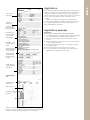
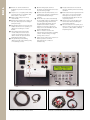
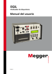
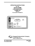
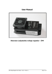
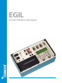
EGIL
Circuit Breaker Analyzer
EGI L
EGIL
Circuit breaker analyzer
EGIL™, which incorporates benefits gained from experience with our larger instrument, is intended for circuit
breakers with one contact per phase. Smaller and simpler, EGIL is equally versatile – and EGIL's price makes it
attractive to small power plants. Moreover, it provides an ideal supplementary instrument for maintenance
departments at large power companies.
EGIL is designed to test circuit breakers having one main contact per phase. Its three time channels are connected
together on one side. Events at parallel contacts equipped with pre-insertion resistors are recorded and displayed
simultaneously. There are two separate time channels for measurement of auxiliary contacts. To simplify on-site
hookup, EGIL comes with ready-made multi-cable sets for both main and auxiliary contacts.
Coil currents are measured automatically and presented together with other readings immediately after testing on
the display window or via the built-in printer. EGIL is easy to use – a built-in sequencer (program unit) sets the
instrument automatically for the next sequential breaker operation.
Intended primarily for measuring travel (motion), the optional analog input channel finds many other uses as well. If
this channel is not installed, all associated menu commands are hidden.
EGIL can also be equipped with an optional serial interface (RS-232C) for communication with a personal computer
(PC) and the CABA Win* Circuit Breaker Analysis Software.
Space for your
report data
Space for your
comments
Parameters you
have selected for
breaker operation
Parameters you
have selected for
travel (motion)
measurement
Filtering you have
selected for time
results
Tabular printout of
time measurements
at main contacts
Tabular printout
of time measurements at auxiliary
contacts
Tabular printout
of travel (motion)
calculations
Graphical printout
Auxiliary contact,
close circuit
Main contacts
Auxiliary contact,
trip circuit
Example of report printed out on the built-in printer. Close-Open operation. Time, coil currents and travel (motion) were measured. (Travel measurement is optional.) The above example is 55% of actual size.
EGIL is intended primarily for testing high-voltage circuit breakers at
medium-level voltages. There must not, however, be more than one
breakpoint per phase since the time channels are not galvanically
isolated. Contact times are recorded for main contacts, pre-insertion
resistor contacts and auxiliary contacts. Coil currents are also
recorded.
Besides the actual measurement values several parameters
according to IEC standards are calculated and shown in the report,
e.g. closing and opening time, difference between phases, overtravel, CO and OC time (and others).
Application example
IMPORTANT
Read the User’s manual before using the instrument.
1. Ground EGIL using the included ground cable. Make certain that
the circuit breaker is closed and grounded on both sides.
2. Connect the main contact cable set to EGIL and the circuit
breaker.
3. Connect the auxiliary contact cable set to the a- and b-contacts
on the operating mechanism.
4. Connect the EGIL sequencer to the close- and trip-coils and to
the auxiliary voltage.
5. Remove the breaker’s ground connection on one side.
6. You are now ready to proceed with the test. Simply turn the
MEASURE rotary switch and read the results.
EGI L
Application
EGI L
❶ Built-in coil current measurement.
Readings are presented on autoscaled
graphs.
❷ Sequencer for coil signals permits delays
to be introduced for coil impulses that
differ relative to each other.
❸ Mains voltage changeover switch,
115/230 V AC.
❹ Built-in printer features autoscaling, 114
mm (4,5”) wide paper can be changed
quickly and easily.
❺ Galvanically isolated sockets ensure safe,
reliable disconnection of operating coil
cables before working in or on the
breaker.
❻ Three timing channels. Both main
contacts and pre-insertion resistor
contacts can be timed on the same
channel. Results are presented both
graphically and numerically.
❼ Two galvanically isolated timing
channels. Can be used for timing of dry
or wet auxiliary contacts.
❽ Optional analog input channel is
intended for measuring travel (motion) or
any other analog voltage.
❾ Optional serial (RS-232C) interface for a
computer (PC). Supports communication
with the CABA breaker analysis
software.
❿ Menu-driven procedures automatically
invoke default settings to eliminate timeconsuming presetting. All menu lines
associated with uninstalled optional
equipment are hidden to enhance
simplicity. For the basic egil unit you
simply connect the multicable sets and
turn the MEASURE knob.
⓫ AUX 1 & 2 buttons used for time
channels that measure timing of auxiliary
contacts. Contactsensing or voltagesensing can be selected.
⓬ Switch used to start a preset sequence of
breaker operations for which
measurements are conducted
simultaneously.
❶
❷
❻
❸
⓭ Designed and tested to meet the CE
emission, immunity and electrical safety
standards.
⓮ Breakerstate indicator. Egil measures the
state (open or closed) of the breaker,
whereupon the sequencer sets the
instrument automatically for the next
sequential operation.
⓯ Switch used to set the breaker to the
desired state without activating the
measurement channels.
⓰ Fast-select buttons for frequently used
functions such as selecting a sequence of
operations (C, O, C-O, O-C or O-C-O)
and printing results.
❼
❽
❾
❺
❿
❹
⓮
⓫
⓯
⓰
⓬
⓭
Transducer cables GA-00041 and GA-00042
Multicable sets GA-00160 and GA-00170 and cable set GA-00082
Specifications are valid at nominal input voltage and an ambient
temperature of +25°C, (77°F). Specifications are subject to change
without notice.
Environment
Application field
The instrument is intended for use
in medium-voltage substations and
industrial environments up to 130 kV.
Temperature
Operating
0°C to +50°C (32°F to +122°F)
Storage & transport -40°C to +70°C (-40°F to +158°F)
Humidity
5% – 95% RH, non-condensing
CE-marking
LVD
EMC
Low Voltage Directive 73/23/ EEC am.
by 93/68/EEC
EMC Directive 89/336/EEC am. by
91/263/EEC, 92/31/EEC and 93/68/EEC
General
Mains voltage
Power consumption
Dimensions
Instrument
Transport case
Weight
Display
Available languages
115 / 230 V AC (switchable), 50 / 60 Hz
100 VA (max)
360 x 210 x 190 mm
(14.2” x 8.3” x 7.5”)
420 x 300 x 230 mm
(16.5” x 11.8” x 9.0”)
6.3 kg (14 lbs). 10 kg (22 lbs) with accessories and transport case
LCD
English, German, French, Spanish,
Swedish
Measurement section
Time measurement
Measurement time
Resolution
Number of channels
Time base inaccuracy
Status thresholds
Closed
Resistor
Open
Open circuit voltage
Short circuit current
1 to 100 s
0.1 to 10 ms
3 with common ground
0.05% of the reading ± resolution
Breaker operation
Sequences
Continuous current
Max current
Contact function
Contact characteristics
Make/Break capacity
Start breaker operation
Pulse length
Pulse delay
Working voltage
C, O, C-O, O-C, O-C-O
5A
25 A during 300 ms, rest time 1 min
Two independent control functions
Non bouncing, closing time max. 0.1
ms
25 A, 250 V (AC or DC) per contact
function
By rotary switch
Adjustable in steps of 10 ms
Adjustable in steps of 10 ms
250 V AC / DC
Motion (optional)
Number of channels
Max cable length
1 independent
10 m (33 ft)
Input
Range
Resolution
Inaccuracy
Transducer resistance
Input impedance
-4 V to +4 V
2 mV
1% of the measurement range
1 kΩ to 5 kΩ
150 kΩ
Output
Open circuit voltage
Short circuit current
4,092 V ±4 mV
115 mA
Serial interface for PC (optional)
Type
Format
Speed
Flow control
V24, RS232C
8 bits, 1 stop bit, no parity
1200 - 19200 baud
Xon/Xoff
Printout
Type of printout
Printer
Graphic resolution
Paper width
Graphic and numeric
Thermal printer with fixed print head
8 dots/mm – 203 dpi
114 mm (4.5”)
< 10 Ω ±20%
10 Ω ±20% to 3 kΩ ±20%
> 3 kΩ ±20%
24 V ±20%
100 mA ±20%
AUX 1&2
Number of channels
2, galvanically isolated
Contact-sensing (Dry)
< 600 Ω ±30%
> 600 Ω ±30%
20 V ±20% DC
Short circuit current
25 mA ±20%
Voltage sensing (Wet)
< 8 V (polarity insensitive)
> 13 V (polarity insensitive)
250 V AC / DC
Current measurement
Range
Resolution
Inaccuracy
Working voltage
Art.No.
EGIL
Status thresholds
Closed
Open
Open circuit voltage
Status thresholds
Open indication
Close indication
Working voltage
Ordering information
±25 A per channel, sum of currents is
measured
25 mA
1% of the reading ±100 mA
250 V AC / DC
Basic unit
Complete with:
Time measurement cables, GA-00160, GA-00170
Cable set for sequencer, GA-00082
Transport case, GD-00190
BM-19090
Egil with analog input channel and serial PC
interface
Complete with:
Time measurement cables, GA-00160, GA-00170
Cable set for sequencer, GA-00082
Transducer cable XLR-open, 1 m (3.2 ft), GA-00041
Transducer cable XLR-XLR, 7.5 m (24.6 ft), GA-00042
Serial cable RS-232C
Transport case, GD-00190
BM-19093
Upgrade
From BM-19090 to BM-19093
BM-90060
Optional accessories
See section “Circuit breaker testing accessories”
EGI L
Specifications EGIL
NOTICE OF COPYRIGHT & PROPRIETARY RIGHTS
© 2007, Programma Electric AB. All rights reserved.
The contents of this document are the property of Programma Electric AB.
No part of this work may be reproduced or transmitted in any form or by any
means, except as permitted in written license agreement with Programma
Electric AB.
Programma Electric AB has made every reasonable attempt to ensure the
completeness and accuracy of this document. However, the information
contained in this document is subject to change without notice, and does not
represent a commitment on the part of Programma Electric AB.
TRADEMARK NOTICES
Programma® is a registered trademark of Programma Electric AB.
All other brand and product names mentioned in this document are
trademarks or registered trademarks of their respective companies.
Programma Electric AB is certified according to ISO 9001 and 14001.
Programma Electric AB
Eldarvägen 4
Box 2970
SE-187 29 TÄBY
Sweden
T +46 8 510 195 00
F +46 8 510 195 95
[email protected]
www.programma.se
Subject to change without notice. Art. No. ZI-BM01E R001 Doc. BM0165AE