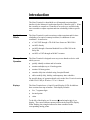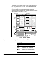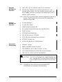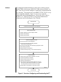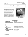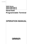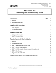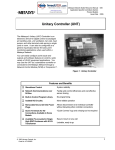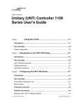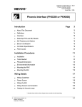
1
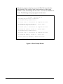
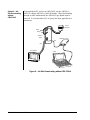
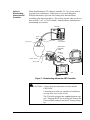
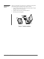
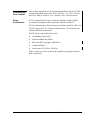
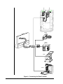
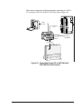
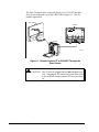
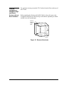
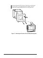
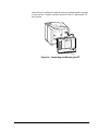
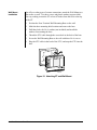
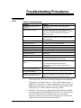
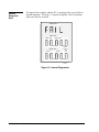
Application Specific Controllers Technical Manual 636.3 Zone Terminal Section Technical Bulletin Issue Date 0395 Zone Terminal lntroduction Page 3 ● Application Details *3 ● Theory of Operation *3 ● Downloading Options *7 Installation Procedures 13 ● Tools Needed 13 ● Physical Dimensions 13 ● Environmental Information 13 ● Installing the Inserts 14 ● Connecting the Zone Terminal *15 ● Physical Installation of Wall Mountings and Bases *19 ● Removing a Mounted ZT *24 Troubleshooting Procedures ● Troubleshooting Chart ● Internal Diagnostic Error Ordering Information 25 *25 26 *27 * Indicates those sections where changes have occurred since the last printing. © 1995 Johnson Controls, Inc. Code No. LIT-6363014 1 2 Zone Terminal—Zone Terminal Introduction The Zone Terminal is a hand-held or wall-mounted person/machine interface for the Metasys® Application Specific Controller (ASC). It has the versatility to connect to a controller in several ways, and allows the user to monitor or adjust setpoints and time scheduling within a specific zone. Application Details The Zone Terminal is used to monitor or adjust setpoints and for time scheduling of occupied, warmup/cooldown, or shutdown of zone conditions. It connects to: ● a VAV/UNT through a TE-6100 Zone Sensor or CBLCON-0 ● an AHU directly ● ● Theory of Operation an AHU through a Function Module Kit or a CBLCON at the Relay Kit an AHU or UNT through an M100C Actuator The Zone Terminal is designed as an easy-to-use hands-on device with which you can: ● quickly identify an alarm and its location ● monitor and adjust up to 18 analog points ● monitor 18 binary points ● extend a daily time schedule using Occupied Extend ● add or modify daily, holiday, and temporary time schedules For specific theory of operation details, refer to the Zone Terminal section of the HVAC PRO for Windows User’s Manual. Displays The Zone Terminal uses a Liquid Crystal Display (LCD) divided into three sections from top to bottom. Each display includes: ● five, 7-segment digits ● decimal points ● colon To the left of the display are 18 cursors (●) and triangles (▲), 6 per display. The cursors indicate current position in the respective display. When flashing, the triangles indicate an alarm condition in the corresponding analog points. Zone Terminal—Zone Terminal 3 The right side of the ZT display includes 18 pairs of binary indicators--a bar ( | ) for On, and a circle (❍) for Off. These symbols flash when the respective binary point is in alarm. Five LED’s located in the bottom panel include four green Mode Indicators and one red Alarm Indicator. The Alarm Indicator LED flashes when any analog or binary point is in alarm. Display Item List Alarm Triangle Display Cursor Dot ROOFTOP ZTU Display Key 1 OUTDOOR AIR ZONE TEMP STATIC STEPT MIXED AIR LL SP NIGHT HTG STPT NIGHT CLG STPT 2 COOL SET PT HEAT SET PT WARMCOOL ADJ ACT CLG SP ACT HTG SP 3 DISCH TEMP CLG % ON HTG % ON ECON % OPEN MIN POS % OPN Mode Selector Key Mode Selector Panel INSERT 12 On/Off Status ON Display Area 1 1 FAN COOL STG COOL STG HEAT STG HEAT STG OCCUPIED Display Area 21 A/C LIM OPN CHECK FAN CHECK CLG CHECK HTG CHECK ECON DIRTY FILTR Display Area 31 FAN STATUS ECON ENABLE TEMP OCC WARMUP MODE CLG LOCKOUT HTG LOCKOUT Operating Mo de Indicator #1 #2 #1 #2 ALARM MONITOR ADJUST TIME SCHEDULE PASSWORD E N TE R OFF Alarm Light Up/Down Arrow Keys Door MAP1RT4 Figure 1: The Zone Terminal Keys Refer to Figure 1 to locate each of the seven ZT keys. Table 1: ZT Keys Key 4 Zone Terminal—Zone Terminal Description Display Key 1, 2, 3 Moves the cursor through left insert items Operating Mode Selector Moves the LED to the desired operating mode: Monitor, Adjust, Time Schedule, Password (↑) or (↓) Adjust Up or Down changes the numbers in the displays Enter Commits adjustments Required Hardware for Operation AHU, UNT, or VAV controller with 24 VAC transformer ● ZTU100 Zone Terminal comes with a 6-pin coiled cord. Also included are four inserts: one Time Schedule Overlay (remove the paper backing), and three clear inserts with setpoint labels (remove protective plastic backing). ● Note: The UNT/VAV inserts match common configurations right out of the box. The ZT matches the most-used AHU configuration: Mixed Air Single Path. Optional Hardware for Operation Required for Downloading ● TE-6400 Metastat ● TE-6100 Zone Sensor ● FMK102 Function Module Kit ● RLY100/RLY050/RLY002 Relay Kit with CBLCON-0 ● M100C Actuator ● ZTUWMB Wall Mount Base ● ENC100 Enclosure for ZTUUMB ● ZTUUMB Utility Mounting Base with Screws ● ZTUBAG Carrying Case ● EN-WIN101 Window for UPM Enclosure ● CBLPRO-1 or later ● IBM® compatible computer or laptop ● WS-SWHPRO-3 HVAC PRO Release 3 or later ● clear overhead transparency film for the customized inserts ● CBLCON-0 or AHU103/AHU100 and FMK102 ! CAUTION: The ZT must be plugged into a 6-pin telephone-type jack. Plugging the ZT into an 8-pin jack destroys the 8-pin receptacle and prevents the ZT from powering up. Note: CBLPRO-1 or later must be used to download the ZT. CBLPRO-0 is not compatible for downloading. Zone Terminal—Zone Terminal 5 Software ZT configuration and downloading are done with a software program called ZT PRO, which is part of the HVAC PRO software, Release 3 or later. This easy-to-use tool configures, commissions, and downloads the ZT’s data base. The program runs on an IBM PC/XT/AT, PS/2®, or any 100% compatible computer. Figure 2 is an overview of the ZT configuration and downloading process. Refer to the HVAC PRO for Windows User’s Manual (FAN 637.5) for specific information on configuration and downloading the Zone Terminal. Start HVAC PRO Select Zone Terminal from Main HVAC PRO Menu Select Configure ZT Files ● Define display files for single or multiple controllers. ● Define weekly schedules. ● Define holiday schedules. Define ZT Configuration Load File ● Press F2 and select up to three display files. ● Press F2 and select Weekly and Holiday Schedules, which must be executed from ZT. ● Press F2 and select display file corresponding to appropriate controller. ● Select hardware parameters. ● Specify Password Access Numbers. ● Print the Insert and photocopy onto an overhead transparency. ● Attach cable to ZT CBLCON-0 and CBLPRO-1 connection. Select Download ZT ● Set switch at CBLCON-0 to Download. ● Select the desired load file to download. ● Select the communication port. ● When Download Complete message is displayed on the screen, press any key to return to Main ZT PRO Menu. (PC is displayed at ZT during download; resets when download is complete.) ● Unplug cable from ZT CBLCON-0. Reset switch to normal. DWNLDZT2 Exit HVAC PRO Figure 2: Overview--Configuring and Downloading the ZT 6 Zone Terminal—Zone Terminal ! Downloading Options The following section presents four options available for hardware connections necessary to complete the downloading process. Select one. The section includes: ● ● ● ● Using CBLCON-0 CAUTION: Any changes in the configuration of the AHU and UNT/VAV must be updated in the Zone Terminal. Failure to download the ZT after configuration changes to the AHU and UNT/VAV prevents access to the ZT Operating Modes. Using CBLCON-0 or Job Site Downloading with a UNT or VAV (Using CBLCON-0) or Job Site Downloading without CBLCON-0 or Downloading without an ASC Controller Use CBLCON-0 for multiple connections of related equipment. To download, slide the switch on the CBLCON-0 to the download position. The red LED is indication of 24 VAC power. The green LED shows Zone Bus transmissions from the controller. If this LED is off, the Zone Bus wire is open. If this LED is on solid, the Zone Bus is shorted to COMMON. Switch must be in Download position. 24 VAC CO M ZO NE BUS 8 8 6 6 6 CBLCON2 Figure 3: CBLCON-0 Zone Terminal—Zone Terminal 7 Although the program reminds you to put the CBLCON-0 switch in the correct position, if the switch is in the wrong position, or if the wrong CBLPRO is used, downloading does not occur. You must use CBLPRO-1 or later. The following error prompt appears on the screen. ZT PRO - Version 05.10 Building Object File to Download ZT Establishing Communication ZT error (18) -- Invalid or No response from ZT ZT Download Failed, Strike 1 - Trying Again ZT Establishing Communication ZT error (18) -- Invalid or No response from ZT ZT Download Failed, Strike 2 - Trying Again ZT Establishing Communication ZT error (18) -- Invalid or No response from ZT ZT Download Failed, Strike 3 - You’re Out Return Switch on CBLCON to Normal Position Press any key to Continue <Esc>Cancel <F7>View Figure 4: Error Prompt Screen 8 Zone Terminal—Zone Terminal To download a ZT for a VAV/UNT through the TE-6100 Zone Sensor (Figure 5), use a CBLCON-0, CBLPRO-1 or later, and a laptop. UNT or VAV TE-6100 AS - UN T 1 0 1- 0 +15VDC Option 1: Job Site Downloading with UNT/VAV Using CBLCON-0 B IN AR Y IN C OM PWR IN BIN AR Y A N AL O G IN P UTS ZONE BU S 24V AC 24 V AC T O L O A DS B I N A R Y O UT P UT S A N A O UT 8 8 6 B IN A R Y IN CBLPRO-1 or Later CBLCON-0 24 VA C COM C OM 6 6 Laptop DWNLD3 Zone Terminal Figure 5: Job Site Downloading with UNT/VAV Using CBLCON-0 Notes: It is assumed that 24 VAC power has been applied to the controller. The CBLCON-0 switch must be in the Download position. Zone Terminal—Zone Terminal 9 Option 2: Job Site Downloading without CBLCON-0 To download the ZT without an CBLCON-0, use the AHU101-1, AHU103 without AHU102 or AHU100 boards. When downloading through an AHU motherboard, the AHU102 Logic Board must be removed. It is assumed that 24 VAC power has been applied from a transformer. 24 VAC Transformer Brown Orange AHU101-1 Board CBLPRO-1 or Later 8-pin 6-pin Zone Terminal Laptop ahu100-1 Figure 6: Job Site Downloading without CBLCON-0 10 Zone Terminal—Zone Terminal Option 3: Downloading: without an ASC Controller When downloading the ZT without a controller, 24 VAC power must be accessed from a transformer. Where power is accessed through an XFR100 transformer, splice the wire coming from the transformer according to the illustration below. This is only required when you do not have an AHU, VAV, or UNT available. Other hardware connections for downloading are as shown. Transformer G re e n Brown O ra n g e S p lice h e re S p lice h e re M o le x C o n n e cto r 24 VAC R e set B u tto n Switch must be in Download position. HVAC PRO CBLCON-0 CBLPRO-1 or Later Orange - 24 VAC Brown - COM Zone Terminal XFR-ZT Figure 7: Downloading without an ASC Controller ! CAUTION: Connect only one transformer at a time into the CBLCON-0. Connecting more than one controller or transformer at a time may cause a short circuit. The ZT must be plugged into a 6-pin telephone-type jack. Plugging the ZT into an 8-pin jack destroys the 8-pin receptacle and prevents the ZT from powering up. Zone Terminal—Zone Terminal 11 12 Zone Terminal—Zone Terminal Installation Procedures Tools Needed Physical Dimensions ● flat-head screwdriver ● needle-nose pliers ● drill The ZT unit measures 6.88 x 7.31 x 1.52 inch (175 x 186 x 39 mm), and weighs 1.25 lb (0.57 kg). A coiled, 6-pin telephone-type cord is included. The cord is 17 inches long and stretches to 5 feet. The ZT contains a 5-year lithium battery. The Wall Mount Base with ZT measures 6.94 x 7.44 x 2.00 (176 x189 x 51 mm). The Utility Mount Base with ZT measures 6.94 x 7.44 x 6.00 (176 x 189 x 152 mm) when mounted on the ENC100. Environmental Information Installation of the Zone Terminal must meet the following standards: ● Ambient operating conditions: 32 to 122°F (0 to 50°C) ● 10 to 90% non-condensing relative humidity ● 86°F (30°C) maximum dew point Notes: Do not mount the Zone Terminal in a vibration area. The atmosphere must be free of corrosive chemical vapors, which may damage electronic equipment. Cleaning of ZT Surfaces ● ● ● Use mild soap and water with a soft cloth to wipe surfaces of the ZT clean. Do not immerse the ZT unit in water. Wipe clean with pure isopropyl alcohol, if surface becomes excessively dirty. Zone Terminal—Zone Terminal 13 Installing the Inserts Before you mount the ZT or connect it to a controller, the clear plastic insert that describes the displayed values must be in place. 1. Lay the ZT flat and press the white tab on the top of the ZT while pulling the front cover towards you. 2. Align the insert to the lower left front of the ZT. 3. Press the pieces back together. INSERT3A Figure 8: Template Installation 14 Zone Terminal—Zone Terminal Connecting the Zone Terminal Prior to final connection, the ZT must be downloaded using the ZT PRO software tool which is part of the HVAC PRO Rev. 3.0 or later. Refer to the HVAC PRO for Windows User’s Manual, Zone Terminal section. Wiring Considerations If ZT is connected 50 feet or less from the controller, install 24 AWG (6-conductor) telephone cable between the controller and the ZT. If ZT is connected up to 500 feet from the controller, install 18 AWG wire. The ZT requires 24 VAC, Common, and Zone Bus. The Zone Bus and Common should be twisted pair. The ZT can be connected directly to the: ● Air Handling Unit (AHU) ● Function Module Kit (FMK) ● Relay Kit (RLY) through a CBLCON-0 ● Actuator (M100C) ● Zone Sensor (TE-6100 or TE-6410) Figure 9 shows you where to locate the telephone-style plugs in each of these components. Zone Terminal—Zone Terminal 15 AHU103 Controller FMK 102 Remote RLY100/50 CBLCON-0 M100C TE-6100 conect2 Figure 9: Connecting the Zone Terminal 16 Zone Terminal—Zone Terminal Other remote connections include permanently connecting to a UNT or VAV using the CBLCON-0 and TE-6100 Zone Sensor (Figure 10). 1 2 3 4 5 6 A NA LOG INP U TS 1 2 3 4 5 6 COM MON A NA L OG INP UT S A NA LOG IN P UTS + 1 5 V DC 1 2 3 24 V A C 4 C O M MO N B INA R Y OU TP U T 1 2 3 4 5 6 B INA R Y OU TP U TS 2 4V A C C O M MO N 6 Switch must be in normal position. 8 8 6 6 0-10V DC Z O NE BUS A NA LOG OUT P UT 24 VAC CO M TO ZON E S TA T 2 4V AC T RA C S C O M MO N B IN A RY INP UT B INA R Y I N Connect VAV/UNT here. 1 2 3 4 5 6 7 8 1 2 3 4 5 6 + 1 5 V DC Connect STAT here. Green LED Red LED Connect ZT here. CO N C T2 Figure 10: Connecting Remote ZT to UNT/VAV with CBLCON-0 and Zone Sensor Zone Terminal—Zone Terminal 17 The Zone Terminal can be connected directly to a VAV/UNT through a Zone Sensor without the use of the CBLCON-0 (Figure 11). This is a portable application. Zone Terminal VAV/UNT O FF +15VDC A S- UNT 101-0 A N A L O G I N P U TS 1 2 3 4 5 6 B INA R Y IN 1 2 3 4 C OM B I N A R Y O U TP U T 1 2 3 4 5 6 0 -1 0 V D C A NA L O G OUT P UT 1 2 PW R IN A N A L O G IN P UTS C O MM O N AN A L O G INP U TS B I N AR Y C O M B I N A R Y IN 24V AC 24V A C T O L O A DS B I N A R Y O U T P U TS A NA L O G OUT P UT C OM M ON ANA O U T TE-6100 CONCT3J Figure 11: Remote Connect ZT to VAV/UNT Through the Zone Sensor ! CAUTION: The ZT must be plugged into a 6-pin telephone-type jack. Plugging the ZT into an 8-pin jack destroys the 8-pin receptacle and prevents the ZT from powering up. 18 Zone Terminal—Zone Terminal Physical Installation of Wall Mountings and Bases For optimum viewing, mount the ZT 65 inches from the floor to the top of the ZT unit. Enclosure Kit and Base Installation Before attaching the Enclosure Kit (ENC100-0) to the wall, remove the rectangular knockouts at either the top or the bottom, depending on which end the wires will run through. Knock wire passage out on top or bottom. KNOCKOUT Figure 12: Remove Knockouts Zone Terminal—Zone Terminal 19 Attach the Enclosure Kit (ENC100-0) to a flat surface or wall for direct connection of the ZT to an application specific controller. Pull wire through before attaching standoffs and screws for the plastic base. MT&BASE Figure 13: Attaching the Enclosure Kit and Utility Mounting Base 20 Zone Terminal—Zone Terminal Attach the base, pulling the telephone jack type cord through the opening as shown below. Plug the cord into the back of the ZT, and snap the ZT into position. CNCT&MT Figure 14: Connecting and Mounting the ZT Zone Terminal—Zone Terminal 21 Wall Mount Installation For office or other types of remote connections, attach the Wall Mount to a flat surface or wall. Use three screws and plastic anchors (not provided). For easy reading, mount the ZT at least 65 inches from the floor to the top of the ZT. 1. Position the Zone Terminal Wall Mounting Base on the wall. 2. Mark the three mounting hole locations and remove the base. 3. Drill three holes for No. 6 anchors (not included) and install the anchors for mounting the base. 4. Thread the ZTU cable through the access hole in the back of the base. 5. Secure the Wall Mounting Base to the wall with three No. 6 screws. 6. Plug the ZTU cable in the back of the ZTU, and snap the ZTU into the base. WALMTZT Figure 15: Attaching ZT and Wall Mount 22 Zone Terminal—Zone Terminal Mounting the ZTU Externally on the UPM Using the wall mounting base, follow the instructions below to mount the Zone Terminal on a UPM. M E TA S Y S N2 AHU103 Zone Bus Zone Terminal Mounted on the Outside A LA R M ztcontr Figure 16: Mounting the Zone Terminal on a UPM 1. Position the Zone Terminal Wall Mounting Base flush on the cover at eye level (approximately 65 inches to top of ZT). 2. Mark mounting holes. 3. Mark cable hole. 4. Drill three size 3/32 inch pilot holes for mounting the base. 5. Drill 5/8 to 1 inch hole for cable. 6. Mount the base to the UPM cover using three No. 6 thread forming or sheet metal screws. Use a No. 6 x 3/4 inch screw for the top hole and two No. 6 x 1/2 inch screws for the bottom screws. Zone Terminal—Zone Terminal 23 Mounting the ZT Behind a Window Enclosure in the UPM The Panel Unit in Poteau, Oklahoma has a bracket available for mounting the ZT behind a window that allows control equipment to be mounted behind the ZT, thereby maximizing the use of the UPM. Contact the Panel Unit for more information. B o ttom V ie w of U P M ZT UNT A LA RM ztin 2 Figure 17: Bracket for Mounting the ZTU Internally in the UPM Removing a Mounted ZT Use a large flat-head screwdriver and insert it in the bottom where the ZT and mounting base come together. Gently pry the ZT out of the mounting base. As you push the screwdriver in, the ZT slides up and then out. REMOVAL Figure 18: Removing Mounted ZT 24 Zone Terminal—Zone Terminal Troubleshooting Procedures Troubleshooting Chart Table 2: Troubleshooting Problem Solution Displays remain blank after ZT is connected No power is getting to the ZT--check for appropriate connections. Displays show only dashes - - - - - ZT unit is operational, but not communicating with the controller. Check the Zone Bus wire/controller. If no wiring errors are found, download the AHU w/HVAC PRO, Release 3 or newer. Displays show all dots . . . Download in ZT does not match connected controller, or download is invalid. Select correct download (ZT load file) and re-load the ZT. Displays show 99999 An entered number is too large to display. Displays show -9999 An entered number is too small to display. Displays show Err 01 Internal RAM/Processor Error* Displays show Err 02 Displays show Err 03 External RAM Error* E2 PROM Error* Displays show Err 04 ROM (Code) Error* Displays show Err 05 Battery Bad** Displays show Err 06 Battery-backed RAM Error* Cannot enter Adjust Mode Has proper Password been entered? Do you have Password access to this mode? Cannot enter Time Scheduling Mode Has proper Password been entered? Do you have Password access to this mode? Is the ZT plugged into the controller selected for Time Scheduling? ZT reverts back to Monitor Mode ZT has timed-out. Re-enter your Password and begin again. One minute lapse in time scheduling has occurred at Midnight Enter 24:00 to cross the day boundary in HVAC PRO. Numbers in the display do not relate to the items listed on the insert The insert is not the correct one for this ZT and Controller. * Verify the insert number by entering Password mode. For Errors 1, 2, 3, 4, and 6--Repower device two or three more times. If error still exists, disconnect ZT and run diagnostics by holding the Display Key 1 and Adjust Down ( ↓ ) Key when the phone jack is plugged in. The word DIAG appears on Display 1 at the start, and all display segments light up for “Pass.” When all segments light, push Display Key 1 two times, and then follow the prompts. ** For Error 5--This is only a warning and indicates the battery-backed data, specifically Time Scheduling, has been lost. If you press Enter, the ZT loads the default time schedule and you may continue. Replace the battery at your earliest convenience. Use a Panasonic® lithium or Ray-O-Vac®--battery number BR2325. Zone Terminal—Zone Terminal 25 Internal Diagnostic Error The figure below explains what the ZT is reporting in the event it fails its internal diagnostic. The digit “1” appears in displays 2 and 3 indicating where the error has occurred. Display Area 1 1 Display Area 2 1 Internal RAM External RAM Display Area 3 ROM Test 2 1 E PROM BatteryBacked Ram Test DIAGFAIL Figure 19: Internal Diagnostics 26 Zone Terminal—Zone Terminal Ordering Information The Zone Terminal includes the ZT, three inserts, one time schedule overlay, and one 6-pin coiled telephone style cord. The Zone Terminal can be ordered from the nearest Johnson Controls branch office or wholesale distributor. Accessories Table 3: Accessories Product Code Series Description AS-ZTUBAG-0 ZT Carrying Case for Portable Applications AS-ZTUUMB-0 Utility Mounting Base w/Screws; Mounts on a Standard ENC100 AS-ZTUWMB-0 Wall mount--Base Only FAN 633.5 Zone Terminal User’s Manual AS-CBLCON-0 Telephone Style Plug Cable Connector for Downloading the ZT EN-WIN101 Window Section Zone Terminal—Zone Terminal 27 Specifications Table 4: Specifications Product Power Requirements Ambient Operating Conditions Zone Terminal AS-ZTU100-1 Power supplied from the AHU/VAV/UNT, 24 VAC at 0.05 A (1.2 VA) 32 to 122°F (0 to 50°C) 10 to 90% Non-condensing Relative Humidity 86°F (30°C) Maximum Dew Point Ambient Storage Conditions -40 to 158°F (-40 to 70°C) 5 to 95% Non-condensing Relative Humidity 86°F (30°C) Maximum Dew Point Dimensions (H x W x D) 6.88 x 7.31 x 1.52 inch (175 x 186 x 39 mm) Shipping Weight 1.25 lb (0.57 kg) Agency Compliance FCC Part 15 Subpart J - Class A Agency Listings UL916 Listed and CSA Certified Plastic Rating UL-5V Flammability: Flame Spread: Oxygen Index UL 94-5V 52-68 (ASTM E 162) 30 (ASTM D 2863) Wire Length 500 ft, No. 18 AWG Twisted Pair 50 ft, No. 24 AWG Phone Cable Termination 6-pin RJ12 Telephone Style Jack Baud Rate Displays Timekeeping Battery Backup Time Scheduling 1200 Baud Asynchronous, Half Duplex Continuous, 5-digit LCD Display of 3 Analog Inputs/Outputs or Setpoints, plus 18 Binary Status/Mode Points 7-day, 24-hour Battery-backed Clock All timekeeping and scheduling stored in RAM under AC power or 5-year lithium battery without AC. Occupied, Warmup, Shutdown for 7 Weekdays, 10 Holidays, 1 Self-canceling Temporary Schedule plus Occupied Extend The performance specifications are nominal and conform to acceptable industry standards. For application at conditions beyond these specifications, consult the local Johnson Controls office. Johnson Controls, Inc. shall not be liable for damages resulting from misapplication or misuse of its products. Controls Group 507 E. Michigan Street P.O. Box 423 Milwaukee, WI 53201 28 Zone Terminal—Zone Terminal FAN 636.3 Application Specific Controllers Technical Manual Printed in U.S.A.