1
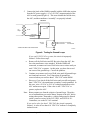
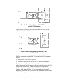
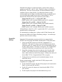
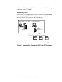
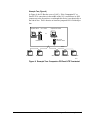
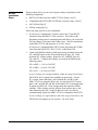
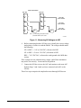
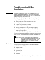
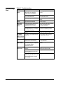
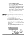
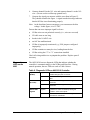
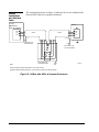
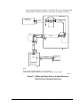
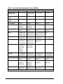
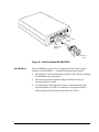
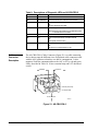
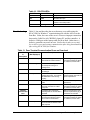
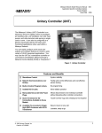
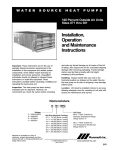
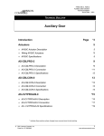
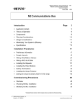
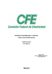
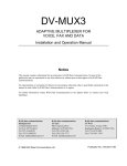
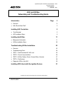
Application Specific Controllers Technical Manual 636.3 Introduction Section Technical Bulletin Issue Date 0995 ASC and N2 Bus Networking and Troubleshooting Guide Introduction Page 3 ● Overview *3 ● Who Should Read This? 3 Installing ASC Controllers 5 ● Tools Required 5 ● ASC Installation Steps 6 Installing the N2 Bus 11 ● Background Information 11 ● N2 Bus Installation Steps 20 Troubleshooting N2 Bus Installation 23 ● Overview 23 ● Troubleshooting Chart 24 ● TEST 1: Earth Grounded 24 VAC Load 25 ● TEST 2: Ground Loop (Isolation) 26 ● TEST 3: N2 Bus Polarity, Shorts, Crossed Wires, Grounds 27 ● TEST 4: Oscilloscope 28 ● Diagnostic LEDs on the AHU 29 Installing UNTs Used with Gas Ignition Devices 31 * Indicates those sections where changes have occurred since the last printing. © 1995 Johnson Controls, Inc. Code No. LIT-6363003 1 Metasys Installation Practices Page 33 ● Quiet Wiring vs. Noisy Wiring 33 ● Using Enclosures for ASCs 33 ● Hard and Soft Grounding 33 ● Using Shielded Cable in Noisy Environments 34 ● Sample Installations with Shielded Cable 36 ● Suppression Devices 39 ● Summary of Installation Practices 41 Zone Bus Communications 43 ● Zone Bus Description 43 ● Cable Pro Description 44 ● Cable Connector Description 46 ● Troubleshooting * Indicates those sections where changes have occurred since the last printing. 2 Introduction—ASC and N2 Bus Networking and Troubleshooting Guide *47 Introduction Overview This document contains important information on how to install and troubleshoot Application Specific Controllers (ASCs) and the N2 Bus on a Companion PC, Panel or LTD system. As our experience with this system matures, we have discovered certain new installation and troubleshooting techniques, which are described in this document. Please use this in addition to the ASC and N2 Bus technical bulletins when installing, commissioning, and troubleshooting ASCs or the N2 Bus. In particular, this document contains the following sections: Who Should Read This? ● Installing ASC Controllers ● Installing the N2 Bus ● Troubleshooting N2 Bus Installation ● Installing UNTs Used with Gas Ignition Devices ● Metasys Installation Practices ● Zone Bus Communications If you are new to installing, commissioning, and troubleshooting Metasys products, it is best to read and use this document in its entirety. However, if you are experienced with Metasys, you probably can just skim this document. Note: To provide the greatest assurance that the ASCs will communicate after initial installation, perform the earth ground test (Figure 4) and the N2 Bus polarity test (Figures 10 and 11). Introduction—ASC and N2 Bus Networking and Troubleshooting Guide 3 4 Introduction—ASC and N2 Bus Networking and Troubleshooting Guide Installing ASC Controllers This section explains how to install ASCs. The VAV and UNT100/101 inputs, outputs, and N2 Bus connections require complete isolation from earth ground. ! WARNING: Do not earth ground the 24 VAC high side of the ASC’s transformer or any of the ASC’s “BO” terminals. If you do, you will damage all of the interface components that are connected, including the Cable Pro, laptop PC, Companion PC, and MM-CVT101. In some cases, earth grounding the common side of the AHUs, LCPs, or UNT110/111s is allowed, because only one earth ground can exist per ASC. Use these procedures to ensure proper isolation. Test the: Tools Required ● field device wiring for proper isolation ● transformer for isolation and correct polarity termination ● connected field devices, transformer, and ASC for proper isolation ● transformer and ASC for proper VA load requirements Obtain the following tools to perform the installation: ● Digital Multimeter (DMM) ● 100K ohm resistor, 1/4-watt ● Double banana plug (optional; shown in Figure 1; available from local electronics store or ITT Pomona Stock No. 34F856 or 34F845) 100K ohm, 1/4-watt Use double banana plug for all tests that require a 100K ohm resistor placed in parallel with DMM. Steps: 1. Connect 100K ohm resistor under plug's prongs. 2. Insert banana plug into DMM. 3. Connect leads of DMM into banana plug. BANANA Figure 1: Double Banana Plug Used with 100K Ohm Resistor Introduction—ASC and N2 Bus Networking and Troubleshooting Guide 5 ASC Installation Steps This section describes how to install ASCs. The ASCs include the Air Handling Unit (AHU) Controller, Lab and Central Plant (LCP) Controller, Unitary (UNT) Controller, and Variable Air Volume (VAV) Controller. Notes: These procedures are not required; however, they are recommended to reduce installation errors. If you are fairly confident that the field wiring has no earth grounds, you may skip Step 2, which instructs you to measure each field wire terminated to the ASC. Skipping this step shortens the procedure. If you skip Step 2 and a field device is earth grounded, it will be caught in Step 5 when the entire ASC is tested. 1. Mount the ASC in an appropriate location as described in its technical bulletin. 2. Before terminating the field wires to the ASC, measure the resistance of each wire to earth ground using an LED test circuit (preferred) or a DMM. For the LED test circuit, assemble the test circuit shown in Figure 2. Then, connect the circuit from each input to earth ground and then to each output to ground. For the DMM test, connect the DMM from each input to earth ground and then to each output to ground (Figure 2). If the LED turns On (or you read a value less than 1 Megohm at any input or output), the circuit is improperly isolated. Replace or repair the wiring or the field device; or, for a binary output, add an isolation relay. Repeat the DMM test. If the LED does not turn On (or you read a value greater than 1 Megohm), the circuit may be properly isolated. (It will not be isolated if there are earth grounds that exist at higher voltages.) A value of infinite ohms indicates a completely isolated circuit at approximately zero volts. Connect this wire to the appropriate ASC terminal and check the next wire. Field Device IN/OUT IN/OUT COM DMM or LED Test Circuit (Preferred Method) (+) (-) 9V Battery Red LED (15/20 mA) 470 ohm 1/4-watt ISOCIRCT Figure 2: Testing for an Isolated Circuit 6 Introduction—ASC and N2 Bus Networking and Troubleshooting Guide 3. Before connecting the transformer to the ASC, connect the input power to the primary leads of the 24 VAC transformer. a. Measure the voltage of each secondary transformer lead to earth ground with the DMM in parallel with a 100K ohm 1/4-watt resistor (Figure 3; if using double banana plug, insert plug into DMM). If you read 5 VDC/VAC or greater, the transformer is earth grounded. If this is a VAV or UNT100/101, you’ll need an isolation transformer in order to isolate the connections from earth ground and protect system components. Wire a separate 24 VAC to 24 VAC isolation transformer (such as the Y65) to the ASC. If this is any other ASC, make sure the ground is on the common side of the transformer, not on the 24 VAC side. If you read less than 5 VDC/VAC, the circuit is properly isolated. Usually a value less than 0.10 VDC/VAC indicates a completely isolated circuit. Line Voltage 24 VAC 100K ohm 1/4-watt DMM 100K ohm 1/4-watt DMM TRANSFM1 Figure 3: Testing the Transformer b. Determine the polarity of the transformer’s leads by using a DMM referenced to earth ground without the 100K ohm resistor. Connect the transformer’s secondary lead with the higher voltage potential to the 24 VAC terminal on the ASC. Connect the transformer’s secondary lead with the lower potential to the 24 VAC Common terminal on the ASC. 4. If the field wires are not yet connected (because you skipped Step 2), disconnect one 24 VAC wire (or turn off AC power) and terminate the field wires. Reconnect power. Introduction—ASC and N2 Bus Networking and Troubleshooting Guide 7 5. Connect the leads of the DMM in parallel with the 100K ohm resistor from the DC power supply (+15 or +30 VDC) output terminal of the ASC to earth ground (Figure 4). This tests whether the field devices, the ASC, and the transformer “assembly” are properly isolated. VAV/UNT100 24 VAC 15 VDC (30 VDC on AHU) Line Voltage 24 VAC 24 VAC COM Field Wiring* 100K ohm 1/4-watt DMM DMM < 5 VDC/VAC = OK (Isolated) DMM > 5 VDC/VAC = Earth Grounded *AICOM, BICOM, ZBUS COM, AOCOM, BOCOM GRDLOOP Figure 4: Testing for Ground Loops If you read 5 VDC/VAC or greater, the circuit is improperly isolated. Follow these steps: a. Remove all the field wires and N2 Bus wires from the ASC, but leave the transformer wires attached. With the DMM still connected, reconnect each set of field wires one at a time until you read 5 VDC/VAC or greater. At this point, you have discovered one cause of the ground loop. Correct the problem. b. Continue to reconnect each set of field wires until all ground loops are found and corrected. You’ll know that all grounds are corrected when you read less than 5 VDC/VAC on the DMM. c. However, if you check all the field wires and you still read greater than 5 VDC/VAC, the transformer secondary is earth grounded. In this case, wire a 24 VAC to 24 VAC isolation transformer to the ASC and measure again. If the value is still 5 VDC/VAC or greater, replace the ASC. Note: Binary outputs are often the culprits of ground loops. Therefore, we recommend that you test the binary outputs of the ASC before testing other points. Remember, a single earth ground is allowed on the common terminal of the LCP, AHU, and UNT110/111 Controllers, not on the 24 VAC terminal. If you read a value less than 5 VDC/VAC, the circuit is properly isolated. A value of less than 0.10 VDC/VAC indicates a completely isolated circuit. 8 Introduction—ASC and N2 Bus Networking and Troubleshooting Guide 6. Connect the DMM across the 24 VAC and the 24 VAC Common terminal of the ASC. Read the voltage with all typical loads energized. A reading of 24-26 VAC is required when the line voltage is nominal. If you read a value less than 22 VAC, make sure the primary voltage matches the transformer’s voltage rating. For details, refer to the appropriate ASC technical bulletin and recalculate the VA requirements for the ASC. You have now completed ASC installation. If this ASC is to operate in standalone mode, you are done with this document. If the ASC is to be connected to the N2 Bus for communication to other devices, go to the next section, Installing the N2 Bus. Introduction—ASC and N2 Bus Networking and Troubleshooting Guide 9 10 Introduction—ASC and N2 Bus Networking and Troubleshooting Guide Installing the N2 Bus Background Information The N2 Bus is a “daisy chain” communications line. Essentially, it consists of three wires which carry three signals: N2+, N2–, and REF. The N2+ and N2– lines carry the actual data signals. The REF line provides a common reference so that each connected device is capable of electrically receiving and transmitting data by creating a common voltage reference among all the devices connected together by the N2 Bus. Three lines are required. It is important that the N2+ and N2– lines are twisted together, which allows most induced noise (common-mode noise) from external sources to affect both lines equally, thereby canceling the noise. In most installations, the N2 Bus works fine with unshielded cable. However, in noisy environments, such as near gas ignition devices and arc welders, shielded twisted wire must be used. Otherwise, the noise disrupts N2 communications and the ASCs. For more details, refer to the section Metasys Installation Practices. An important feature of the N2 Bus is opto-isolation. Isolation prevents interruption of all N2 Bus communication if any of the controllers on the bus become grounded. Table 1 below outlines which controllers have opto-isolation in their N2 Bus circuitry. Table 1: Opto-Isolated Devices N2 Reference Lines Controller or Device Opto-Isolation? AHU Yes LCP Yes MM-CVT101 No UNT100/101 No UNT110/111/120/121 Yes VAV100/101 No The Reference (REF) line helps to provide a common reference from which each device connected to the N2 Bus can discern the voltage levels, and hence, the data, on the N2+ and N2– lines. The N2 Bus may connect devices that are far apart, such as in two different buildings, by allowing line lengths of up to 15,000 feet with two repeaters. If the N2 Bus is wired between buildings, a surge protection module should be used at both ends. Realize that connecting the earth ground of one building to the earth ground in another building can cause current to flow in the line that connects the two grounds together. Because of this, the EIA Standard RS-485 (the N2 Bus) specification states: Introduction—ASC and N2 Bus Networking and Troubleshooting Guide 11 “Where circuit reference is provided by a third conductor, the connection between circuit common and the third conductor must contain some resistance (e.g. 100 ohms) to limit circulating currents when other ground connections are provided for safety.” For the Companion system, the 100 ohm resistor is located in the RS232to-N2 Bus converter (MM-CVT101-0) or in the Companion Panel/LTD. N2 Bus Grounding With N2 Bus grounding in mind, there are a few important facts to know: ● ● Avoiding Unwanted Earth Grounds If earth grounded, the UNT-100/101 units and all VAVs may experience communication problems. This is because the REF line in these units is connected internally to digital common. The UNT-100/101s and all VAV controllers are not designed to be earth grounded, although they often become grounded because field wires connect to earth-grounded field devices, and thus bring ground into the digital common of the device. During installation and commissioning, ensure that no UNT-100/101s or VAVs are earth grounded. (This does not apply to the newer models that isolate the N2 from digital common, including: UNT110/111/120/121, all AHU, and all LCP models.) According to RS-485 specifications, the REF protection on most devices is a 100 ohm resistor. If you miswire the MM-CVT101 or Companion Panel/LTD by connecting any voltage greater than 5 VAC, you may damage the 100 ohm resistor. The resistor is not field serviceable, so if the REF line becomes damaged, you’ll need to send the unit back for repair or replacement. Most N2 devices have isolated N2 communications power supplies, and therefore there is no direct path to earth ground through any of the N2 lines. However, there are three exceptions in which an unwanted earth ground may be introduced into the system: ● ● ● From the MM-CVT101, which is not isolated. It is grounded through pin 7 of the RS-232 connector. Earth ground often comes in from the ground pin on the PC’s power cord or via a printer connected to the computer, which in turn connects to the MM-CVT101. The Companion PC itself is grounded. From a surge protection module (i.e., APT Transient Eliminator) on the N2 Bus. It produces a small amount of leakage to earth ground. From the Cable Pro (CBLPRO-0 or -1 only). If the laptop PC is earth grounded, the Cable Pro would be grounded through the RS-232 ground pin. A single ground will not cause communication problems unless another earth ground path exists in the system to complete a ground loop. 12 Introduction—ASC and N2 Bus Networking and Troubleshooting Guide The ASCs have electrical protection built into the N2 Bus transceiver circuit. It prevents the N2 Bus circuitry from being damaged if someone inadvertently connects a voltage source greater than 5 VDC/VAC between any two or the three N2 Bus terminals. Refer to Table 2. Table 2: Voltage Protection on ASCs N2 Bus Rules Controller Voltage N2 Bus Circuitry Can Withstand AHU < 30 VDC/VAC LCP < 6 VDC/VAC (before 3/1/92) < 12 VDC/VAC (after 3/1/92) MM-CVT101-0 < 30 VDC/VAC UNT < 30 VDC/VAC VAV < 30 VDC/VAC The following table summarizes the rules and maximums allowed for installing the N2 Bus. You may wish to photocopy this table and keep it handy. Table 3: N2 Bus Rules Category Rules/Maximums Allowed General Only one PC/Panel/LTD Version Companion per N2 Bus Maximum Number of Devices 100 devices per PC/Panel/LTD Version Companion Only daisy-chained devices 50 devices per repeater 2 repeaters cascaded Line Length and Type 5000 feet between repeaters 15,000 feet from PC or Panel/LTD to farthest ASC (3 segments of 5000 feet each) 26 AWG twisted pair minimum (stranded 22 AWG or heavier recommended) Terminations 2 switched EOL per segment (preferred) 1 switched EOL per segment (required) N2 EOL Termination The N2 Bus uses End-of-Line (EOL) terminations through the use of jumpers on the Companion Panel/LTD, RS232-to-N2 Bus converter (MM-CVT101), and repeater. N2 Bus circuitry in the ASCs is selfterminating. Figure 5 shows an electrical drawing of the end-of-line wiring for the MM-CVT10-1 and the Panel/LTD Companion. Introduction—ASC and N2 Bus Networking and Troubleshooting Guide 13 5 VDC 1200 ohm N2+ + ASC P R C IN _ W1=MM-CVT101 W2=Companion Panel/LTD + 220 ohm EOL Switch OUT _ N2W2=MM-CVT101 W4=Companion Panel/LTD PRC=Microprocessor 1200 ohm REF EOLWIRE2 Figure 5: End-of-line Wiring for MM-CVT101 and Panel/LTD Companion Figure 6 shows an electrical drawing of the end-of-line wiring for the AHU, VAV, UNT, and LCP controllers. 5 VDC 100K ohm N2+ ASC + IN _ P R C + OU T _ 18-50K ohm N2PRC = Microprocessor 100K ohm REF EOLWIRE1 Figure 6: End-of-line Wiring for AHU, VAV, UNT, and LCP Controllers The EOL terminations on the MM-CVT101 and Panel/LTD Companion place a: ● direct current “bias” on the N2 wires ● 220 ohm resistor from the N2+ to the N2– lines to terminate them The bias prevents the lines from “floating.” If no communications were taking place and all the EOL jumpers were set to the Out position, the N2+ and N2– lines would “float.” That is to say, the bus would have no definite voltage or signal. The receivers would interpret the floating N2 signal as “data,” albeit bad data. To avoid this, and to provide some impedance termination, one or two end-of-line terminations must be made on each N2 Bus segment. 14 Introduction—ASC and N2 Bus Networking and Troubleshooting Guide With the EOL jumpers set to the In position, a positive bias voltage is applied across the N2+ and N2– lines. This bias voltage is referenced to the REF line. The bias resistors and the 220 ohm termination resistors combine to form a voltage divider. By taking the tolerances on the resistors and the power supply variations into account, you should expect to see the following voltage levels on the N2 lines (MM-CVT101 is disconnected from the PC but still connected to the N2 Bus): Voltage from N2+ to N2– = +0.36 to 0.92 VDC* (DMM+ probe on N2+ terminal; DMM- probe on N2– terminal.) Voltage from N2+ to REF = +2.45 to 2.98 VDC (DMM+ probe on N2+ terminal; DMM- probe on REF terminal.) Voltage from N2– to REF = +2.06 to 2.54 VDC (DMM+ probe on N2– terminal; DMM- probe on REF terminal.) *If the difference from N2+ to N2– is greater than 0.36 V, your system should be able to communicate. If communication is taking place, voltage on the N2 Bus fluctuates and therefore the DMM will read these fluctuating voltages. An oscilloscope provides a more accurate reading. Proper EOL Settings Setting the EOL terminations correctly on the devices connected to the N2 Bus is crucial to proper and reliable communication. Follow these rules: 1. Always set the EOL jumpers to In for the Companion PC or Panel/LTD. This device is always set as end-of-line because all the controllers on the N2, namely the ASCs, are self-terminating (they do not have EOL jumpers). Note that, as in Figure 8, the Companion PC or Panel/LTD does not necessarily have to be at the end of line. 2. If possible, terminate the two devices that are at the far ends of the N2 Bus. If one of these devices is self-terminating, terminate the other, which will have an end-of-line jumper. In many cases, this will be the MM-CVT101, Companion Panel/LTD, or repeater. 3. If only one device on the bus can be terminated, jumper it as an end-of-line device. During commissioning, visually check the N2 EOL jumpers at the Companion PC or Panel/LTD. ● ● ● For the Panel/LTD version, the end-of-line jumpers are located on the Panel’s circuit board (W2 and W4). For the PC version, the jumpers are located on the MM-CVT101 (W1 and W2). For the repeater, the jumpers are found under the top cover. Introduction—ASC and N2 Bus Networking and Troubleshooting Guide 15 To illustrate different possible EOL terminations, consider the following examples in Figures 7 through 9. Example One (Figure 7) In this example, the N2 Bus begins at the PC/Panel/LTD Companion and connects several ASCs. This is the simplest network and requires only that the PC/Panel/LTD is set as the end-of-line device. Companion Panel/ LTD Version Companion PC Version or MM-CVT101 Converter = EOL In Panel EOL = In N2 Bus ASC Self Termination ASC ASC Self Termination Self Termination EOLS1 Figure 7: Example One: Companion PC/Panel/LTD Terminated 16 Introduction—ASC and N2 Bus Networking and Troubleshooting Guide Example Two (Figure 8) In Figure 8, the N2 Bus has a row of ASCs. If the Companion PC or Panel/LTD is somewhere in the middle of the N2, it would have its EOL jumpers set to the In position, even though this device is not physically at the end-of-line. This is because at least one jumpered EOL is needed per bus. Companion Panel/ LTD Version Companion PC Version or Panel EOL = In MM-CVT101 Converter = EOL In N2 Bus ASC ASC Self Termination Self Termination ASC Self Termination ASC Self Termination ASC Self Termination EOLS2 Figure 8: Example Two: Companion PC/Panel/LTD Terminated Introduction—ASC and N2 Bus Networking and Troubleshooting Guide 17 Example Three (Figure 9) In the third example (Figure 9), a repeater is placed near the middle of the N2 Bus. Side A of the repeater has its EOL set to Out, but side B has its EOL set to In, since its segment needs a jumpered EOL. Also, the Companion PC or Panel/LTD has its EOL jumpers set to In. Companion Panel/ LTD Version Companion PC Version Repeater A B A:EOL=Out or MM-CVT101 Converter = EOL In B:EOL=In ASC Panel EOL = In Self Termination N2 Bus ASC ASC ASC ASC ASC Self Termination Self Termination Self Termination Self Termination Self Termination EOLS3 Figure 9: Example Three: Repeater Used on N2 Bus 18 Introduction—ASC and N2 Bus Networking and Troubleshooting Guide Important N2 Bus Characteristics Table 4 lists characteristics of various Companion devices that are important to installing and commissioning these devices. Note that some devices do not have EOL jumpers, but have the bias voltage permanently applied to the N2+ and N2– lines. Other devices may or may not have isolation of the REF line to the device’s ground. Isolation problems with communication could possibly result, depending on the situation in which the N2 lines are used. Refer to the Troubleshooting N2 Bus Installation section of this document for more details. Table 4: N2 Bus Characteristics for Various Companion Devices Device Type Isolated N2? N2 REF Connection N2± Protection Bias Value EOL Type AHU Y Transformer isolated from digital common and earth ground Transient voltage 100K ohm suppressors and PTC1 on unit Self Termination CPN201 Y 100 ohm resistor to isolated transformer common Transient voltage suppressors and PTC on unit 1.2K ohm Jumper LCP2 Y Transient voltage suppressors 2 100K ohm Self Termination2 MM-CVT1013 N3 Transformer isolated from digital common and earth ground 100 ohm resistor to common3 Transient voltage suppressors and PTC on unit 1.2K ohm Jumper N2 Repeater Y Transformer isolated from digital common and earth ground Transient voltage suppressors 1.2K ohm Jumper UNT100/1014 N4 Tied to digital common Transient voltage suppressors and PTC on unit 100K ohm Self Termination UNT110/111/ 120/1215 Y5 Transformer isolated from digital common and earth ground Transient voltage suppressors and PTC on unit 100K ohm Self Termination VAV100/1014 N4 Tied to digital common Transient voltage suppressors and PTC on unit 100K ohm Self Termination Notes: 1 PTC=positive temperature coefficient thermistor; i.e., a temperature sensitive resistor that acts like a resettable fuse. 2 LCPs manufactured before 1/91 should not be used at the end-of-line. LCPs manufactured after 2/92 have transient voltage suppressors for N2+ and N2– protection. 3 MM-CVT101 REF terminal connects to communications ground and earth ground through the PC. 4 The UNT100/101 and VAV100/101 have N2 REF connected to digital common. Digital common or 24 VAC must never be connected to earth ground. 5 The UNT110/111/120/121 have isolated N2 REF. Introduction—ASC and N2 Bus Networking and Troubleshooting Guide 19 N2 Bus Installation Steps This procedure allows you to test for proper voltage and polarity of the following components: ● RS232-to-N2 Bus converter (MM-CVT101) [Steps 1 and 2] ● Companion Panel/LTD’s RS-485 N2 Bus converter [Steps 1 and 2] ● ASC N2 Bus [Step 3] ● N2 Bus wiring [Step 4] Follow the steps specific to your installation. 1. If you have a Companion PC Version, remove the 25-pin RS-232 connection from the MM-CVT101 converter. This removes the fluctuating voltage due to communications and allows you to read the DC bias voltage. Disconnect the N2 Bus wires. Wire the transformer to the MM-CVT101 and plug into a 120 VAC source. If you have a Companion Panel/LTD Version, disconnect the N2 Bus wires from the Panel/LTD. Wire 24 VAC to the Panel/LTD. 2. Connect the DMM (without a 100K ohm resistor installed) across the N2+ and REF inputs on the N2 terminal block (Figure 10). Write down the DC voltage reading. Repeat for N2– and REF, then for N2+ and N2–. Compare the voltages you read on the DMM to the following values: N2+ to REF = +2.45 to 2.98 VDC N2– to REF = +2.06 to 2.54 VDC N2+ to N2– = +0.36 to 0.92 VDC If your readings are not approximately within the ranges listed above, the N2 EOL device jumpers are probably set incorrectly. For the PC Version, ensure that pins 1 and 2 on both W1 and W2 of the MM-CVT101 are jumpered (EOL=In). For the Panel/LTD Version, pins 1 and 2 on both W2 and W4 of the Panel/LTD circuit board must be jumpered (EOL=In). If not, jumper them and repeat the DMM readings. If the voltages read are still not close to those above, and, after connecting the ASCs to the N2 Bus, the ASCs are still not communicating, replace the MM-CVT101 or Companion Panel/LTD. If your readings are approximately within the ranges listed above, the N2 EOL device jumpers are set correctly. Go on to Step 3. 20 Introduction—ASC and N2 Bus Networking and Troubleshooting Guide N2 Bus Terminal Block on MM-CVT101 or Panel/ LTD Companion N2 + N2+ to REF +2.45 to 2.98 VDC N2 - N2- to REF +2.06 to 2.54 VDC REF GND N2+ to N2+0.36 to 0.92 VDC DMM Note: For best reading, place probe on metal plate inside terminal, not on screw. VOLTAGE Figure 10: Measuring RS-485 N2 Bus Converter Circuitry 3. Power the ASC. For LCPs manufactured before January 1991, go on to Step 4. For LCPs manufactured after January 1991, and all other ASCs, continue with this step. Before connecting the N2 Bus, check the voltage and polarity of the N2 DC bias voltages on the ASCs. Do so by connecting the DMM across N2+ and REF (Figure 11). Write down the reading. Repeat for N2– and REF, then for N2+ and N2–. Compare the voltages you read to the following values: N2+ to REF = +2.45 to 2.98 VDC N2– to REF = +2.06 to 2.54 VDC N2+ to N2– = +0.36 to 0.92 VDC If your readings are not (approximately) at these values and the ASC does not communicate, replace the ASC. If your readings are within these values, go on to Step 4. Introduction—ASC and N2 Bus Networking and Troubleshooting Guide 21 N2 Bus Terminal Block UNT / VAV AHU / LCP N2 - N2 + N2 + N2 - N2+ to REF +2.45 to 2.98 VDC N2- to REF +2.06 to 2.54 VDC REF ZBus REF DMM DMM N2+ to N2+0.36 to 0.92 VDC Note: For best reading, place probe on metal plate inside terminal, not on screw. VOLTAGE2 Figure 11: Measuring N2 Voltages at ASC 4. Before connecting the three N2 Bus wires, identify the correct voltage and polarity of each wire with the DMM. The voltages should match the following: N2+ to REF = +2.45 to 2.98 VDC, referenced to REF N2– to REF = +2.06 to 2.54 VDC, referenced to REF REF = ≤1.0 VDC/VAC, referenced to earth ground with 100K ohm resistor If the voltages are not within the above ranges, end-of-line termination may not be set correctly. Locate and fix the problem. 5. Connect the N2 Bus wires to the ASC and continue to the next ASC. Perform Steps 3 and 4 until you have connected each ASC to the N2 Bus. These five steps comprise the simplest but most thorough N2 Bus test. 22 Introduction—ASC and N2 Bus Networking and Troubleshooting Guide Troubleshooting N2 Bus Installation Overview You need to troubleshoot the N2 Bus if the Companion system is not properly communicating with the ASCs. This section first presents a troubleshooting table. The table covers many ASC or N2 communication problems and suggests which actions to take. Second, specific troubleshooting tests are given. Before trying one of these tests, you may be able to determine the cause of the problem by asking yourself the following questions: ● Are the N2 Bus wires securely terminated to each ASC? ● Is the N2 polarity correct? ● Is the ASC powered and ready to respond? ● Are the end-of-line device settings correct? ● Have you cycled power on an ASC after changing its address? Is the W3 loopback jumper on the Companion Panel/LTD fully pushed down on pins 1 and 2? ● Are the ASCs configured properly with the correct number of points? ● The tests are designed to find opens, shorts, ground loops, or crossed wires on the N2. Third, this section describes the diagnostic LEDs on the AHU. ! Tools Required CAUTION: To avoid electrical shocks when troubleshooting, always measure the REF to earth ground voltage with a 100K ohm resistor installed at the DMM. If linevoltage is measured, have a qualified electrician locate the fault. The tests covered in this section require the use of these components: ● Digital Multimeter (DMM) ● 100K ohm resistor ● 9-volt battery ● red LED test light ● 470 ohm resistor ● oscilloscope Introduction—ASC and N2 Bus Networking and Troubleshooting Guide 23 Troubleshooting Chart Table 5: Troubleshooting Symptom Possible Cause N2 Bus is offline. EOL jumpers and/or W3 jumper on Install EOL jumpers and W3 jumper MM-CVT101 or Companion properly. Panel/LTD are not installed. Action MM-CVT101 is not plugged into PC or 120 VAC source. Plug MM-CVT101 into PC or plug it into a 120 VAC source. N2 Bus polarity is incorrect. Re-wire N2 Bus wires for proper polarity. AHU continually resets. An AI point greater than 10 VDC is Disconnect the AI or insert the connected to the AHU102. “current” jumper. ASC cycles online and offline. A read-only point is defined in the Companion data base as a read/write point (AO or BO). Delete the AO or BO point and read it as an AI or BI point to the Companion data base. A Companion process is using an unconfigured point (i.e., not listed in HVACPRO.SYM file). Delete the use of the unconfigured point in the Companion process. Two or more ASCs have the same Change each duplicate ASC address. address to a unique number. AO and BO points on the UNT-111 are not communicating. The UNT111 was downloaded as a UNT110. Re-download the UNT, this time specifying it as a UNT111. UNT is offline. Points BO-9 and BO-10 are defined in the UNT data base. Delete the use of BO-9 and BO-10 from the data base. UNT100/101 or VAV is offline. The UNT100/101 or VAV is grounded through the Companion PC or through another UNT100/101 or VAV. Disconnect the ground between the devices. ASC does not come online. Two or more ASCs have the same Change each duplicate ASC address. address to a unique number. The address of the ASC was changed without its power being cycled afterward. Cycle power on the ASC. The ten minute delay after downloading the ASC has not yet expired (HVAC PRO Release 1.0 or earlier). Wait until the delay expires or cycle power. 24 Introduction—ASC and N2 Bus Networking and Troubleshooting Guide This test applies only to the VAV100/101 and UNT100/101 Controllers only. You’ll need a 100K ohm resistor and a DMM to perform this test. Follow these steps: TEST 1: Earth Grounded 24 VAC Load 1. If you have a Companion PC Version, remove the 25-pin RS-232 connection from the MM-CVT101 converter. This removes the fluctuating voltage due to communications and allows you to read the DC bias voltage. Plug the converter into a 120 VAC source. If you have a Companion Panel/LTD, connect the Panel to a 24 VAC source. 2. Connect a 100K ohm 1/4-watt resistor across the DMM. (For easier installation, insert a double banana plug into DMM.) 3. If you cannot guess which ASC may be causing the ground loop, follow Steps 3a and 3b below. If you suspect which ASC is causing the ground loop, follow Step 3c on the next page. a. Connect one DMM lead to REF, N2+, or N2– and the other to earth ground (Figure 12). Read the VDC/VAC scale on the DMM. If the value is greater than 1 VDC/VAC, a ground loop is present and therefore the N2 Bus is not properly isolated. Subdivide the N2 Bus and measure again. Continue to subdivide the bus until you locate the source of the problem. Correct the isolation problem and measure again. If the value is less than 1 VDC/VAC, the N2 Bus is properly isolated. A value less than 0.10 VDC/VAC indicates a completely isolated circuit. Companion Panel/ LTD or MM-CVT101* UNT100/101 or any VAV N2+ N2+ N2- N2- REF REF If DMM < 1 VDC/VAC = OK (Isolated) If DMM > 1 VDC/VAC = Ground Loop * RS-232 cable disconnected. Note: F or best reading, place probe on m etal plate inside term inal, not on screw . DMM KOHMRST 100K ohm 1/4-watt Figure 12: Measuring N2 Bus Wires to Earth Ground Introduction—ASC and N2 Bus Networking and Troubleshooting Guide 25 b. Repeat Step 3a for the other two N2 Bus wires. c. At the ASC that you suspect is causing the ground loop, measure its +15 VDC (or +30 VDC) terminal to earth ground using the DMM in parallel with a 100K ohm resistor. If the value is greater than 5 VDC/VAC, disconnect the N2 Bus at the ASC. Measure the VDC terminal again. If the value is still greater than 5 VDC/VAC, a ground loop is present at that ASC. Locate and correct the isolation problem and measure again. If the value is less than 5 VDC/VAC, the ground is corrected. Reconnect the N2 Bus and measure again. If the value is greater than 5 VDC/VAC, ground sources are present at other ASCs or the N2 Bus. If the value is less than 5 VDC/VAC, the N2 Bus and ASC are properly isolated. TEST 2: Ground Loop (Isolation) For this test, you’ll need a red LED test light, a 470 ohm resistor, and a 9 volt battery. Follow these steps, referring to Figure 13: 1. Disconnect the N2 Bus wires from the Companion PC or Panel/LTD. 2. Assemble the test circuit as shown in Figure 13 or purchase one with a power supply of 9 volts or greater. 3. Connect the ground lead of the battery to earth ground. 4. Connect the positive lead from the test light to one of the N2 Bus wires. If the LED lights when you connect the N2 Bus wire, that particular wire is grounded or improperly isolated. Subdivide the N2 Bus in half and repeat Steps 3 and 4. Continue to subdivide the bus until you find the location of the problem. Correct the grounded condition and measure again. If the LED does not light when you connect the N2 Bus wire, the bus is properly isolated from earth ground. 5. Repeat Step 4 for the other two N2 Bus wires. N2+ N2REF Test Circuit (-) (+) 9V Battery Red LED (15/20 mA) 470 ohm 1/4-watt LEDTEST Figure 13: Ground Loop Test 26 Introduction—ASC and N2 Bus Networking and Troubleshooting Guide TEST 3: N2 Bus Polarity, Shorts, Crossed Wires, Grounds You’ll need a DMM to perform this test. By connecting the DMM to each N2 Bus wire, you’ll be able to detect polarity, shorts, crossed wires, and grounds. Follow these steps, referring to Figure 14: 1. If you have a Companion PC Version, remove the 25-pin RS-232 connection from the MM-CVT101 converter. This removes the fluctuating voltage due to communications and allows you to read the DC bias voltage. Plug in the converter’s transformer into a 120 VAC source. If you have a Companion Panel/LTD Version, make sure the Panel/LTD is powered with 24 VAC. Note that the voltage reading on the DMM may fluctuate, since the bus will be communicating. 2. Connect the DMM across the N2+ and REF screws on the N2 terminal block (Figure 14). Write down the DC voltage reading. Repeat for N2– and REF, then for N2+ and N2–. Compare the voltages you read on the DMM to the following values: N2+ to REF = +2.45 to 2.98 VDC N2– to REF = +2.06 to 2.54 VDC N2+ to N2– = +0.36 to 0.92 VDC If your readings are not approximately within the ranges listed above, that particular wire is grounded, shorted, or crossed with another wire. Correct and measure again. If your readings are approximately within the ranges listed above, the bus is properly wired. N2 Bus Terminal Block on MM-CVT101 or Panel/ LTD Companion N2 Bus Terminal Block AHU / LCP UNT / VAV N2 + N2 REF GND N2 - N2 + N2 + N2 - REF REF DMM ZBus DMM DMM N2+ to REF N2- to REF N2+ to N2+2.45 to 2.98 VDC +2.06 to 2.54 VDC +0.36 to 0.92 VDC Note: For best reading, place probe on metal plate inside terminal, not on screw. POLARTY Figure 14: Test for N2 Bus Shorts, Crossed Wires, Grounds Introduction—ASC and N2 Bus Networking and Troubleshooting Guide 27 3. Check the voltage and polarity of the N2 DC bias voltages at the ASC. Do so by connecting the DMM across N2+ and REF (Figure 14). Write down the reading. Repeat for N2– and REF, then for N2+ and N2–. Compare the voltages you read to the following values: N2+ to REF = +2.45 to 2.98 VDC N2– to REF = +2.06 to 2.54 VDC N2+ to N2– = +0.36 to 0.92 VDC If your readings are not (approximately) at these values, that particular wire is grounded, shorted, or crossed with another wire. Correct and measure again. If your readings are within these values, the bus is properly wired. TEST 4: Oscilloscope You can use an oscilloscope to pinpoint communication faults over the N2 Bus. The procedure requires a 2-channel scope with an A minus B function or an A plus B with B inverted function. Follow these steps: 1. Plug the scope into a grounded electrical outlet. 2. Set both channels to 2 volts per division. Both channels must have the same gain or volts per division setting. 3. With no signal applied, adjust each channel’s vertical position at the same graticule on the screen (i.e., center screen). 4. Select the channel A minus B function. If your scope does not have this function, select the Add function (channel A ADDED to B then INVERT channel B). 5. Select the 0.5 mS horizontal range. 3 to 10 V pp (including +0.5 VDC bias) 0 V- Ch 1 = 2 V/div. T/div .5 mS SCOPESG Figure 15: N2 Bus Signal as Measured with Oscilloscope 28 Introduction—ASC and N2 Bus Networking and Troubleshooting Guide 6. Connect channel B to the N2– wire and connect channel A to the N2+ wire. (Do not use the oscilloscope ground lead.) 7. Compare the signal you measure with the waveform in Figure 15. They should resemble the figure. A signal outside this range indicates that the N2 Bus is not functioning properly. Note: At the dead time between messages, you can measure the bias voltage. In this figure, it is 0.5 VDC. Factors that can cause improper signal levels are: ● N2 Bus wires are not polarized correctly (i.e., wires are reversed) ● N2 cable runs are too long ● breaks in the 24 AWG wire ● an ASC has malfunctioned ● N2 Bus is improperly terminated (e.g., EOL jumpers configured improperly) ● N2 Bus contains too many devices, loading down the bus ● N2 Bus wiring has “T” or “Y” connections installed Check all wiring and devices to pinpoint the problem. Replace parts if necessary. Diagnostic LEDs on the AHU The AHU102-0 has two diagnostic LEDs that indicate whether the controller is communicating over the N2 Bus and Zone Bus. During normal operation, the two LEDs are used as Table 6 shows: Table 6: Diagnostic LEDs on AHU102-0 Controller Top LED (N2 Bus) Bottom LED (Zone Bus) Top and Bottom LEDs Together Single blink The AHU is receiving but has not transmitted over the N2 Bus during the past 1.5 seconds. Double blink The AHU is receiving and transmitting data over the N2 Bus. Single blink The AHU is transmitting but not receiving over the Zone Bus. Double blink The AHU is transmitting and receiving data over the Zone Bus. Double blink together The AHU102-0 is resetting. An AI point with a value greater than 10 VDC is most likely causing this problem. Check current inputs. Both off Power to the AHU is not on. Check the green LED on the AHU101 motherboard. Introduction—ASC and N2 Bus Networking and Troubleshooting Guide 29 30 Introduction—ASC and N2 Bus Networking and Troubleshooting Guide Installing UNTs Used with Gas Ignition Devices Gas ignition devices for rooftop units require that you use shielded wiring to a UNT Controller. These devices generate very high levels of electrical noise that can interfere with N2 communication. For information about how to install these devices in rooftop units, refer to the UNT Controller Technical Bulletin in this manual. Introduction—ASC and N2 Bus Networking and Troubleshooting Guide 31 32 Introduction—ASC and N2 Bus Networking and Troubleshooting Guide Metasys Installation Practices Quiet Wiring vs. Noisy Wiring This document uses the terms “quiet” wiring and “noisy” wiring. With wiring gas ignition devices especially, it is important to know the difference between the two. Quiet Wiring--Wiring that is free of transients. This wiring includes binary inputs, analog inputs and outputs, 24 VAC power, and communication buses. Noisy Wiring--Wiring that is subjected to transients because of its proximity to sources of electrical noise, or because of the loads to which the wiring is connected (e.g., switched low-voltage loads, switched linevoltage loads, gas ignition, and line-voltage distribution). Routing quiet wiring near noisy wiring requires that the quiet wiring is shielded. Low voltage is defined as 24 VAC. Line voltage is 120 VAC or higher. Using Enclosures for ASCs We recommend that all ASCs are installed in enclosures, especially in noisy areas. The ENC100 or BZ1000-7 works well. We also recommend that the enclosures are earth grounded. Placing ASCs inside another piece of equipment which contains a metal housing (e.g., a rooftop unit or a motor control center) does not constitute locating the control device inside a quiet metal enclosure. While the location may provide physical protection for the control device, the presence of electrical noise makes it a noisy box. Therefore, always use a separate grounded metal enclosure for noisy environments. Hard and Soft Grounding Wiring the ASCs and other devices involves some type of grounding. It is important to know the difference between the two types: hard ground and soft ground. Hard Ground--an electrical connection to earth through a conductor, such as steel or other metal. A hard ground is usually necessary for safety reasons. Hard ground is also referred to as earth ground, chassis ground, building steel, building counterpoise, and green-wire ground. Soft Ground--an electrical connection to earth ground through a capacitor, such as a 560 pF capacitor. A soft ground provides high frequency signals, such as 10 MHz, a low impedance path to earth. Power line frequencies, such as 50/60 Hz, provide a high impedance to the earth. Introduction—ASC and N2 Bus Networking and Troubleshooting Guide 33 In most equipment locations, whether or not to provide a low impedance connection to earth ground depends on the circumstances. The high frequency components of electrical noise can render a long wire connection to ground practically useless because of the wire’s inductance. Wherever possible, connecting a shield to a large sheet metal enclosure, such as a rooftop unit, is much better than trying to find a “true” earth ground. If a metal enclosure is not available, tie the shield to one of the following ground connections (listed in order of preference): 1. Direct bond to building counterpoise ground system. 2. Direct bond to main building structural steel (e.g., bolt into threaded hole). 3. Bond to ground rod installed a minimum of two feet below minimum water table depth. 4. Bond to conduit or electrical distribution box. 5. Bond to nearby metal water pipe (preferably copper). Note: In all cases, make the bond to ground as short as possible. Derate a ground point by one level (in order of preference) for each 50 feet of conductor run between the ground point and the equipment to be grounded. For example, a water pipe bond located 10 feet away is preferable to a structural steel bond located 150 feet away. The recommended gauge for the ground wire is 10 or 12 AWG. Using Shielded Cable in Noisy Environments Metasys was specifically designed to use unshielded cable. In most situations, the N2 Bus functions reliably with this type of cable. However, some devices emit very high levels of electrical noise. Examples include radar, magnetic resonance imaging equipment, arc welders, and gas ignition systems. Use shielded cable for these devices. A gas ignition system requires that you use shielded cable on the sections of the N2 Bus that are close to the spark. This section outlines the standard practices you must follow when using shielded N2 cable for this or any other noisy application. 34 Introduction—ASC and N2 Bus Networking and Troubleshooting Guide Rules for Using Shielded Cable Follow these rules and recommendations when using shielded cable for the N2 Bus. (Several examples that show these rules in effect follow this section.) ● ● ● ● ● ● ● Hard ground the shield at the Panel/LTD or PC Version Companion. This is the only location that the N2 shield is hard grounded. This makes it easy to check for a single ground with an ohmmeter by temporarily removing the shield at the Panel/LTD or PC and measuring the N2. If the ASC is connected to earth ground, soft ground the shield terminations of all other devices with a 560 pF capacitor. Make this connection within one inch of the entry point of the enclosure. If earth ground is not available, connect the shields together; or, if only one shield, tie back and leave unterminated. If several ASCs are installed in one enclosure, soft ground the shield of the cable that enters the enclosure within one inch of the entry point. You must make the shield continuous within the enclosure, but do not earth ground it inside the enclosure. When you connect the shield through a 560 pF capacitor to an ASC in a metal enclosure, terminate the shield on the metal enclosure at the point of entry (with no more than one inch of shield exposed inside the enclosure). Earth ground the metal enclosure. Use shielded wire for a sensor that has a noisy signal near it. Hard ground the shield at the ASC and soft ground the shield at the sensor. If shielded cable is used and the ASC is in a grounded metal enclosure, connect the shield at the entry to the enclosure through a 560 pF capacitor. If shielded cable is used and the ASC is not in a grounded metal enclosure, connect the shield to earth ground, if available. Otherwise, connect the shields together. Introduction—ASC and N2 Bus Networking and Troubleshooting Guide 35 Sample Installations with Shielded Cable The configuration shown in Figure 16 indicates how to use shielded cable between ASCs that are in separate enclosures. Enclosure Enclosure MM-CVT101-x or Pane/ LTD Companion ASC REF REF N2 Bus N2N2+ N2 Bus N2N2+ 560 pF HG Ground within 1 inch of enclosure's EXIT. SG HG Ground within 1 inch of enclosure's ENTRY. SG 560 pF ASC REF N2N2+ Enclosure Ground within 1 inch of enclosure's ENTRY. HG Notes: Hard ground (HG) the N2 Bus shield within 1 inch of each enclosure. Soft ground (SG) the N2 Bus shield within 1 inch of entering enclosure with a 560 pF capacitor. Figure 16: N2 Bus with ASCs in Separate Enclosures 36 Introduction—ASC and N2 Bus Networking and Troubleshooting Guide EXAMPLE1 The configuration shown in Figure 17 indicates how to use shielded cable between ASCs and devices that are in the same or separate enclosures. Metal Enclosure Companion PC or Panel/ LTD N2 Bus N2 Bus HG LCP SG AHU N2 Bus N2 Bus VAV SG SG N2 Bus HG SG UNT M100C Zone Bus HG SG Metal Case Metal Enclosure HG Notes: Hard ground (HG) the N2 Bus shield within 1 inch of each enclosure. Soft ground (SG) the N2 Bus shield within 1 inch of entering enclosure with a 560 pF capacitor. EXAMPLE2 Figure 17: N2 Bus with Some Devices in Same Enclosure, Other Devices in Separate Enclosure Introduction—ASC and N2 Bus Networking and Troubleshooting Guide 37 The configuration shown in Figure 18 indicates how to use shielded cable between ASCs and devices that are in two separate enclosures. Metal Enclosure Companion PC or Panel/ LTD N2 Bus N2 Bus HG AHU SG LCP N2 Bus UNT N2 Bus SG HG N2 Bus SG Metal Enclosure N2 Bus VAV Notes: Tape back shield AHU HG Hard ground (HG) the N2 Bus shield within 1 inch of each enclosure. Soft ground (SG) the N2 Bus shield within 1 inch of entering the enclosure with a 560 pF capacitor. EXAMPLE3 Figure 18: N2 Bus with Devices Divided in Two Separate Enclosures 38 Introduction—ASC and N2 Bus Networking and Troubleshooting Guide Suppression Devices In most installations, reliable controller operation is ensured by a separate isolation transformer or step-down transformer to provide 24 VAC to a UNT or VAV Controller. However, in environments where transient electrical noise is present on power lines, you must take further precautions to prevent unwanted BO cycling or other possible controller malfunctions. Also, the switching of inductive loads can generate transients that can be conducted and/or radiated into the circuits controlling those loads, as well as into other circuits nearby. While the practices described in a previous section Rules for Using Shielded Cable are intended to lessen the effects of such transients on field wires, the transients on the power line can be significantly reduced in either of these ways: ● ● Connect an Metal Oxide Varistor (MOV) across the UNT supply transformer primary. The MOV must be rated appropriately for the line voltage. For your application, refer to Table 7 and select the correct MOV. Or, use a Split-Bobbin transformer, rather than a standard non-isolated transformer, to attenuate electrical noise. For 120 VAC line applications, we recommend the AS-XFR100-1 as a step-down transformer. Note: For the N2 Bus, the recommended suppression device is the Transient Eliminator, model TE/JC04C12, made by Advanced Protection Technologies (APT). For details, refer to the N2 Communications Bus Technical Bulletin in the Metasys Network Technical Manual. The most effective location for the suppression device is directly across the load, since it lessens the propagation of transient energy into connected wiring (which, in turn, becomes a source of noise to adjacent wiring). Difficulties in getting access to the load, however, may sometimes make it necessary to locate the suppression device at the ASC. Introduction—ASC and N2 Bus Networking and Troubleshooting Guide 39 Table 7: Recommended Suppression Devices (MOVs) Power Transformer Primary Voltage 120 VAC Minimum Continuous 130 to 135 VRMS Voltage Rating 208 to 240 VAC 277 VAC 347 VAC 250 to 280 VRMS Only 250 V types listed 300 to 320 VRMS 385 VRMS Minimum Energy Rating 30 Joules 55 Joules 80 Joules 85 Joules Minimum Peak Current (8 x 20 second pulse) 4,000 Amps 4,000 Amps 4,000 Amps 4,000 Amps UL Recognized Required Required Required Required Harris V130LA10A V250LA20A None None V130LA20A* V250LA40A* V130LA20B* V250LA40B* V130K14 V250K14 V300K14 V385K14 V130K20* V250K20* V300K20* V385K20* D6321ZOV131RA15* D6321ZOV251RA90* D6321ZOV301RA105* None D6521ZOV131RA20* D6521ZOV251RA130* D6521ZOV301RA150* D6921ZOV131RA09 D6921ZOV251RA72 D6921ZOV301RA80 VSAC14DK201U VSAC14DK391U VSAC14DK471U VSAC14DK621U VSAC20DK201U* VSAC20DK391U* VSAC20DK471U* VSAC20DK621U* TNR15G211KM TNR15G391KM TNR15G471K None TNR23G201KM* TNR23G391JM* TNR23G471K* TNR23G211KM* TNR23G391KM* OZ130LA10A OZ250LA20A OZ130LA20A* OZ250LA40A* OZ130LA20B* OZ250LA40B* Iskra Malda Mallory Marcon Oneida (CKE) OZ21L471 None OZ21L221 0216NR14-3 0216NR20-4* Panasonic ERZ-C14DK201U ERZ-C14DK391U ERZ-C14DK471U ERZ-C14DK621U ERZ-C20DK201U* ERZ-C20DK391U* ERZ-C20DK471U* ERZ-C20DK621U* Phillips 2322-595-51316 2322-595-52516 2322-595-53016 2322-595-53816 Siemens S14K130 S14K250 S14K300 S14K385 S20K130* S20K250* S20K300* S20K385* 0216NR14-3 0390NR14-3 0620NR14-3 0620NR14-3 0216NR20-4* 0390NR20-4* 0620NR20-4* 0620NR20-4* 0216NR20DB* 0416NR14-3 None Stetron 0416NR20-4* Thomson VE17M00131K VE17M00251K VE17M00301K VD24M00131K VD24M00251K VD24M00301K * Indicates the preferred model if several are listed. 40 Introduction—ASC and N2 Bus Networking and Troubleshooting Guide Summary of Installation Practices Follow these installation practices, listed in order of importance: 1. Use a line filter with gas ignition systems. 2. Use unshielded cable for your N2 Bus application. The only case you need shielded cable is if the bus is routed near “noisy” wire, which is typically from switched line-voltage loads, gas ignition, and linevoltage distribution. 3. Properly place equipment and route wiring to separate quiet wiring from noisy wiring. Also, use proper terminal and wire sizes to establish tight, reliable electrical connections. 4. Use suppression devices on inductive or noisy loads. 5. Establish a low impedance connection to earth. 6. If possible, install the ASCs in metal enclosures. Earth ground the metal enclosures. Introduction—ASC and N2 Bus Networking and Troubleshooting Guide 41 42 Introduction—ASC and N2 Bus Networking and Troubleshooting Guide Zone Bus Communications Zone Bus Description The Zone Bus is a 2-wire communications bus that allows a computer to communicate with the ASC to download the ASC’s data base and to communicate with Zone Terminals and M100s. A third wire is used for 24 VAC power to the Cable Pro, Zone Terminal, and CBLCON. The Zone Bus has the following specifications: Table 8: Zone Bus Specifications Type Multidrop serial communications bus Speed 1200 baud (bits per second) Recommended Cable Type 18 AWG with shield (Belden 8760) or 24 AWG with no shield (unshielded telephone cable) Maximum Bus Length 500 feet (150 meters) with 18 AWG cable or 50 feet (15 meters) with 24 AWG cable Maximum Number of Devices 24 Range of Addresses 0 to 63 Voltages Logic High-Voltage Logic Low-Voltage 4 VDC minimum (approx.) 1 VDC maximum (approx.) Data Transmission 1 Start Bit (low level) 8 Data Bits (least significant bit first) 1 Stop Bit (high level) Each slave device (e.g., M100C) monitors the bus and responds only to messages to its address. The bus data maintains integrity in the presence of transient pulses up to 40 volts peak positive or negative having a duration of up to 10 microseconds and repetition rates up to 100 per second. The bus interface sustains no damage in presence of fault voltages of 24 VAC. M100C actuators must be powered with separate transformers; therefore, only the Zone Bus and Common wires need to be pulled. Introduction—ASC and N2 Bus Networking and Troubleshooting Guide 43 Cable Pro Description The AS-CBLPRO is an interface device for use between a PC or laptop computer running HVAC PRO software and ASCs. It is used for data base downloading, uploading, or commissioning via the Zone Bus communication port. There are three models: the AS-CBLPRO-0 (Figure 19), AS-CBLPRO-1 (also Figure 19), and AS-CBLPRO-2 (Figure 20). ● ● When used with a Zone Bus device, such as the AHU, UNT, VAV, or ZT, the Cable Pro is strictly an electrical interface between the serial RS-232 port of the computer and the Zone Bus. Cable Pro operates on 24 VAC drawn from an ASC over the wire used to make the Zone Bus connections. The data rate on both the RS-232 and the Zone Bus is 1200 baud. When used with the LCP, Cable Pro is an asynchronous-tosynchronous converter as well as an electrical interface. The internal microcontroller allows the RS-232 port to operate at 1200 baud while the LCP side operates at 600 baud. The connection to the LCP is made with a 4-pin connector. The Cable Pro needs an external 9-12 VDC/VAC @ 60 mA power transformer for LCP service port communication (e.g., Radio Shack 12 VDC transformer kit 273-1652). A DB9 or DB25 connector is used to connect the Cable Pro to the computer’s RS-232 COM port. The connector is supplied with the AS-CBLPRO-0 and -1 models, and permanently attached to the AS-CBLPRO-2 model. After connecting it, make sure the Cable Pro is about a foot or more away from the computer monitor and system unit. In some cases, a computer monitor and system unit will give off electromagnetic noise that may disturb Cable Pro communications. Therefore, do not position the Cable Pro near the monitor or system unit. To Power To LCP (12VDC) To ASC, Zone Terminal, Metastat Figure 19: Cable Pro Model AS-CBLPRO-0, -1 44 Introduction—ASC and N2 Bus Networking and Troubleshooting Guide CBLPRO-0 To Power To LCP (12 VDC) To ASC, Zone Terminal, Metastat To Laptop PC CBLPRO-2 Figure 20: Cable Pro Model AS-CBLPRO-2 AS-CBLPRO-2 The AS-CBLPRO-2 (Figure 20) is an improved model of the original Cable Pro AS-CBLPRO-0, -1. It has the following improvements: ● ● ● The laptop PC cable is permanently attached to the Cable Pro, making PC attachment more convenient. The unit has protection against earth ground faults that may be introduced into the system. Two diagnostic LEDs indicate the status of communication of the Zone Bus and the LCP RS-232 connection. Descriptions of these LEDs are printed on the unit and summarized in Table 9. Introduction—ASC and N2 Bus Networking and Troubleshooting Guide 45 Table 9: Descriptions of Diagnostic LEDs on AS-CBLPRO-2 ZB LED LCP LED Normal And Fault Conditions 2 Flashes/Sec Off Connected to the Zone Bus--Normal Communication Off 2 Flashes/Sec Connected to the LCP--Normal Communication 1 Flash/Sec Off Connected to the Zone Bus--No RS-232 Communication or 24 VAC Shorted to Zone Bus 5 Flashes/Sec 5 Flashes/Sec 24 VAC High Side Shorted to Earth Ground Note: Remove ground fault and cycle CBLPRO power to eliminate this fault condition. Cable Connector Description On Off Controller Common Shorted to Zone Bus Off On LCP Common Shorted to LCP Data Terminal or Interrupted Communication Off Off No Power or No Connection to Active Zone Bus or No Power or Communication for LCP The AS-CBLCON-0 Cable Connector (Figure 21) is a cable connecting device that accepts the different sizes of telephone cable connectors used with the ASC products so that they are able to communicate. It also monitors Zone Bus communications to the ASC or ZT by red and green LEDs, described in Table 10. It has a terminal strip and a ZT download switch. To Metastat ZT DO W N L OA D ZO NE UNT SEN SO R VAV NO RM AL 24 VAC To UNT/VAV COM ZONE BUS 8 8 Zone Bus (Green LED) 6 AH U 6 ZT 6 24 VAC (Red LED) CBLPRO To Zone Terminal CBLCON-1 Figure 21: AS-CBLCON-0 46 Introduction—ASC and N2 Bus Networking and Troubleshooting Guide Table 10: CBLCON LEDs Troubleshooting Red LED Green LED Cause OFF OFF No power to ASC ON OFF Zone Bus wire open ON ON Zone Bus wire shorted to Common or CBLCON0 switch in download position ON Blinking Normal communications Table 11 lists and describes the errors that may occur while using the HVAC PRO for Windows commissioning tool with the ASCs over the Zone Bus. Often, the cause of the error is a loose or improper connection between the Cable Pro (AS-CBLPRO), laptop PC, and the controller. A defective COM port on the laptop could also be at fault. Other times, a defective controller can cause an error. Realize that it takes ten seconds for an ASC to reset and resume communication after being downloaded or after exiting HVAC PRO for Windows. Table 11: Zone Terminal Communication Errors on Download Error Number or Description Cause (Not Displayed) Description Solution 1 Undefined command The device is being sent a message that contains an invalid command. 5 Invalid message size The size of the message sent does not correspond to the type of message sent. 11 Invalid command The command issued is not valid for the data type. 14 Not ready The ASC cannot process this message at this time. For example, the EEPROM is not functioning properly. Cycle power on the ASC. If problem persists, return ASC for repair or replacement. 15 Bad E2 Write A known problem with the EEPROM exists. Return the ASC for repair or replacement. 16 No communication Some hardware problem exists, such as a loose connection or a failed component. Check for tight and proper connections between the laptop PC, Cable Pro, and the ASC. Controller is still in reset mode. Resetting takes ten seconds after a download. Wait ten seconds for the reset period to expire before trying to commission the controller. Check for tight and proper connections between the laptop PC, Cable Pro, and the ASC. Hardware Communication Error 17 Bad CRC The Cyclical Redundancy Check of the message received is incorrect due to an error in transmission. 18 Invalid response The message received is not what the HVAC PRO for Windows Load utility expected. Check for tight and proper connections between the laptop PC, Cable Pro, and the ASC. Introduction—ASC and N2 Bus Networking and Troubleshooting Guide 47 An effective troubleshooting technique is to use a CBLCON and watch its LEDs. (Refer to Table 10.) The LEDs will indicate the problem. Another technique is to exchange the component that is believed defective with a working component of the same type. If the error no longer occurs, the component is defective. A noisy wire adjacent to the Zone Bus can also cause communication errors. Noise can be periodically induced into the Zone Bus, thereby causing sporadic communication failures between the laptop and the ASC. Most often, noisy lines cause intermittent disruption, not total loss of communication. For more information on the HVAC PRO for Windows, refer to the HVAC PRO for Windows User’s Manual (FAN 637.5). Controls Group 507 E. Michigan Street P.O. Box 423 Milwaukee, WI 53201 FAN 636.3 Application Specific Controllers Technical Manual Printed in U.S.A. 48 Introduction—ASC and N2 Bus Networking and Troubleshooting Guide