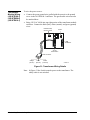
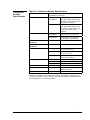
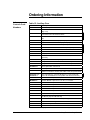
1
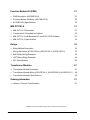
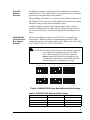
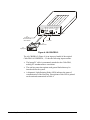
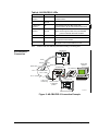
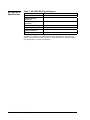
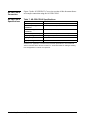
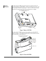
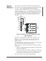
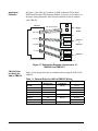
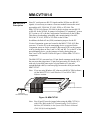
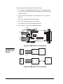
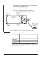
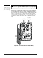
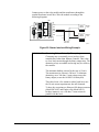
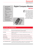
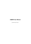
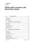
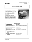
FANs 636.3, 1628.2 Auxiliary Gear Section Technical Bulletin Issue Date 0401 TECHNICAL BULLETIN Auxiliary Gear Introduction Page *3 Actuators 5 • M100C Actuator Description 5 • Wiring M100C Actuators • M100C Specifications *5 8 AS-CBLPRO-2 9 • AS-CBLPRO-2 Description *9 • AS-CBLPRO-2 Connection *11 • AS-CBLPRO-2 Specifications 12 AS-CBLCON-0 13 • AS-CBLCON-0 Description *13 • AS-CBLCON-0 Connection 14 • AS-CBLCON-0 Specifications 14 AS-CVTPROx00-0 *15 • AS-CVTPROx00-0 Description *15 • AS-CVTPROx00-0 Connection *17 • AS- CVTPROx0-00 Specifications *19 * Indicates those sections where changes have occurred since the last printing. © 2001 Johnson Controls, Inc. Code No. LIT-6363080 1 www.johnsoncontrols.com Function Module Kit (FMK) 21 • FMK Description (AS-FMK102-0) *21 • Function Module Kit Wiring (AS-FMK102-0) *25 • AS-FMK102-0 Specifications MM-CVT101-0 31 • MM-CVT101-0 Description *31 • Connection for Download and Upload • MM-CVT101-0 with Windows NT and HVAC PRO Software • MM-CVT101-0 Specifications 32 *33 34 Relays 35 • Relay Module Description 35 • Wiring the Relays (AS-RLY050-0) (AS-RLY100-1) (AS-RLY002-0) 36 • AHU Relay Wiring Examples 38 • UNT Relay Wiring Examples 43 • RLY Specifications *45 Transformer Modules 47 • Transformer Module Description 47 • Transformer Module Wiring (AS-XFR100-1) (AS-XFR050-0) (AS-XFR010-1) 48 • Transformer Modules Specifications 49 Ordering Information 51 • *51 Johnson Controls Code Numbers * Indicates those sections where changes have occurred since the last printing. 2 29 Auxiliary Gear—Auxiliary Gear Introduction This document describes accessories used with various Johnson Controls Application Specific Controllers (ASCs), such as the Air Handling Unit (AHU) controller, Unitary (UNT) controller, Variable Air Volume (VAV) controller, Variable Air Modular Assembly (VMA), DX-9100, TC-9100, XTM, and XT-9100. The accessories in this document include: • Actuators • AS-CBLPRO-2 • AS-CBLCON-0 • AS-CVTPROx00-0 • Function Module Kit (FMK) • MM-CVT101-0 • Relays • Transformer Modules Auxiliary Gear—Auxiliary Gear 3 4 Auxiliary Gear—Auxiliary Gear Actuators M100C Actuator Description Wiring M100C Actuators The M100C Series Motor Actuator is used in damper and valve applications where proportional control from a digital controller is required. The M100C communicates with AHU/UNT/VAV controllers depending on the position of the 8-pin DIP switch. 24 V COM ZBUS COM T1 24 V COM AHU/UNT Terminals 24 VAC PWR BUS Separate 24 VAC Transformer T2 M100C Motor with R81CAA-2 Board HVAC PRO™ software defines the address for the M100C. Zone Bus Address Switch O 1 2 3 4 5 6 7 8 N ahum100a Figure 1: M100 Motor Zone Bus Connection Using R81CAA-2 Board When you connect an M100C Actuator to the Zone Bus, its own 24 VAC (Volts Alternating Current) transformer must power it. Multiple M100s each require an individual transformer. The only connections between the AHU/UNT/VAV and M100C are from the ZBUS and COM terminals of the AHU/UNT/VAV to the BUS and COM terminals in the M100C. A separate 24 VAC transformer is required to power the M100C. Refer to Figure 1 for terminal locations when wiring an M100 Actuator. Note: Zone Bus address switch settings are determined by the controller configuration. The Zone Bus address is set to match the address assigned in the HVAC PRO software. Auxiliary Gear—Auxiliary Gear 5 ! CAUTION: Equipment Damage Hazard. Connecting the 24 VAC of the terminal block from the ASC (AHU, UNT, VAV) to the M100C can possibly damage the transformers. Switch Settings 1 2 3 4 5 6 7 8 OFF CW CCW COM T1 BUS T2 M100c09 Figure 2: Digital Circuit Board Make field adjustments using the 8-position DIP switch located on the cover-mounted circuit board as shown in Figure 12. The position of these switches specifies the operating parameters as shown in Table 1. Table 1: Switch Settings Switch Number On Function Off Function 1 Slave Master 2 S-curve Linear 3 Reverse Acting Direct Acting 4 Zone Bus L1 Bus (DSC 1000 product line) 5 Address Selection* Address Selection* 6 Address Selection* Address Selection* 7 Address Selection* Address Selection* 8 Address Selection* Address Selection* *Refer to the Master/Slave section in the M100C Series of Motor Actuators with Proportional Digital Control Signal Input and R81C Interface Board (LIT-121347) Technical Bulletin located in the Installation Sheets Manual (FAN 121) for complete address selection options. ! Zone Bus 6 CAUTION: Disconnect the electrical power supply before attempting to adjust the switch settings. AHU/UNT/VAV controllers use the Zone Bus. Set Switch 4 to the On position to allow up to eight zone actuators to communicate with the AHU/UNT/VAV controllers. Auxiliary Gear—Auxiliary Gear Zone Bus Address Selection An address is a numeric code that precedes a controller’s command to a controlled device. The controlled device will respond only to a command preceded by its assigned address code number. The positioning of Switches 5, 6, 7, and 8 provides address information to the controller. The switches are each positioned such that the sum of their individual values provides the desired address value. Configure multiple actuators with a separate address when each one performs a different function. When they all perform the same function, set one unit as the master, with the remaining units on that address set as slaves. AHU/UNT/VAV Controller Zone Bus Address Selection The Zone Bus addresses used by the AHU/UNT/VAV controller are 20 through 27. Make the address assignment during the HVAC PRO configuration process for Analog Outputs (AOs). Refer to the HVAC PRO User’s Manual (FAN 637 or 1637.5) for details. ! CAUTION: The phone jack connector on the terminal board is for easy, single-point connection of the HVAC PRO service device (laptop PC [Personal Computer]). Do not connect any other device at the phone jack. Connection of another device at the phone jack may result in damage to the equipment or wiring. 4 5 6 7 8 OFF 4 6 7 8 OFF 5 6 7 8 4 Address 23 5 6 7 8 OFF 5 6 7 OFF OFF 4 Address 21 Address 20 4 5 Address 22 8 4 5 6 7 8 OFF Address 24 Address 25 m100c13 Figure 3: AHU/UNT/VAV Zone Bus Address Switch Settings Table 2: AHU/UNT/VAV Address Switch Values Switch Number On Value Off Value 5 0 — 6 0 4 7 0 2 8 0 1 Auxiliary Gear—Auxiliary Gear 7 For selection of Zone Bus, Switch 5 must be On and an additional value of 20 added to the total of the switch settings. For example: to select L1 Address 25, set Switches 6 and 8 Off and Switches 5 and 7 On (25 = 0 + 4 + 0 + 1 from the switch settings and +20 because of Zone Bus selection). Use the switches to select any Zone address between 20 and 27. M100C Specifications Table 3: M100C Specifications Product M100C Motor Actuator Power Requirements 24 VAC at 50/60 Hz, 25 VA spring return, 20 VA non-spring return Rotation Timing 60 seconds for 160º travel 38 seconds for 90º travel Ambient Operating Conditions -40 to 52ºC (-40 to 125ºF), 90% RH non-spring return -37 to 52ºC (-35 to 125ºF), 90% RH spring return Ambient Storage Conditions -40 to 52ºC (-40 to 125ºF), 90% RH Dimensions (H x W x D) 143 x 111 x 125 mm (5.64 x 4.38 x 4.94 in.) Shipping Weight 4.1 kg (9 lb) Enclosure NEMA-1 Agency Compliance FCC, UL, CSA Agency Listing UL Recognized File E27734 Guide XAPX2 CSA Certified Temperature Indicating and Regulating Equipment The performance specifications are nominal and conform to acceptable industry standards. For application at conditions beyond these specifications, consult the local Johnson Controls office. Johnson Controls, Inc. shall not be liable for damages resulting from misapplication or misuse of its products. 8 Auxiliary Gear—Auxiliary Gear AS-CBLPRO-2 AS-CBLPRO-2 Description The AS-CBLPRO-2 (Cable PRO) is an interface device for use between a computer running Configuration Tools software and Application Specific Controllers (ASCs) or Lab and Central Plant (LCPs) controllers. Exceptions to these are the DX-9100, TC-9100, XT-9100, XTM, and DT-9100. It is used for downloading, uploading, or commissioning a configuration via the Zone Bus communication port on the controller. When used with a Zone Bus device, such as the ASC or Zone Terminal Unit (ZTU), the Cable PRO is strictly an electrical interface between the serial RS-232 port of the computer and the Zone Bus. The Cable PRO uses either a 6-pin to 8-pin cable or a 6-pin to 6-pin cable to connect to an AHU, VAV, and UNT. The Cable PRO operates on 24 VAC drawn from the controller over the wire used to make the Zone Bus connections. The data rate on both the RS-232 and the Zone Bus is 1200 baud. The connection to the RS-232 COM port of the computer is by means of a DB9 or DB25 connector supplied with the AS-CBLPRO-2. After connecting it, make sure the Cable PRO is 0.3 meters (1 foot) or more away from the computer monitor and system unit. IMPORTANT: Do not position the Cable PRO near the computer monitor or Personal Computer (PC). Communication can be disrupted by the electromagnetic noise emitted from that equipment. Auxiliary Gear—Auxiliary Gear 9 Zone Bus ZB LCP LCP-100 Ext. Power LED LED Service Port 12 vac/vdc cblpro1 To Controller, Zone Terminal, Zone Sensor To Power To Service Port To Laptop PC Figure 4: AS-CBLPRO-2 The AS-CBLPRO-2 (Figure 4) is an improved model of the original Cable PRO AS-CBLPRO-0, -1. It has the following improvements: 10 • The laptop PC cable is permanently attached to the Cable PRO, making PC attachment more convenient. • The unit has protection against earth ground faults that may be introduced into the system. • A diagnostic Light-Emitting Diode (LED) indicates the status of communication of the Zone Bus. Descriptions of this LED is printed on the unit and summarized in Table 4. Auxiliary Gear—Auxiliary Gear Table 4: AS-CBLPRO-2 LEDs ZB LED LCP LED Normal and Fault Conditions 2 Flashes per Second Off Connected to the Zone Bus Normal Communication Off 2 Flashes per Second Connected to the LCP Normal Communication 1 Flash per Second Off Connected to the Zone Bus via RS-232 Communication, or 24 VAC Shorted to Zone Bus 5 Flashes per Second 5 Flashes per Second 24 VAC High Side Shorted to Earth Ground Note: Remove ground fault and cycle CBLPRO power to eliminate this fault condition. On Off Controller Common Shorted to Zone Bus Off On LCP Common Shorted to LCP Data Terminal or Interrupted Communication Off Off No Power or No Connection to Active Zone Bus or No Power or No Communication for LCP Note: With the VMA, the LEDs only flash when sending or receiving data. Transformer AS-CBLPRO-2 Connection Green Orange Brown Splice Here Pin 3 = COM ZONE UNT SENSOR VAV 6 AHU Pin 2 = 24 VAC 6-pin RJ12 Phone Plug 12 3 45 6 ZONE BUS 24 VAC 24 VAC COM ZONE BUS Molex Connector HVAC PRO Software DOWN LOAD Pin 1 24 VAC Splice Here Reset Button AS-CBLCON-0 AS-CBLPRO-2 ZB LCB LCP-100 Ext. Power ZoneBus LED LED ServicePort 12 vac/vdc ZT CBLPRO Zone Terminal Switch must be in download position. ALARM cblconnect Figure 5: AS-CBLPRO-2 Connection Example Auxiliary Gear—Auxiliary Gear 11 AS-CBLPRO-2 Specifications Table 5: AS-CBLPRO-2 Specifications Product AS-CBLPRO-2 Power Requirements 24 VAC from controller Ambient Operating Conditions N/A (Test equipment only) Ambient Storage Conditions -18 to 50ºC (0 to 120ºF) Dimensions (H x W x D) 33.2 x 94 x 159 mm (1.3 x 3.7 x 6.25 in.) Shipping Weight 0.63 kg (1.38 lb) Agency Compliance N/A Agency Listing N/A The performance specifications are nominal and conform to acceptable industry standards. For application at conditions beyond these specifications, consult the local Johnson Controls office. Johnson Controls, Inc. shall not be liable for damages resulting from misapplication or misuse of its products. 12 Auxiliary Gear—Auxiliary Gear AS-CBLCON-0 AS-CBLCON-0 Description The AS-CBLCON-0 Cable Connector (Figure 6) is a cable connecting device that accepts the different sizes of telephone cable connectors used with the controller products so that they are able to communicate. It also monitors Zone Bus communications to the ASC or ZTU by red and green Light-Emitting Diodes (LEDs) described in Table 6. It has a terminal strip and a ZT download switch. To download the ZTU, slide the switch on the AS-CBLCON-0 to the download position. The red LED is indication of 24 VAC power. The green LED shows Zone Bus transmissions from the controller. If the green LED is off, the Zone Bus wire is open. If this LED is on solid, the Zone Bus is shorted to Common. For details, refer to the Zone Terminal Technical Bulletin (LIT-6363014 or LIT-1628330) in FAN 636.3 or 1628.2. The AS-CBLCON-0 also extends the ZTU from 15.2 m (50 ft) to 154.2 m (500 ft) with 18 AWG wire size. Table 6: AS-CBLCON-0 LEDs Red LEDPower Green LED– Comm Cause OFF OFF No power to controller ON OFF Zone Bus wire open ON ON Zone Bus wire shorted to Common or CBLCON-0 switch in download position ON Blinking Normal communications ZONE UNT SENSOR VAV 8 6 AHU 8 ZONE BUS 24 VAC ZONE BUS DOWN LOAD 24 VAC COM 6 6 ZT CBLPRO Green LED Red LED cblcon Figure 6: AS-CBLCON-0 LEDs Auxiliary Gear—Auxiliary Gear 13 AS-CBLCON-0 Connection Figure 5 in the AS-CBLPRO-2 Connection section of this document shows an example connection using the AS-CBLCON-0. AS-CBLCON-0 Specifications Table 7: AS-CBLCON-0 Specifications Product AS-CBLCON-0 Power Requirements N/A (No active circuits, only indicators.) Ambient Operating Conditions 0 to 50ºC (32 to 120ºF) Ambient Storage Conditions -40 to 60ºC (-40 to 140ºF) Dimensions (H x W x D) 31.8 x 47 x 73.7 mm (1.85 x 1.25 x 2.90 in.) Shipping Weight 0.163 kg (0.36 lb) Agency Compliance N/A Agency Listing N/A The performance specifications are nominal and conform to acceptable industry standards. For application at conditions beyond these specifications, consult the local Johnson Controls office. Johnson Controls, Inc. shall not be liable for damages resulting from misapplication or misuse of its products. 14 Auxiliary Gear—Auxiliary Gear AS-CVTPROx00-0 ASCVTPROx00-0 Description The AS-CVTPROx00-0 Zone Bus/N2 Bus Interface Converter serves as a converter between room sensors/controllers communicating over the Zone Bus or N2 Bus and a user interface. The interface is either a Palm III family compatible handheld device or a PC. Notes: An adapter is required to use Palm V devices. The Dock V PRO adapter is available from Solvepoint Corporation at www.palmdock.com and local retailers. Other Palm models have not been fully tested with the CVTPRO and should not be used. The CVTPRO Zone Bus/N2 Bus Interface converter comes complete with four connection cables. There are two external power options available for N2 communication: 120 VAC to +3 VDC (Volts Direct Current) adapter (included with the CVTPRO in North America) and 2 AAA batteries (not included). The CVTPRO is proven to be compatible with TC-9102’s, AHUs, VAVs, UNT1xxs, VMA 12x0/14x0 Series controllers, UNT1100s, TMZs, TE-6x00 sensors, GX-9100 tools, DX-9100 tools, DT-9100 displays, XTMs, and Network Dialer Modules (NDMs). CVTPROs work with VMA Balancing Tool (VBT) software for the VMA1200 and VMA1400; Windows 98 and Windows NT, and Palm Operating System (OS) Version 2.x or later. The CVTPRO converter is not compatible with the Zone Terminal Unit (ZTU). See the AS-CVTPROx00-0 Zone Bus/N2 Bus Interface Converter Technical Bulletin (Part No. 24-9544-0) (shipped with the product) for specific interoperability information. Auxiliary Gear—Auxiliary Gear 15 Physical Description The back of the CVTPRO converter has ports for connection with a PC (via the Rigid Metal Conduit [RMC] –9 port), incoming power source, and the Zone Bus/N2 Bus RJ11 jack (Figure 7). This view also shows the back of the RS-232 connector that slides into the Palm device or adapter. RS-232 Connector to Palm III Device or Adapter for Palm V Zone Bus/ N2 Bus Port RJ11 Jack 6-Pin PC Port Power Input cvtdorsal Figure 7: Back of CVTPRO The front of the CVTPRO converter shows another view of the RS-232 connector (Figure 8). The Light-Emitting Diodes (LEDs) display the status of the unit relative to the field device. RS-232 Connector to Palm III Device or Adapter for Palm V Device Yellow LED (Receiving) Green LED (Transmitting) Red LED (Power) Battery Cover cvtfront Figure 8: Front of CVTPRO 16 Auxiliary Gear—Auxiliary Gear Figure 9 shows the terminations of the 6-pin phone cable used by the CVTPRO for N2 Bus communication. For Zone Bus communication, always use standard Zone Bus cables. Blue (N2+) White (N2-) Red (N2 REF) phonewire Figure 9: N2 6-Pin Phone Cable Terminations Figure 10 is a diagram of the connections possible between the CVTPRO and other devices. Refer to Table 9 for more information on the cables used with the CVTPRO. Palm III or Adapter for Palm V * CA LC N S P PL IC AT IO 2 abc d e ME N U 3 R A *Notes: Do not connect the CVTPRO to the Palm device and the laptop or PC at the same time. 1 ASCVTPROx00-0 Connection UL AT O TE-6x00/TMZ Room Sensor RJ11 Jack, 6-Pin 4 5 F IND Unplug the Palm device from the CVTPRO when not in use to conserve battery power. RS-232 Port CVTPRO Compatible Controller External Power Source or or Zone Bus/ N2 Bus Port RJ11 Jack 6-Pin DB9 Port Personal Computer * Zone Bus N2 Bus RJ45 Jack, 8-Pin N2 Bus Interface, 4-Pin N2 Socket/ 3-Pin N2 Plug with Tab and Extra 4-Pin N2 Socket cvtschematic Figure 10: Overview of Possible CVTPRO Connections Auxiliary Gear—Auxiliary Gear 17 Compatibility The following table lists compatible tools, OSs, and controllers used over the Zone Bus and N2 Bus with the CVTPRO converter. Table 8: Compatibility Chart Tool Bus OS Compatible Controller HVAC PRO Software Release 8.01 N2 Bus Windows 98SE, Windows NT Zone Bus Windows 98SE AHU1xx UNT1xx UNT11xx VAV10x VMA14x0 TMZ1600 VBT1400 Zone Bus Palm III or V (with adapter) with OS Version 2.x or later VMA14x0 VBT1200 Zone Bus Palm III or V (with adapter) with OS Version 2.x or later VMA12x0 GX-9100 N2 Bus Windows 98SE, Windows NT DT-9100 DX-9100 XP91xx XTM-905 (XPx-xxx) XT9100 DX-9100 Configuration Tool N2 Bus Windows 98SE, Windows NT DX-9100 XTM Configuration Tool N2 Bus Windows 98SE, Windows NT XTM-105 (XPx-xxx) NDM Configuration Tool N2 Bus Windows 98SE, Windows NT NDM Note: The CVTPRO converter is not compatible with Zone Terminal Units (ZTUs) at this time. For ZTUs, use the CBLPRO-2 converter. 18 Auxiliary Gear—Auxiliary Gear Cables ASCVTPROx0-00 Specifications Table 9: Cables Included with the CVTPRO To Connect the CVTPRO to This… Use the Cable with These Terminations: PC DB9 and RMC-9 (457 mm [18 inches]) Palm III Compatible Device No cable needed Controller via the Zone Bus 8-pin RJ45 and 6-pin RJ11 phone cable (1.8 mm [6 ft]) Controller via the N2 Bus 4-pin N2 socket/3-pin N2 plug with tab and 6-pin RJ11 phone cable (1.8 m [6 ft]) Note: Extra CVTPRO 4-pin N2 socket required for older AHUs and similar devices. TE-6x00/TMZ Room Sensor via the Zone Bus 6-pin and 6-pin RJ11 phone cable (1.8 m [6 ft]) Table 10: General Specifications for the AS-CVTPROx00-0 Zone Bus/N2 Bus Interface Converter Feature Specifications Power Zone Bus: Controller or thermostat (+15 VDC [Volts Direct Current] or 24 VAC) N2 Bus: External Adapter 120 VAC to +3 VDC 200 mA (milliamperes) (included with CVTPRO converter in North America), or Batteries (2 AAA) (not included) Ambient Operating Temperature 0 to 50°C (32 to 122°F) Ambient Operating Humidity 20-80% RH (Relative Humidity) 30°C (86°F) maximum dew point Ambient Storage Temperature -40 to +60°C (-40 to 140°F) Ambient Storage Humidity 5-95% RH 30°C (86°F) maximum dew point Battery 2 AAA batteries Battery Life Approximately 7.5 hours Serial Interfaces DB-9 PC Port for RS-232 Connector Zone Bus/N2 Bus RJ11 Jack (6-Pin) Dimensions (H x W x D) 79.38 x 60.33 x 22.23 mm (3.125 x 2.375 x 0.875 in.) Shipping Weight 0.227 kg (0.5 lb) Agency Listings UL listed and CE Mark Agency Compliance UL 916, UL 864 Plastic housing meets UL 94-5V CSA 22.2 No. 205 FCC Part 15, Subpart B, Class A CE Mark: EN50081-1 (Electromagnetic Compatibility, EN55011, Class B) EN50082-2 (Electromagnetic Compatibility, EN61000-3-2 and EN61000-3-3) Auxiliary Gear—Auxiliary Gear 19 20 Auxiliary Gear—Auxiliary Gear Function Module Kit (FMK) FMK Description (AS-FMK102-0) The Function Module Kit (FMK) provides the enclosure and termination board to connect up to four, single-slot function modules to the AHU. FMK Mounting Procedures Two different mounting position options (UPM or perpendicular) are available when installing the FMK102 Function Module Kit. Built-in screw holes are provided for mounting the unit in the angled position. These holes are compatible with the Universal Packaging Module (UPM) enclosure. Use perpendicular mounting when replacing the FMK100 or in confined areas on various surfaces. Note: Versions previous to the FMK102 are not supported in the UPM. Angle Mounted FMKs 222.3 mm (8-3/4 in.) Exterior FM 146.0 mm (5-3/4 in.) Exterior Angled Position FM 198.4 mm (7-13/16 in.) Exterior 158.8 mm (6-1/4 in.) Exterior Perpendicular Position ahu103c Figure 11: FMK Mounted in AHU103 Auxiliary Gear—Auxiliary Gear 21 FMK Mounting Holes Write-on FM Identification Labels Velcro ® Mounting Pad Pull-Off Cover Screw Terminals Wiring Terminal Cover fmk1 Figure 12: Function Module Kit Refer to Figure 12 and follow the steps below when installing an FMK102 into the UPM or mounting in the horizontal position. 1. Remove all Function Modules (FMs) from the FMK102. The mounting holes are accessible through this area. 2. Position the FMK in the desired area of the UPM. Align the small end of the slotted mounting holes in the FMK with the grid pattern holes in the UPM. Mark these holes to reference the mounting area. Note: Ensure your selected mounting position will not interfere with door closure. 22 3. Set the FMK aside and install the two provided mounting screws in the desired holes. Insert the screws so there is approximately 1/2 inch thread visible. 4. Install the FMK mounting slots over the mounting screws. Slide the FMK into place. Position the screws at the small end of the slot. Tighten the screws to secure the FMK102. 5. When you have completed mounting the FMK102, you may go on to wire the unit. Remove the wiring cover, to access the wiring terminals, by firmly pulling the cover away from the unit. To reinstall the cover, align the cover and the unit and press firmly into place. Auxiliary Gear—Auxiliary Gear Function Modules (FMs) The types of FMs provided for use in the FM kit are: Input: The input FMs consist of the FM-IAP and various models of the FM-IDP modules. Each occupies one slot in the FM kit. ● Output: The output FM (FM-OAP) has the same dimensions as the input FMs except it has twice the width. Therefore, the output FM occupies two slots in the FM kit. An FM-OAP102 Pneumatic Manual Module must be ordered with each FM-OAP103 Electronic Module. ● Perpendicular Mounting and FMK100 Replacement The FMK102 cannot be mounted on a DIN rail. Therefore, when you replace a DIN rail mounted FMK100, you must remove the DIN rail or install 1/4 inch mounting spacers so the FMK102 clears the DIN rail. Refer to Figure 13 and follow the steps below when mounting an FMK102. Plastic Latch Zone Connection FMK Mounting Base Pull-Off Cover Wiring Terminal Cover Pull Out Circuit Board MtFMK Figure 13: Mounting the FMK To mount the FMK perpendicular on a wall or in an enclosure: 1. Remove the wiring terminal cover, pulling it off the unit (Figure 13). 2. Remove the printed circuit board from the unit by simultaneously pressing down on the plastic latch and pulling the board out of the unit. Auxiliary Gear—Auxiliary Gear 23 3. Determine the required anchors and mounting screws for the mounting surface. Use three or four size No. 8 to No. 12 mounting screws. Note: Ensure the screw heads do not interfere with the FMK printed circuit board. 24 4. Position the FMK so there is clearance to install the FMs and wire the terminals. Refer to Figure 11 for dimensions. 5. Drill four holes in the corners of the FMK base. Remove the FMK and install the wall anchors if required. Reposition the FMK frame over the mounting holes and install the screws. 6. Reinsert the printed circuit board into the FMK frame. Ensure the board aligns into the guide slots and that the wiring terminals face the front of the unit. Push the board into the FMK until the plastic latch snaps into the board. Auxiliary Gear—Auxiliary Gear Function Module Kit Wiring (AS-FMK102-0) AHU100 Termination Board AO1 AOCOM AO 2 AHU100 AO 3 Analog AOCOM AO 4 Outputs AO 5 AOCOM AO 6 AO 2 Controls FM-OAP103 in Slots C and D FM-OAP103 J2 FM-OAP102 TB2 + A B+ + C + D - FM-OAP103 J3 FM-OAP102 J4 AS-FMK102-0 fmkwir Figure 14: AO1/AO2 Controlling Two FM-OAP103 Function Modules Refer to Figure 14 for terminal locations when using two FM-OAP103-0s with the FMK. The FM-OAP 103-0 must use adjacent Slots A-B or C-D in the FMK-102-0. Note: Do not insert the FM-OAP 102/103 module into the two middle slots (B and C) of the FMK. Refer to Table 8 for slot allocation. ● ● either hardwire the FMK termination block Terminal B of the FMK for the top OAP module and hardwire terminal block Terminal D on the FMK for the bottom OAP or, use the 0.9 m (3 ft) AS-CBL100-0 Quick Connect Cable to connect consecutive AOs (for example, AO1 and AO2) to both FM-OAP103-0 transducers by connecting the center connector (J3) on the FMK. Refer to Figure 15 for terminal locations when using one FM-OAP-103/102 with the FMK. Refer to Table 8 for slot allocation. ● either hardwire from the AS-AHU100 Analog Output Terminal Block—if the FM-OAP103/102 is installed in the top half (Slot AB) of the FMK, use Terminals B+ and B- on the FMK. Use Terminals D+ and D- if the FM-OAP103/102 is installed in the bottom half (Slot CD) of the FMK. The B+ or D+ connect to AO-n. The B- or D- connects to AOCOM Auxiliary Gear—Auxiliary Gear 25 or, use an AS-CBL100 Quick Connect Cable to connect the odd numbered AOs to the top quick connector (J2) of the FMK with the FM-OAP103/102 in Slots A and B. The next even numbered analog output is available for termination elsewhere. Use the bottom quick connector (J4) of the FMK with the FM-OAP in Slots C and D for even numbered AOs. The previous odd numbered analog output is available for termination elsewhere. For example, if you plug a CBL100 into AO3 and AO4, and into J4 of the FMK, then AO4 controls the OAP in Slot C and D. AO3 is available for hardwiring to another device. ● AHU100 Termination Board AO1 AOCOM AO 2 AO 3 AOCOM AO 4 AO 5 AOCOM AO 6 AHU101 Analog Outputs VDC AI1 AICOM AI 2 AI 3 AICOM AI 4 AI 5 AICOM AI 6 AI 7 AICOM AI 8 VDC AHU101 Analog Inputs Unregulated 30 VDC Power Supply AO 1 Controls FM-OAP103 in Slots A and B FM-OAP103 J2 FM-OAP102 TB2 + A + B + C + D - FM-IAP101 J3 FM-IAP101 J4 AS-FMK102-0 fmkwirqc Figure 15: Single AO Controlling FM-OAP103/102 with AS-CBL100 and Hardwired Input Function Modules ! CAUTION: The FM-IDP or FM-IAP uses the 30 VDC unregulated power supply. This supply voltage must be connected to a positive (+) terminal corresponding to the FMK slot holding the function module. Reversing this connection will damage the AS-AHU100 electronic board. When using FM-IDP or FM-IAP modules, the AS-AHU102 will continually reset if you forget to install the current (C) jumper for the appropriate Analog Input (AI). 26 Auxiliary Gear—Auxiliary Gear Wiring Input (FM-IAP and FM-IDP) Modules Refer to Figure 16 for terminal locations when wiring input modules. Wire from the +VDC terminal on the AHU controller board to either the A+, B+, C+, or D+ terminal on the FMK. All four terminals are electrically connected on the FMK. Wire from each AI terminal on the controller board to the A-, B-, C-, or D- terminal on the FMK. Set the AI jumper on the AHU102 board to the current (C) position. One +VDC wire is sufficient per FMK, but it must be run in the same bundle as the AI wires and be large enough to carry current for all four inputs (80 mA maximum). AHU100 Termination Board 24 V COM ZBUS BI 1 BICOM BI 2 BI 3 BICOM BI 4 BI 5 BICOM BI 6 BI 7 BCOM BI 8 24 VAC COM ZBUS HAND A+ J2 Function Module Slots J3 B+ +VDC C+ D+ J4 AS-FMK102-0 Fmkwirzb Figure 16: Zone Bus Connection with Manual Override Status Indication Wire the 24V, COM, and ZBUS terminals from the AHU100 to the FMK102 to connect the Zone Bus from the AHU controller to the FMK102. You can use this common for the Hand/Manual Override Indicator Common. The Hand/Manual Override Binary Indicator can be connected to a Binary Input (BI) and BICOM on the AHU controller board. Refer to Figure 16 for terminal locations when monitoring Auto-Manual switch status. 1. Hardwire from the Hand terminal on the FMK102 to a BI point on the AHU100 controller board. 2. Hardwire from COM on the FMK102 to COM on the AHU100 if you use the Zone Bus. Hardwire from COM on the FMK102 to BICOM on the AHU100 controller board if you do not use the Zone Bus. Note: Refer to Table 11 for complete wiring information. Auxiliary Gear—Auxiliary Gear 27 Application Examples In Figure 17 the AHU AI-1 connects to FMK connector CD for Input Differential Pressure (IDP) Function Module. Likewise, AI-2 connects to the Input Analog Pneumatic (IAP) Function Module in Slot D with the same CBL100. A AHU100-0 AS-CBL100 Cables RLY050 or RLY002 B BO1 and 2 AB AO1 and 2 OAP 1 Slot A B OAP 2 C D OAP 3 Slot A B BD CD AO3 and 4 AB AI1 and 2 BD IDP CD IAP FMK100-1 or FMK102-0 FMK102-0 C D Jumper AI1 and 2 for current. AHU101A Figure 17: Application Example--Interconnect of AHU100-0 to FMK102-1 CBL100 Rules for Wiring the AHU to FMK102 Table 11 lists the general rules to remember when wiring the AHU to the FMK102. Table 11: General Rules for AHU to FMK102 Wiring Function Module IDP/IAP Function Module Slot FMK Cable 100 Connector AHU Point A AB (J2) AI Even CD (J4) AI Odd IDP/IAP B IDP/IAP C AI Odd IDP/IAP D OAP103 AB AB (J2) AO Odd * AI Even OAP103 AB BD (J3) AO Odd OAP103 CD OAP103 CD CD (J4) AO Even* AO Even * You can separately hardwire the other output to another device. 28 Auxiliary Gear—Auxiliary Gear Pneumatic Connection For complete information on installing pneumatic function modules, refer to the Output Analog Pneumatic (OAP) Technical Bulletin (LIT-636045) in the Metasys Network Technical Manual (FAN 636). AS-FMK102-0 Specifications Table 12: AS-FMK102-0 Specifications Product AS-FMK102-0 Power Requirements None (supplied by controller) Ambient Operating Conditions 32 to 122°F (0 to 50°C) Ambient Storage Conditions -40 to 158°F (40 to 70°C) Dimensions (H x W x D) 146 x 114 x 156 mm (5.75 x 4.5 x 6.13 in.) Shipping Weight 2 lb Agency Compliance UL 916, UL 864, CSA C22.2-205 Agency Listing UL Listed and CSA Certified as part of Metasys Network. The performance specifications are nominal and conform to acceptable industry standards. For application at conditions beyond these specifications, consult the local Johnson Controls office. Johnson Controls, Inc. shall not be liable for damages resulting from misapplication or misuse of its products. Auxiliary Gear—Auxiliary Gear 29 30 Auxiliary Gear—Auxiliary Gear MM-CVT101-0 MM-CVT101-0 Description Since PC serial ports use RS-232 signals and the N2 Bus uses RS-485 signals, it is necessary to connect a converter module between the serial port and the ASC, DX-9100, TC-9102, XTM, or XT-9100. The MM-CVT101-0 (in Europe, IU-9100) is the device that converts RS-232 to RS-485 for the N2 Bus. It connects a Facilitator/Companion system PC Version or a PC with the Configuration Tools directly to the N2 Bus. This allows downloading, uploading, and commissioning of an ASC, DX-9100, TC-9102, XTM, or XT-9100 via the N2 Bus. In addition, the End-of-Line (EOL) termination jumpers for the PC Version Companion system are located in the MM-CVT101-0 N2 Bus converter. To set the PC as the terminating device as required for the Companion system or for the second N2 Bus on an NCM, set the jumpers to In by placing them on Pins 1 and 2 of W1 and W2. To set the PC as the non-terminating device, set the jumpers to Out by placing them on Pins 2 and 3 of W1 and W2. Refer to Figure 19 for the MM-CVT101-0 components. The MM-CVT101 converter has a 25-pin female connector on the body of the converter that plugs-into a 25-pin serial port on the PC directly. PCs with only 9-pin serial ports require a 9-pin female to 25-pin male straight through cable (or converter plug) between the serial port and the MM-CVT101. Note: If you are using Windows NT software with HVAC PRO software, see the MM-CVT101-0 with Windows NT and HVAC PRO Software section. 25-pin Female Connector Plug End to 120 VAC Power Supply Mmcvt101 Figure 18: MM-CVT101 Note: Pins 20 and 22 must be jumped when using the MM-CVT101-0 with LCPs. Refer to the LCP Commissioning Tool Technical Bulletin (LIT-636069e) in the System 9100 Technical Manual (FAN 636.4) for wiring details. Auxiliary Gear—Auxiliary Gear 31 Refer to Figure 19 for illustration of the following: • J1: Jumpers for changing the transmit/receive communication of Pins 2 and 3 on the 25-pin Electronic Industries Association (EIA) female connector • P1: 25-pin female connector for connection to a PC (via cable or direct) • P2: Screw terminal for trunk connections • P3: Screw terminal for power connections • W1: Jumper (1) for EOL termination (In/Out) • W2: Jumper (1) for EOL termination (In/Out) Resistor COM P3 9V Power Light Capacitor 1 2 3 4 2 W1 J1 321 W2 N2+ P1 P2 N2- 3 1 REF mmcvt_tpvw Resistor Figure 19: MM-CVT101-0 Components Connection for Download and Upload AHU VAV UNT VMA N2 + REF N2 - N2 - REF REF CVT PC CVT Cable N2 Bus DX TC XTM RT + N2 + RT - N2 - COM REF PC CVT Figure 20: MM-CVT101-0 Connections 32 Auxiliary Gear—Auxiliary Gear MM-CVT101-0 with Windows NT and HVAC PRO Software HVAC PRO software (Release 7.03 or later) running on Windows NT operating system does not support the MM-CVT101 converter for direct connections to the N2 Bus. Solution: B & B Converter Replace the MM-CVT101-0 converter with the B & B Electronics converter and power supply shown in Table 13. These parts are available from: Windows NT system does not create the proper Request to Send (RTS) signal for Johnson Controls devices. Without the proper RTS signal, N2 Bus communication is not established and downloading fails. B & B Electronics 707 Dayton Rd. P.O. Box 1040 Ottawa, IL 61350 Phone: (815) 433-5100 www.bb-elec.com See the footnote under Table 13 for special ordering instructions. Table 13: B & B Electronics Products and Model Numbers B & B Electronics Product Model Number RS-232 to RS-485 Converter 485TBLED* RS-232 to RS-485 Power Supply for Converter • 485PS2 N2 devices require a faster converter turnaround time. Resistor R9 must be changed from the standard 100K ohm to a 68K ohm, 1%, 1/8 watt resistor. B & B Electronics provides the change for a $15 charge. Request a “modification line item: change R9 to a 68K ohm, 1% resistor” when placing your order. The B & B converter uses the same cable as the MM-CVT101 to connect to the PC. The B & B converter has two jumpers (see Figure 21). Several changes are required for use with Johnson Controls N2 devices. The B & B converter has separate connections for the transmitting and the receiving N2 lines (see Figure 21). These connections must be connected together to provide a 3-wire communication trunk. Setting up the B & B converter for use with Johnson Controls N2 devices: 1. Using Figure 21, insert one jumper in the CONTROL SD location and insert the other jumper in the ECHO OFF location. The SD position causes a timed internal RTS signal to be generated when the TD signal is active. 2. Insert an external 100 ohm resistor between the GND terminal and the N2 cable reference wire. Note: The external power supply common is also connected to the GND terminal. No connection is made to the FR GND SHIELD terminal on the B & B converter. Auxiliary Gear—Auxiliary Gear 33 3. Connect terminals TD(A) and RD(A) together with an external jumper wire to form the N2- line connection point. 4. Connect terminals TD(B) and RD(B) together with an external jumper wire to form the N2+ connection point. Note: the B & B converter does not have provisions for an End-of-Line Resistor (EOLR), therefore increased Retries and Offlines occur. TB1 B & B Electronics Model 485TBLED FR.GND SHIELD TD(A) TD(B) RD(A) N2N2+ REF. RD(B) GND +12VDC 100 ohm R9 C6 ECHO CONTROL OFF RTS ON SD 485PS2 bbcvt Figure 21: B & B Electronics Converter and Power Supply MM-CVT101-0 Specifications Table 14: General Specifications Product MM-CVT101-0 RS-232 to RS-485 Protocol Converter Power Requirements 9 VDC transformer that plugs into a 120 VAC wall outlet Ambient Operating Conditions 0 to 50ºC (32 to 120ºF) 10 to 90 % non-condensing relative humidity Ambient Storage Conditions -40 to 70°C (-40 to 158°F) Dimensions (H x W x D) 25.4 x 53.3 x 114 mm (1.0 x 2.1 x 4.5 in.) Shipping Weight 0.54 kg (1.2 lb) The performance specifications are nominal and conform to acceptable industry standards. For application at conditions beyond these specifications, consult the local Johnson Controls office. Johnson Controls, Inc. shall not be liable for damages resulting from misapplication or misuse of its products. 34 Auxiliary Gear—Auxiliary Gear Relays Relay Module Description The relay module is a self-contained relay device that provides an interface between the 24 VAC, low voltage (input) triac circuitry and the 240 VAC 5 ampere line-voltage (output) devices. These relays are used when the triac output is not compatible with the device or the device exceeds the load rating of the triac. AS-RLY050-0 AS-RLY100-1 The AS-RLY050-0 and AS-RLY100-1 are primarily used with application specific controllers or in applications that require a metal relay enclosure. AS-RLY050-0 has two 24 VAC relays. AS-RLY100-1 has four 24 VAC relays. Both come with enclosures. AS-RLY002-0 The AS-RLY002-0 is the same relay module used in the AS-RLY050-0 and AS-RLY100-1. You can use the AS-RLY002-0 as a replacement board for either of these modules. The AS-RLY002-0 has two 24 VAC relays. AS-RLY050-0 AS-RLY100-1 AS-RLY002-0 relays Figure 22: Relay (RLY) Modules Position the relay module remotely next to the line-voltage device on the DIN rail. The enclosure can be mounted with DIN rail or directly mounted to a wall. The enclosure supports multiple 3/4 in. and 1-1/2 in. conduit connections. Remote Relay Enclosure Position the Remote Relay Enclosure (RLY050/100) as close as possible to the devices it operates. The Remote Relay Enclosure measures H x W x D 173 x 186 x 124 mm (6-13/16 x 7-5/16 x 4-7/8 in.). Auxiliary Gear—Auxiliary Gear 35 Wiring the Relays (AS-RLY050-0) (AS-RLY100-1) (AS-RLY002-0) ! CAUTION: Possible Equipment Damage or Electrical Shock. Disconnect power circuit before wiring Relay Kit. Refer to Figure 14 when wiring a AS-RLY002-0. To ensure separation of line and control wiring, route all low voltage wiring from the controller on the left-hand side of the UPM and route all line-voltage wiring to the righthand side as shown in Figure 23. Connect control and binary feedback wires according to the examples in Figure 24. For ease of wiring, use the AS-CBL100-0 with the AHU when the AHU is within three feet of the relay. Low Voltage Wiring Conduit Line Voltage Conduit from 120 VAC Supply Power Supply/ Transformer AHU100 Termination Board Relay Module AHU102 Controller Board FM Kit Zone Terminal AHU103 Figure 23: Low Voltage and Line-voltage Wiring 36 Auxiliary Gear—Auxiliary Gear Tables 3 and 4 describe the relay terminals for low voltage and line-voltage wiring. Table 15: Wiring Terminals-Low Voltage Relay Terminal Description A or C Relay control, switched 24 VAC from Binary Output (BO) (odd number BO using CBL100) B or D Relay control, switched 24 VAC from Binary Output (even number BO using CBL100) Coils Relay coil supply, connected to both relay coils (typically 24 VAC) Triacs Triac voltage common, used to energize Relay in Hand switch position Hand Binary contact feedback, closed indicates when HOA relay switch is in the Hand position Off Binary contact feedback, closed indicates when either HOA switch is in the Off position HOA Com Binary Input common for Hand/Off feedback Table 16: Wiring Terminals-Line-voltage (240 VAC 5 Ampere Maximum) Relay Terminal Description COM Common Relay Contact NC Normally Closed Relay Contact NO Normally Open Contact Auxiliary Gear—Auxiliary Gear 37 AHU Relay Wiring Examples AS-AHU100 (or VAV) BO 1 24 V BO 2 A Motor Starter COM NC NO A B COILS TRIAC BI 7 BICOM BI 8 B COM Motor Starter NC HAND OFF HOA COM NO L1 120/220 VAC AS-RLY050-0 / AS-RLYOO2-0 A BO 1 24 AC BO 2 AS-CBL100 A B BO 5 24 AC BO 6 B AS-AHU100 C C D BI 7 BICOM BI 8 D HAND OFF HOA COM AS-RLY100-1 / AS-RLY002-0 RLYDIA2 Figure 24: Relay Wiring Examples 38 Auxiliary Gear—Auxiliary Gear L2 Connect power to the relay module and the transformer through the conduit knockouts in each box. Wire the module according to the following diagrams. TB1 A COM NC Motor Starter Supply Fan Motor Starter Return Fan NO B COM NC NO L1 L2 120 VAC 220 VAC rlywirhv Figure 25: Starter Interlock Wiring Example IMPORTANT: Chattering Relays Driven By Binary Outputs-Chattering may occasionally occur in relays from manufacturers other than Johnson Controls. This is due to a low load current through the binary output triac. The chattering relays are audible and arcing may be visible at the contacts. The minimum holding current for the triac is 50 mA. The maximum triac current is 500 mA. To eliminate chattering, use a 360 ohm, 5-watt resistor across the binary output (or use the AS-RLY100 Relay Kit). There have been a few instances where loads have met the 50 mA current requirements, but still chattered. To date, the exceptions are Honeywell damper actuator (Model MC6161) and Finder relay (Model 60.12). In these instances, use a 1K ohm, 2-watt resistor in parallel with the load. Auxiliary Gear—Auxiliary Gear 39 AS-AHU100 BO 1 24 V BO 2 A COM NC NO A B COILS TRIAC BI 7 BICOM BI 8 B COM NC HAND OFF HOA COM NO AS-RLY050-0 / AS-RLY002-0 ahurly Figure 26: Wiring Example--AHU to RLY050 or RLY002 Important points to remember while wiring relays: ● ● ● ● Separate low voltage and line wiring, with line-voltage on the right. Hand operation using the H/O/A switch requires 24 VAC to the COILS terminal and COM to the TRIAC terminal to energize the relay. The Hand or Off position signals the binary input connected to those terminals. These switches can be a hardware “or” connected to one BI. This switch uses the HOA COM terminal, which is isolated from the relays. Obtain a Double-Pole, Double-Throw (DPDT) relay configuration by connecting the BO signal to two terminals on the Relay Kit terminal block (e.g., B and C). To supply a Zone Bus jack at a remote RLY kit, add an AS-CBLCON-0. 40 Auxiliary Gear—Auxiliary Gear A BO 1 24 AC BO 2 AS-CBL100-1 A B BO 5 24 AC BO 6 B AS-AHU100-0 C C D BI 7 BICOM BI 8 D HAND OFF HOA COM ahurly2 AS-RLY100-1 Figure 27: Wiring Binary Outputs with AS-CBL100 Quick Connect Cable Use the AS-CBL100-0 Quick Connect Cable to connect AHU binary outputs to relays within three feet. Each cable can connect two binary outputs to two relays. Figure 27 shows: ● BO 1 and BO 2 controlling Relays A and B ● BO 5 and BO 6 controlling Relays C and D Auxiliary Gear—Auxiliary Gear 41 You will, however, need to hardwire Hand and Off terminals on the relay kit to the BI terminals on the controller. Figure 28 is a schematic diagram of the relay module with an AHU controller. TB1 1 Relay A COM TB1 4 Relay B COM TB1 2 Relay A N.C. TB1 5 Relay B N.C. TB1 3 Relay A N.O. TB1 6 Relay B N.O. K2 K1 COILS TB2 3 CBL100 Connector To 24V 5 1N4004 D1 1.3K DS1 1 1N4004 1.3K DS1 J2 A TB2 1 SW1 OFF TB3 2 Auto OFF Hand HOA COM TB3 3 B TB2 2 SW2 Auto OFF Hand HAND TB3 1 TRIAC TB2 4 To COM RLYWIF Figure 28: Schematic Diagram of the Relay Module Table 17: Relay Module 42 RLY Terminal Description A Relay control from BO, switched 24 VAC or common. (Device Dependent) B Relay Control from BO, switched 24 VAC or common. (Device Dependent) Coils Relay coil supply to both relay coils, 24 VAC or common. (Device Dependent) Triac Triac voltage supply, used to energize relay in hand switch position, 24 VAC or common. (Must be opposite coil voltage.) Hand Binary Contact Feedback, closed indicates when either HOA switch is in the Hand position. Off Binary Contact Feedback, closed indicates when either HOA switch is in the Off position. HOA Com Binary Input common for Hand/Off feedback. Auxiliary Gear—Auxiliary Gear The UNT110/111 can be wired to an RLY050/002 with no BOs isolated from earth ground. UNT Relay Wiring Examples BINARY OUTPUTS BINARY IN BO 8 COM COM COM COM BO 7 BO 5 BO 6 COM BO 4 BO 2 24 VAC 24 VAC BO 3 TRIAC 24 VAC BO 1 24 VAC BI 3 BI 4 24 VAC BI 2 24 VAC AI CM BI 1 AI 6 AI CM AI 4 AI 5 AI CM AI CM AI CM AI CM AI 3 AI 1 AI 2 +15VDC +15VDC ANALOG INPUTS Jumper Low Voltage High (See Note 1.) Voltage Note 3 A COM NC NO A B COILS TRIAC B COM NC NO HAND OFF HOA COM AS-RLY050-0/AS-RLY002-0 Note 1: Separate low voltage wiring on the left from line-voltage wiring on the right. Note 2: Hand operation using the H/O/A switch requires common to the COILS terminal and 24 VAC to the TRIAC terminal to energize the relay. Note 3: The Hand or Off position signals the binary input connected to those terminals. These switches can be hardwire "OR"ed and connected to one BI. This switch uses the HOA COM terminal, which is isolated from the relays. Note 4: Your application will determine exact connections to UNT. unt1ahu Figure 29: UNT110/111 Wired to RLY050/002 Figure 29 shows a jumper between 24 VAC and the triac. If the jumper is between the triac and common, make the following changes: 1. Disconnect TRIAC from HOA COM. 2. Reverse the COILS and TRIAC wires from RLY050 to the UNT. 3. Run a separate wire from HOA COM to 24 VAC at the Binary In terminal section. Auxiliary Gear—Auxiliary Gear 43 Figure 30 shows a UNT110/111 wired to an RLY050/002 with all BOs isolated from earth ground. BINARY OUTPUTS BINARY IN BO 8 COM BO 7 COM BO 6 COM BO 5 COM BO 4 COM BO 3 TRIAC BO 1 24VAC AI CM BO 2 24VAC AI CM 24 VAC AI 6 AI CM 24 VAC AI 5 AI CM BI 4 AI 4 BI 2 24 VAC AI 3 AI CM BI 3 AI 2 AI CM BI 1 24 VAC AI 1 +15VDC +15VDC ANALOG INPUTS 24 VAC (R) 24 VAC 110 VAC COM (B) Low Voltage High Voltage (See Note 1.) Note 3 A COM NC NO A B COILS TRIAC B NC NO HAND HOA COM COM OFF AS-RLY050-0/AS-RLY002-0 unt2ahu Note 1: Separate low voltage wiring on the left from line-voltage wiring on the right. Note 2: Hand operation using the H/O/A switch requires common to the COILS terminal and 24 VAC to the TRIAC terminal to energize the relay. Note 3: The Hand or Off position signals the binary input connected to those terminals. These switches can be hardwire "OR"ed and connected to one BI. This switch uses the HOA COM terminal, which is isolated from the relays. Note 4: Your application will determine exact connections to UNT. Figure 30: UNT110/111 Wired to RLY050/002 with Isolated BOs Obtain a Double-Pole, Double-Throw (DPDT) relay configuration by connecting the BO signal to two terminals on the relay kit terminal block (e.g., B and C). If you require a phone jack at a remote relay kit, add an AS-CBLCON-0. 44 Auxiliary Gear—Auxiliary Gear RLY Specifications Table 18: RLY Specifications Product AS-RLY100-1 4 Relays AS-RLY050-0 2 Relays AS-RLY002-0 Power Requirements Electrical Rating 2 Relays Input Coil Ratings: 24 VAC, maximum 0.05 amperes Output Coil Ratings: general purpose, 250 VAC, maximum 5.0 amperes or pilot duty, 120 VAC, maximum 345 VA AS-RLY100-1 AS-RLY050-0 AS-RLY002-0 4 Triac to 24 VAC, Single-Pole, Double-Throw (SPDT) relays 2 Triac to 24 VAC, SPDT relays Ambient Operating Conditions 0 to 50ºC (32 to 120ºF) Ambient Storage Conditions -40 to 69ºC (-40 to 158ºF) Dimensions (H x W x D) AS-RLY100-1 AS-RLY050-0 Shipping Weight Enclosure 171.5 x 187.2 x 117.3 mm (6.75 x 7.37 x 4.62 in.) AS-RLY002-0 66.5 x 98.3 x 47.5 mm (2.62 x 3.87 x 1.87 in.) AS-RLY100-1 1.05 kg (2.3 lb) AS-RLY050-0 0.95 kg (2.1 lb) AS-RLY002-0 0.1 kg (0.2 lb) AS-RLY100-1 AS-ENC100 AS-RLY050-0 AS-ENC100 AS-RLY002-0 None Agency Compliance UL 864/916 and CSA C22.2 No. 205 Agency Listing UL Listed and CSA Certified The performance specifications are nominal and conform to acceptable industry standards. For application at conditions beyond these specifications, consult the local Johnson Controls office. Johnson Controls, Inc. shall not be liable for damages resulting from misapplication or misuse of its products. Auxiliary Gear—Auxiliary Gear 45 46 Auxiliary Gear—Auxiliary Gear Transformer Modules Transformer Module Description Transformer modules provide 120 VAC to 24 VAC isolation. It is a device used to power digital controllers and input/output loads. All models include a split-bobbin for added noise immunity and a manually resetable breaker on the secondary connection. All models also have a modular connector on the secondary connection for use with AHU controller and Companion products. The AS-XFR100-1 is a 92 VA transformer that is pre-mounted in an AS-ENC100 enclosure, it includes a power switch and a utility outlet. The enclosure can be mounted with a DIN rail or directly mounted to a wall. The enclosure supports multiple 3/4 in. and 1-1/2 in. conduit connections. The AS-XFR050-0 is a 50 VA transformer without an enclosure. It can be used in any appropriate UL Listed enclosure and is used as a replacement transformer. The same transformer that is provided in the AS-XFR100-1 and the UPM enclosure series is available as a separate item. The AS-XFR010-1 is a 92 VA transformer without any enclosure, and it is wired the same way as the AS-XFR100-1 and AS-XFR050-0. Auxiliary Gear—Auxiliary Gear 47 Transformer Module Wiring (AS-XFR100-1) (AS-XFR050-0) (AS-XFR010-1) To wire the power source: • Connect the green ground wire (pulled with the power) to the ground screw in the AS-XFR100-1 enclosure. The green outlet wire must also be attached there. • Bring 120 VAC 60 Hz into top right portion of the transformer module enclosure. Connect the black (hot), white (neutral), and green (ground) wires. DIN Rail Clamp Machine Screw Switch Transformer 24 VAC Reset Button Molex Connector Orange (24 VAC) Green (Ground) Brown (Common) XFRWIRLow Figure 31: Transformer Wiring Details Note: In Figure 31 the Switch controls power to the transformer. The utility outlet is not switched. 48 Auxiliary Gear—Auxiliary Gear Transformer Modules Specifications Table 19: Transformer Module Specifications Products AS-XFR100-1, AS-XFR050-0, AS-XFR010-1 Split-Bobbin Transformers Wiring Connections AS-XFR100-1 AS-XFR010-1 Primary: 18 AWG, 12 in., black, while, green/yellow, striped 3/8 in. Secondary: 16 AWG, 20 in. brown, orange, Molex connector AS-XFR050-0 Primary: 18 AWG, 12 in., black, while, green/yellow, striped 3/8 in. Secondary: 18 AWG, 20 in. brown, orange, green/yellow, Molex connector AS-XFR100-1 AS-XFR010-1 92 VA (primary: 120 VAC/60 Hz and secondary: 24 VAC/60 Hz) AS-XFR050-0 50 VA (primary: 120 VAC/60 Hz and secondary: 24 VAC/60 Hz) Electrical Rating Ambient Operating Conditions 0 to 50ºC (32 to 120ºF) Ambient Storage Conditions -40 to 70°C (-40 to 158°F) Dimensions (H x W x D) Shipping Weight Enclosure AS-XFR100-1 171.5 x 187.2 x 117.3 mm (6.75 x 7.37 x 4.62 in.) AS-XFR050-0 71.1 x 114.3 x 82.5 mm (2.8 x 4.5 x 3.25 in.) AS-XFR010-1 95.2 x 95.2 x 79.4 mm (3.75 x 3.75 x 3.125 in.) AS-XFR100-1 3.05 kg (6.7 lb) AS-XFR050-0 2.15 kg (2.6 lb) AS-XFR010-1 2.22 kg (4.9 lb) AS-XFR100-1 AS-ENC100 Agency Compliance UL 864/916 and CSZ C22.2 No. 205 Agency Listing UL Listed and CSA Certified The performance specifications are nominal and conform to acceptable industry standards. For application at conditions beyond these specifications, consult the local Johnson Controls office. Johnson Controls, Inc. shall not be liable for damages resulting from misapplication or misuse of its products. Auxiliary Gear—Auxiliary Gear 49 50 Auxiliary Gear—Auxiliary Gear Ordering Information Johnson Controls Code Numbers Table 15: Auxiliary Gear Code Number Description A-4000-137 Pneumatic replacement filter kit for FM-OAP102 AS-CBL100-0 Cable Kit: RLY050/100/020 and FMK100 interconnect cables (bag of 10) AS-CBLCON-0 Three 6-pin and two 8-pin phone jacks with a Zone Bus screw terminal block and ZT download switch AS-CBLPRO-2 Interface converter kit for HVAC PRO software on a PC to the Zone Bus AS-CBLZT66-0 Replacement Cable for ZTU (6-pin to 6-pin) AS-CBLZT68-0 Replacement Cable for CBLCON (6-pin to 8-pin) AS-CVTPRO100-0 Zone/N2 Bus Interface Converter with power (North American version) AS-CVTPRO200-0 Zone/N2 Bus Interface Converter without power (European version) AS-CVTPRO-700 CVTPRO unit without cables or case AS-CVTCBL-700 Replacement set of cables used with the CVTPRO converter AS-ENC100 Multi-purpose metal enclosure AS-FMK102-0 Function Module Kit for UPMs: enclosure for FMs; order FMs separately. AS-RLY002-0 Relay Kit: board with two relays only AS-RLY050-0 Relay Kit: metal enclosure and board with two relays AS-RLY100-1 Relay Kit: metal enclosure and board with four relays AS-XFR010-1 92 VA Split-bobbin Transformer AS-XFR050-1 50 VA Split-bobbin Transformer AS-XFR100-1 Transformer Kit: box-mounted split-bobbin transformer for site power isolation of 120 VAC to 24 VAC, with cables, outlet, and power switch AS-ZTU100-1 or FA-ZTU100-1 Zone Terminal Unit * (Use AS-CBLPRO-2 to communicate with ZTUs. AS-CVTPROx00-0 is incompatible with ZTUs at this time.) FM-IAP101-0 Function Module—input: 0 to 25 psi, 4 to 20 mA FM-IDP001-0 Function Module—input: 0 to 0.1 in. W.C., 4 to 20 mA FM-IDP002-0 Function Module—input: 0 to 0.25 in. W.C., 4 to 20 mA FM-IDP005-0 Function Module—input: 0 to 0.5 in. W.C., 4 to 20 mA FM-IDP010-0 Function Module—input: 0 to 1 in. W.C., 4 to 20 mA FM-IDP030-0 Function Module—input: 0 to 3 in. W.C., 4 to 20 mA FM-IDP050-0 Function Module—input: 0 to 5 in. W.C., 4 to 20 mA FM-IDP100-0 Function Module—input: 0 to 10 in. W.C., 4 to 20 mA FM-OAP102-0 Function Module—manual override kit includes pneumatic air line filter kit (requires FM-OAP103) FM-OAP103-0 Function Module—output: 0 to 20 mA/psi range, user selectable. FM-PCM101-0 10 pack of barbed fitting for IDPs and IAPs M100C Zone Bus Damper Actuator MM-CVT101-0 RS-232 to RS-485 for N2 Bus Converter *AS indicates the Metasys system and FA indicates the Facilitator system. Auxiliary Gear—Auxiliary Gear 51 Notes Controls Group 507 E. Michigan Street P.O. Box 423 Milwaukee, WI 53201 52 Auxiliary Gear—Auxiliary Gear www.johnsoncontrols.com Printed in U.S.A.