1
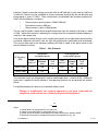
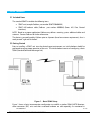
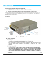
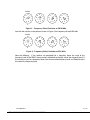
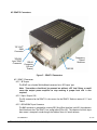
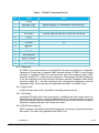
Operations Manual User’s Manual The most important thing we build is trust. The most important thing we build is trust. Standard Definition Messenger Transmitter (SDMT-C) (SDMT-S) OPERATIONS MANUAL OP1920606 Rev 1 13 Apr 2011 1 of 29 GMS Inc. doing business as Cobham Tactical Communications and Surveillance Cobham Tactical Communications and Surveillance 1916 Palomar Oaks Way, Suite 100, Carlsbad, CA 92008 Tel: 760-496-0055 FAX: 760-496-0057 www.cobham.com/tcs Table of Contents 1. Important Warning and General Safety Information .................................................................................................5 1.1 General ...........................................................................................................................................................................................................5 1.2 RF Emissions ................................................................................................................................................................................................5 2. Acronyms ....................................................................................................................................................................................................8 3. Introduction .............................................................................................................................................................................................9 3.1 About the Manual.....................................................................................................................................................................................9 3.2 Warranty .......................................................................................................................................................................................................9 3.3 Safe Operating Procedures ..................................................................................................................................................................9 4. General System Information .....................................................................................................................................................10 4.1 Overview ....................................................................................................................................................................................................10 4.2 Key System Features............................................................................................................................................................................10 4.3 Theory of Operation ............................................................................................................................................................................10 5. Initial Checkout ..................................................................................................................................................................................12 5.1 Included Items ........................................................................................................................................................................................12 5.2 Getting Started .......................................................................................................................................................................................12 6. Hardware Overview ...........................................................................................................................................................................14 6.1 : SDMT-C ....................................................................................................................................................................................................14 6.1.1 SDMT-C Connectors ...................................................................................................................................................................14 6.1.2 Frequency Select Switches ......................................................................................................................................................16 6.2 SDMT-S Connectors.............................................................................................................................................................................18 6.2.1 SDMT-S Connectors....................................................................................................................................................................18 6.2.2 Frequency Select Switches ......................................................................................................................................................19 6.3 Inline Camera Unit (Optional) .........................................................................................................................................................19 6.3.1 SDMT Inline Camera Mount Connectors .........................................................................................................................19 7. Software Overview (if not extracted to another document) ..............................................................................21 8. Specifications .......................................................................................................................................................................................22 8.1 Video Encoding ......................................................................................................................................................................................22 8.2 Audio Encoding ......................................................................................................................................................................................22 8.3 Transport Stream ...................................................................................................................................................................................22 8.4 RS-232 Interfaces/RCU/USB ............................................................................................................................................................23 8.5 COFDM RF Output.................................................................................................................................................................................23 8.6 Modulation ...............................................................................................................................................................................................23 8.7 Power ...........................................................................................................................................................................................................23 8.8 Physical Dimensions (without mating connectors)...............................................................................................................23 8.9 Environmental .........................................................................................................................................................................................24 9. D/C (Down Converter) IF frequencies explained ........................................................................................................25 9.1 IF Frequencies .........................................................................................................................................................................................25 OP1920606 Rev 1 GMS Inc. doing business as Cobham Tactical Communications and Surveillance 2 of 29 www.cobham.com/tcs 9.2 Local and Remote Power for Down Converters ......................................................................................................................25 9.2.1 Remote Power ................................................................................................................................................................................25 9.2.2 Local Power .....................................................................................................................................................................................25 10. Cable Losses ........................................................................................................................................................................................27 10.1 Coax Cable .............................................................................................................................................................................................27 List of Tables Table 1 – Safe Distances ..................................................................................................................................................................................... 6 Table 2 – I/O DB-44 Connector Pin Out................................................................................................................................................... 15 Table 3 – I/O DB-15 Connector Pin Out................................................................................................................................................... 20 Table 4 - DB-9 Connector Pin Out for the D/C...................................................................................................................................... 26 List of Figures Figure 1 – Basic SDML Setup ......................................................................................................................................................................... 12 Figure 2 – SDMT-C Connectors.................................................................................................................................................................... 14 Figure 3 – Frequency Select Switches at 2014 MHz ......................................................................................................................... 17 Figure 4 - Frequency Select Switches at 924 MHz ............................................................................................................................. 17 Figure 5 – SDMT-S Connectors .................................................................................................................................................................... 18 Figure 6 – SDMT Inline Camera Unit ......................................................................................................................................................... 19 Figure 7– BDC Connectors ............................................................................................................................................................................. 26 List of Appendices Appendix A - Bibliography ................................................................................................................................................................28 Appendix B - Cable, M2T External Breakout Cable .........................................................................................................29 OP1920606 Rev 1 GMS Inc. doing business as Cobham Tactical Communications and Surveillance 3 of 29 www.cobham.com/tcs Revision History Edited by Revision Date X2E 15 Jul 2010 Added note:- when scrambling mode is changed transmitter will reboot X3 5 Apr 2011 Added FCC warnings; extracted Status & Control Software into 100M0168X1; updated Cobham branding DRF 13 Apr 2011 Initial Release conversion of 100-M0065X3 DRF 1 Main Changes from Previous version JC OP1920606 Rev 1 GMS Inc. doing business as Cobham Tactical Communications and Surveillance 4 of 29 www.cobham.com/tcs 1. Important Warning and General Safety Information 1.1 General The following information is presented to the operator to ensure awareness of potential harmful RF (radio frequency) exposure and general hazards. With regards to potential harmful RF electromagnetic fields the text below is only a brief summary highlighting the possible risks and how to minimize exposure. The summary is based on OET Bulletin 65 “Evaluating Compliance with FCC Guidelines for Human Exposure to Radiofrequency Electromagnetic Fields” (1). The user should carefully read and comprehend the following before operating the equipment and for additional in depth information refer to OET Bulletin 65. 1.2 RF Emissions The FCC has set guidelines (Cleveland, Jr., Sylvar, & Ulcek, 1997) for evaluating exposure to RF emissions that the user must be aware of when operating Cobham’s’ SDMT microwave transmitter. The maximum power density allowed at 1500-7000 MHZ is 5mW/cm2 for occupational/controlled exposure1 and 1mW/cm2 for general population/uncontrolled exposure2. These are the limits for maximum permissible exposure (MPE) as called out in the FCC guidelines (for the above mentioned frequencies). 1 “Occupational /controlled exposure limits apply to situations in which persons are exposed as a consequence of their employment and in which those persons who are exposed have been made fully aware of the potential for exposure and can exercise control over their exposure. Occupational/controlled exposure limits also apply where exposure is of a transient nature as a result of incidental passage through a location where exposure levels may be above general population/uncontrolled limits (see below), as long as the exposed person has been made fully aware of the potential for exposure and can exercise control over his or her exposure by leaving the area or by some other appropriate means. …….” 2 “General population/uncontrolled exposure limits apply to situations in which the general public may be exposed or in which persons who are exposed as a consequence of their employment may not be made fully aware of the potential for exposure or cannot exercise control over their exposure. Therefore, members of the general public would always be considered under this category when exposure is not employment-related, for example, in the case of a telecommunications tower that exposes persons in a nearby residential area.” OP1920606 Rev 1 GMS Inc. doing business as Cobham Tactical Communications and Surveillance 5 of 29 www.cobham.com/tcs Exposure is based on upon the average time spent within the RF field with a given intensity (field units in mW/cm2). Hence it may be controlled (or at least minimized) by observing the safe distances and time exposed as shown in Table 1. These safe distances are calculated from equations predicting RF Fields3 with the following assumptions: • The transmitter maximum power is 23dBm (200 mW) • The antenna used has a 2dBi gain • The transmitter is used in a fixed location The user (and bystanders) should remain beyond the distances from the antenna at all times as stated in Table 1 when the transmitter is operating for no longer than the time periods indicated (keeping in mind this is the average time). If any of the above variables change, such as a higher gain antenna, less or more power output from the transmitter, additional transmitters used, etc. then the safe distances would need to be recalculated. The user can either refer to the equations predicting RF Fields as noted in the above section or call contact Cobham for advice. Table 1 – Safe Distances RF Frequency (MHz) Occupational controlled exposure Limit (mW/cm2) Safe Distance (cm) 1000 to 1500 3.3 2.8 1500 to 7000 5 2.2 General population uncontrolled exposure Average Time (min) 6 SDMT Transmitter Power = 0.2W (+23 dBm) Limit (mW/cm2) Safe Distance (cm) 0.67 6.2 1 5 Average Time (Min) 30 Antenna Gain = +2dbi The transmitter, which can be operated in fixed or mobile applications, is rated at 0.2W (+23dBm) RF power and is capable of harmful radiation if safe operating practices are not observed (see sections above). It should be noted that this device is an intentional radiator, hence: Changes or modifications not expressly approved by the party responsible for compliance could void the user’s authority to operate the equipment. 3 4 where: S = power density (in appropriate units, e.g. mW/cm2) P = power input to the antenna (in appropriate units, e.g., mW) G = power gain of the antenna in the direction of interest relative to an isotropic radiator R = distance to the center of radiation of the antenna (appropriate units, e.g., cm) OP1920606 Rev 1 GMS Inc. doing business as Cobham Tactical Communications and Surveillance 6 of 29 www.cobham.com/tcs NOTE: The manufacturer is not responsible for any radio or TV interference caused by unauthorized modifications to this equipment. Such modifications could void the user’s authority to operate the equipment. Do not substitute any antenna for the one supplied or recommended by the manufacturer. The installer is responsible for ensuring that the proper antenna is installed. Antenna minimum safe operating distances should be observed as stated in section 2 above. It is the responsibility of the qualified end-user of this intentional radiator to control the safe distances and exposure limits to bystanders. DC power (+12VDC) to the unit should never be applied until the antenna (or other suitable load) has been attached to the device SMA RF output connector. Safe operating procedures must be observed when unit is transmitting into an antenna (see sections above). OP1920606 Rev 1 GMS Inc. doing business as Cobham Tactical Communications and Surveillance 7 of 29 www.cobham.com/tcs 2. Acronyms This section lists and describes the various acronyms used in this document. Name Meaning 16 QAM 64 QAM A/V AES ASI BDC or BDCC COFDM CVBS/Y C D/C FEC GUI HD I/O Kbaud Kbps Mbps MER MPEG MSR M2D M2T M2L NTSC PAL QPSK RF RX S/N THD SD SDI TX VDC 16-state Quadrature Amplitude Modulation 64-state Quadrature Amplitude Modulation Audio/Video Advanced Encryption System (32 bit) Asynchronous Serial Interface Block down converter Coded Orthogonal Frequency Division Multiplexing Composite video/Luminance with S-video Chroma video Down-Converter Forward Error Correction Graphical User Interface High Definition Input/ Output Kilobaud per second Kilobits per second Megabits per second Modulation Error Rate Moving Picture Experts Group Messenger Smart Receiver Messenger Two Decoder Messenger Two Transmitter Messenger Two Link National Television System Committee Phase Alternation Line Quadrature Phase Shift Keying Radio Frequency Receiver Signal-to-Noise Ratio Total Harmonic Distortion Standard Definition Serial Digital Interface Transmitter Volts (Direct Current) OP1920606 Rev 1 GMS Inc. doing business as Cobham Tactical Communications and Surveillance 8 of 29 www.cobham.com/tcs 3. Introduction 3.1 About the Manual Cobham User Manuals focus on providing the end user an easy to understand operational instructions to quickly setup and deploy the equipment. The Cobham Technical Operation Manuals focus on the technical details and setup of the equipment. The Technical Manuals also provide a more in depth explanation of the settings and specifications of the equipment that technicians can use to verify the operational status. 3.2 Warranty Cobham offers a 12 month standard product warranty. During this period, should the customer encounter a fault with the equipment we recommend the following course of action: Check the support section of the website for information on that product and any software/firmware upgrades. If fault persists call our support line and report the fault. If fault persists and you are informed to return the product, please obtain an RMA number from the Cobham support department or website and ship the equipment with the RMA number displayed and a description of the fault. Please email the support section the airway bill/consignment number for tracking purposes. Depending on the nature of the fault, Cobham endeavor to repair the equipment and return it to the customer within 14 days of the item arriving at our workshops. Obviously it is impossible to cater for all types of faults and to manage 100% replacement part availability, and delays are sometimes inevitable. Please contact Cobham for details of packages that can be tailored to meet your individual needs, whether they are service availability, technical training, local geographic support or dedicated spares holdings. 3.3 Safe Operating Procedures Ensure that the power supply arrangements are adequate to meet the requirements of VETA product. Operate within the environmental limits specified for the product. The transmitter will generate considerable heat and it is the responsibility of the end user to properly heat sink the device before using. Electro-Static Discharge (ESD) precautions should be observed as a safe practice. Only authorized, trained personnel should open the product. There are no functions that required the User to gain access to the interior of the product. OP1920606 Rev 1 GMS Inc. doing business as Cobham Tactical Communications and Surveillance 9 of 29 www.cobham.com/tcs 4. General System Information 4.1 Overview Cobham’s Standard Definition Messenger Transmitter (SDMT-C) is one of the smallest and lowest power consumption DVD-T (Digital Video Broadcasting-Terrestrial) compliant COFDM (Coded Orthogonal Frequency Division Multiplexed) transmitter available. There are three SDMT models; the SDMT-C supports standard analog video and audio signals, the SDMT-S which adds an SDI interface, and the SDMT-A. The SMDT-A supports ASI Transport Stream inputs only. Note that the MPEG Encoder is removed on this model. These transmitters may be supplied as standalone products or may be configured in an optional Camera Box that is compatible with most professional cameras. Additionally, Cobham offers a wide variety of companion products required to form a complete link. A Standard Definition Messenger Link (SDML) is formed when one of the SDMT models is combined with one of Cobham’s Messenger Digital Receivers, one or two external Down-Converters, antennas, and a SD MPEG-2 decoder. The SDML uses a robust digital modulation system known as Coded Orthogonal Frequency Division Multiplexed (COFDM) that provides frequency diversity and powerful Forward Error Correction (FEC) algorithms. The SDML provides a robust wireless link that is effective against the multi-path interference experienced by analog systems, and provides crisp, clear pictures in the most difficult of terrains. Additionally, the SDMT/DDR (Standard Definition Messenger Transmitter and Digital Diversity Receiver) combination in SP@ML mode can provide an end-to-end latency down to approx. 198ms without the introduction of any further MPEG encoding artifacts. This ensures that the picture you see is what is happening now – crucial for applications such as sports coverage, surveillance, and law enforcement, where personnel are reacting to real-time events. This manual provides information on how to operate each of the SDMT models as well as pertinent technical information related to the overall system. Also, refer to model identifier (on-line document), at Cobham’s website, http://www.cobham.com/tcs, for available frequency and power configurations along with available options. 4.2 Key System Features Component, S-Video & Composite with Optional SDI/ASI or ASI Only Interfaces Built in 4:2:0 MPEG-2 Video Encoder and MPEG-1 Layer II Audio Encoder Coded Orthogonal Frequency Division Multiplexed (COFDM) Modulation Output Frequency 0.36 to 6 GHz (In-Bands) Low Power Consumption Local and Remote Control Interfaces Rugged and Compact Portable Design 4.3 Theory of Operation The SDMT accepts Composite, S-Video, Component video, SDI/ASI (optional) as well as up to two audio channels (Microphone or line level). The video and audio are compressed (ASI data streams are passed through bypassing the MPEG encoder) according to MPEG specifications (Video MPEG-2 and Audio MPEG1 layer II). The MPEG-2 supports 4:2:0 Chroma sampling, MP@ML and SP@ML profiles and maintains the OP1920606 Rev 1 GMS Inc. doing business as Cobham Tactical Communications and Surveillance 10 of 29 www.cobham.com/tcs original signal’s video fidelity. The audio and video program element streams are multiplexed with basic service data to indicate the service name into a DVB compliant Transport Stream (TS). The TS stream is then sent through a DVB-T compliant FEC encoder and COFDM modulator. This is output from the FPGA based modulator core as digital I/Q signals that are converted to Analog I/Q signals and applied to an I/Q Modulator. The LO that provides the carrier to this I/Q modulator comes from a low phase-noise programmable synthesizer. The modulated RF output of the I/Q modulator IC is sent through amplifier chain and ultimately output to the outside world. Programmable attenuators in the RF processing chain provide signal leveling. The transmitter is microprocessor controlled. Normally the transmitter is controlled either through an RS232 or USB interface via either GMS’ MS Windows control SW or a simple command line interface. Local Frequency control is also available via rotary switches on the side of the housing. OP1920606 Rev 1 GMS Inc. doing business as Cobham Tactical Communications and Surveillance 11 of 29 www.cobham.com/tcs 5. Initial Checkout 5.1 Included Items The standard SDMT kit includes the following items: SDMT unit (example Cobham part number SDMTCCBA0NXXX) SDMT full breakout cable (Cobham interfaces) part number 4009004) (Power, A/V, Data, Control NOTE: Based on customer application Cobham may deliver a receiving system, additional cables and antennas. Contact Cobham for further information. The device is pre-configured by Cobham prior to shipment (based on customer requirements), thus is ready to work “right out of the box”. 5.2 Getting Started Prior to installing a SDMT unit into the desired target environment, an initial checkout should be performed to ensure proper operation of the unit. The initial checkout consists of configuring a basic SDML (Standard Definition Messenger Link). Figure 1 – Basic SDML Setup Figure 1 shows a basic interconnection configuration to establish a wireless SDML (NOTE: Receivers, down converters (D/C) units and their associated hardware are sold separately). As mentioned in OP1920606 Rev 1 GMS Inc. doing business as Cobham Tactical Communications and Surveillance 12 of 29 www.cobham.com/tcs section 6 the SDMT may be shipped as a stand-alone unit or mounted in an Inline Camera Mount box. SDMT stand-alone units require the use of Cobham’s breakout cable to provide power and the necessary interfacing to communicate to the transmitter. The Inline Camera Mount boxes require a +12 battery and most of the necessary communications can be done through the LCD front panel. The steps necessary to set up the configuration shown in Figure 1 are shown below; the differences between the Inline Camera Mount box and stand-alone unit are noted where applicable. OP1920606 Rev 1 GMS Inc. doing business as Cobham Tactical Communications and Surveillance 13 of 29 www.cobham.com/tcs 6. Hardware Overview There are two basic transmitter configurations for the SDMT: The SDMT-C which accepts Composite, S-Video and Component Video, The SDMT-S which accepts Composite, S-Video, Component Video, SDI and ASI inputs In addition all two configurations of the SDMT can be mounted in an inline professional camera unit (this is an optional enclosure for mounting the SDMT for professional camera applications). The hardware for each configuration is shown below: 6.1 : SDMT-C “RF-OUT” SMA Connector DB-44 Connector (I/O and Power) Frequency Select Switches SW100 Figure 2 – SDMT-C Connectors 6.1.1 SDMT-C Connectors 6.1.1.1 RF Output The SDMT uses a female SMA bulkhead connector for its ‘RF Output’ port. Note: Transmitters should not be powered on without a RF load. Doing so could cause the output power amplifier to stop working. A proper heat sink is also required. 6.1.1.2 Input / Output (I/O) The I/O connector is a male, high-density DB-44. It provides the interface for external power, audio, analog video, USB, and RS-232 signals. The SDMT has a separate RS232 channel (labeled “Control” on the external breakout cable) for control and monitoring the unit. Cobham’s SDMT Status & Control software program (as explained in section 6.3.1.3) makes use of the RS232 OP1920606 Rev 1 GMS Inc. doing business as Cobham Tactical Communications and Surveillance 14 of 29 www.cobham.com/tcs control lines. The RS-232 channel utilizes a 3-wire configuration. The pin out for the I/O connector is shown in Table 2 NOTE: An additional RS232 channel (labeled “USER DATA”) is currently provided with the external breakout cable. The “USER Data” RS232 channel is dedicated for low-rate data to be transmitted along with the audio and video. The USB connector is an alternate method of interfacing to the PC if DB-9 connectors are not available.. Table 2 – I/O DB-44 Connector Pin Out Pin Signal Notes 1 RS232 Data Tx 2 RS232 Data Rx 3 RS232 GND 4 Not connected 5 SDA I^2 C bus 6 SCL I^2 C bus 7 CVBS/Y Dual use input. 1. Composite video in; 2. Luminance in (when used with S or Component Video). Must be selected with Cobham’s Status & Control Software or through the front panel of the in-line camera mount box 8 GND GND for composite video 9 C/Pr Dual use input. 1. Chroma video (when used with S-video); 2. Pr (red component when used with Component Video). Must be selected with Cobham’s Status & Control Software or through the front panel of the in-line camera mount box. 10 GND GND for Chroma video/Pr component 11 Pb Blue component when used with Component Video. 12 GND GND for Pb component 13 GND GND 14 11-15Vdc Input power to unit 15 Not connected OP1920606 Rev 1 GMS Inc. doing business as Cobham Tactical Communications and Surveillance 15 of 29 www.cobham.com/tcs Pin Signal Notes 16 USB power, Reset +5V 17 USB Data - 18 USB Data + 19 USB GND 20-29 Not connected 30 PA Shut Down 31 RS232 Control Tx 32 RS232 Control-Rx 33 34-36 RS232 GND Not connected 37 38 Audio right + Audio right - 39 Audio right line opt. 40 41 42 Audio right GND Audio left + Audio left - 43 Audio left line opt 44 Audio left GND Provides a TTL signal [+3V} to enable an external PA. Pin 39 is connected to pin 38 for audio right channel input impedance of 600 ohms, balance in (microphone or line level) Pin 43 is connected to pin 42 for audio left channel input impedance of 600 ohms; balance in (microphone or line level). 6.1.2 Frequency Select Switches There are four external rotary switches mounted into the chassis of the SDMT (see Figure 2 & Figure 5). They are used to control RF frequency selection manually. Frequency selection can also be controlled through Cobham status & control software; see section 6.3.1.3. The rotary switches can be disabled or enabled using Cobham status & control software. The most significant switch (SW100) represents 1000 MHz (0-9) units, the second switch (SW101) represents 100 MHz (0-9) units, the third switch (SW102) represents 10 MHz (0-9) units and the fourth switch (SW103) represents 1 MHz (0-9) units. Therefore, the highest switch selection is 9999 MHz and the lowest is 0000 MHz. For example with the switches in the positions shown in Figure 3, the frequency will read 2014 MHz: OP1920606 Rev 1 GMS Inc. doing business as Cobham Tactical Communications and Surveillance 16 of 29 www.cobham.com/tcs SW100 9 0 1 8 7 6 5 2 3 4 9 0 1 8 7 6 5 0 2 2 3 4 9 0 1 8 7 6 5 1 2 3 4 9 0 1 8 7 6 5 4 2 3 4 Figure 3 – Frequency Select Switches at 2014 MHz And with the switches in the positions shown in Figure 4, the frequency will read 924 MHz. SW100 9 0 1 8 7 6 5 0 2 3 4 9 0 1 8 7 6 5 9 2 3 4 9 0 1 8 7 6 5 2 2 3 4 9 0 1 8 7 6 5 4 2 3 4 Figure 4 - Frequency Select Switches at 924 MHz Note the following: if the switches are positioned for a frequency above the range of the frequency band of the SDMT; the transmitter will default to the high side of the frequency band. If the switches are set for a frequency lower than the transmitter frequency band, it will default to the low side of the frequency band. OP1920606 Rev 1 GMS Inc. doing business as Cobham Tactical Communications and Surveillance 17 of 29 www.cobham.com/tcs 6.2 SDMT-S Connectors “RF-OUT” SMA Connector “SDI/ASI Input” BNC Connector Frequency Select Switches DB-44 Connector (I/O and Power) SW100 Figure 5 – SDMT-S Connectors 6.2.1 SDMT-S Connectors 6.2.1.1 RF Ouptut The SDMT uses a female SMA bulkhead connector for its ‘RF Output’ port. Note: Transmitters should not be powered on without a RF load. Doing so could cause the output power amplifier to stop working. A proper heat sink is also required. 6.2.1.2 Input / Output (I/O) The I/O connector for the SDMT-S is the same as for the SDMT-C. Refer to section 6.1.1.2 and Table 2. 6.2.1.3 SDI/ASI BNC Input Connector The BNC connector is provided for inserting SDI (Serial Data Interface) and ASI (Asynchronous Serial Interface) data. The SDMT-S can accept either SDI or ASI. The selection for which input data stream is accepted is made through the Cobham Status & Control software. OP1920606 Rev 1 GMS Inc. doing business as Cobham Tactical Communications and Surveillance 18 of 29 www.cobham.com/tcs 6.2.2 Frequency Select Switches The frequency select switches are the same as the SDMT-C. See section 6.1.2 above for the operational description. 6.3 Inline Camera Unit (Optional) Figure 6 – SDMT Inline Camera Unit 6.3.1 SDMT Inline Camera Mount Connectors There are four BNC connectors, two audio XLR, one DB-15 connector, one N type connector and one rocker on/off power switch located on the SDMT inline camera unit for interfacing the RF, audio, video, power and RS-232 signals. An optional LCD control front panel is also available. Inline camera mount is shown in Figure 6. 6.3.1.1 RF Output The SDMT in line camera enclosure uses a female N type connector (flange mount) for its ‘RF Output’ port. Note: Transmitters should not be powered on without a RF load. Doing so could cause the output power amplifier to stop working. A proper heat sink is also required. 6.3.1.2 Input / Output (I/O) The ‘I/O’ connector is a female, DB-15. It is used to provide the interface for RS-232 signals (control and monitoring). Cobham’s SDMT Status & Control software program makes use of the RS232 control lines, pins 2, 3 and 5 of the DB-15 connector. The RS-232 channel utilizes a 3wire configuration. The pin out for I/O connector is shown in Table 3. A USB connection is also provided if RS232 port is not available. OP1920606 Rev 1 GMS Inc. doing business as Cobham Tactical Communications and Surveillance 19 of 29 www.cobham.com/tcs Table 3 – I/O DB-15 Connector Pin Out Pin Signal 1 2 3 4 5 6 7 8 9 10 11 12 13 14 15 +12Vdc RS232-Rx (CTRL) RS232-Tx (CTRL) Not connected RS232-GND I^2C_D I^2C_C USB Reset USB Data USB Data + USB GND Not connected RS232-Tx (DATA) RS232-Rx (DATA) RS232-GND Notes Relative to SDMT (i.e., control data is input on this pin) Relative to SDMT (i.e., control data is output on this pin) Common ground for both RS232 Data and Control lines +5V 6.3.1.3 Video Input The SDMT in-line camera enclosure uses female BNC connectors for video input. Component, Composite or S-Video input is accepted. J3 BNC connector marked “Y/COMP” is a dual use input connector; a) Composite Video or b) Luminance when used with Component video. J2 BNC connector marked “C/Pr” is a dual use input connector; a) Chroma when used with S-Video or b) Pr, the red component minus the luminance information used with Component Video. J8 BNC connector marked “Pb” is the blue component minus the luminance information used with Component Video. These video inputs are applicable to the SDMT-C and SDMT-S units. 6.3.1.4 Power Switch An LED indicator rocker switch is provided for controlling power to the unit. 6.3.1.5 LCD Display An optional LCD display with a front control panel is available for the inline camera mount unit. Many of the control functions normally handled through the PC software interface can now be accessed directly with the front control panel. The LCD can perform such functions as changing frequencies, checking video lock status among many others. 6.3.1.6 SDI/ASI Input (optional) A BNC connector is provided for Serial Digital Interface or Asynchronous Digital Interface input data streams. This input is only applicable to the SDMT-S unit. OP1920606 Rev 1 GMS Inc. doing business as Cobham Tactical Communications and Surveillance 20 of 29 www.cobham.com/tcs 7. Software Overview (if not extracted to another document) Configuration, control and monitoring of the SDMT units are done by using Cobham’s’ MS Windowsbased SDMT Status & Control software program (8970908). This Graphical User Interface (GUI) program provides the end user with a straightforward way to interface with the SDMT unit. During normal operation, once a link is established, the SDMT GUI does not need to be active and can be disconnected from the SDMT unit. Refer to the Software Manual for further information. OP1920606 Rev 1 GMS Inc. doing business as Cobham Tactical Communications and Surveillance 21 of 29 www.cobham.com/tcs 8. Specifications The following sections outline the overall specifications for the SDMT unit. 8.1 Video Encoding Interfaces: SDI (optional), Component, Composite or S-Video Input Standards: NTSC or PAL Compression Standard: MPEG-2 (per ISO/IEC 13818-2) Profiles: MP@ML, SP@ML Video Bit Rate: 3.7 Mbps to 15 Mbps (MP@ML) Chrominance Profile: 4:2:0 Line Standard: 525 or 625 Horizontal Resolution: 704 pixels Vertical Resolution: 576 (625 line) and 480 (525 line) System Latency end to end delay: 198 mS with SDMT/DDR combination in SP@ML mode. 8.2 Audio Encoding Analog Audio: Dual, Line-Level or Mic-Level, Differential or Single-Ended, Clip Level 12 dBm Impedance: 600 Ohms input impedance (changeable to 2K Ohms) Compression Standard: MPEG layer II Audio Enable: On or Off Bit Rates: 256 Kbit/s/ch Sampling Frequency: 32 kHz, 44.1 kHz or 48 kHz THD: < 0.1% maximum Response: 20 Hz to 12 kHz, +/- 0.25dB Crosstalk: >55 dB minimum S/N: >60 dB RMS 8.3 Transport Stream Standard: per ISO/IEC 13818-1 Packet Size: 188 byte Bit Rate: Automatically set from active service settings. ASI Input (optional): Allows MPEG2 transport stream to be inserted into the SDMT-A and SDMT-S units through the BNC connector OP1920606 Rev 1 GMS Inc. doing business as Cobham Tactical Communications and Surveillance 22 of 29 www.cobham.com/tcs 8.4 RS-232 Interfaces/RCU/USB Control Port: 3-wire interface (Tx,Rx,Gnd) USB 1.0 RCU A remote portable control unit is also available In addition a “Data” RS232 channel is available dedicated for low-rate data to be transmitted along with the audio and video. 8.5 COFDM RF Output Output Frequency: 0.36 to 6 GHz (In-Bands). Frequency step size is 500 KHz for all bands except S2 (1999-2500MHz) which is 250 KHz. Bandwidth: Selectable 6, 7 or 8 MHz Output Power: Up to100mW (programmable) [200mW on some models] Connector: SMA-F Note: Transmitters should not be powered on without a load. Doing so could cause the output PA to stop working. A proper heat sink is also required. 8.6 Modulation Modulation Type: COFDM w/ QPSK, 16 QAM (64 QAM available with SDMT-S and SDMT-A units when ASI input is selected). FEC: ½, 2/3, ¾, 7/8 (not all available, SDMT configuration type dependent) Guard Intervals: 1/32, 1/16, 1/8, ¼ (not all available, SDMT configuration type dependent) Spurious: 50dBc Number of COFDM Carriers: 2k COFDM MER: > -45dB Standard: DVB-T compliant 8.7 Power DC Input Voltage Range: 9 to 15 VDC Power Consumption: 8.5 Watts to 10.8watts (SDMT configuration type dependent) 8.8 Physical Dimensions (without mating connectors) SDMT-C unit Size: 3.25 in. (W) x 4.5 in. (D) x 1.00 in. (H) (8.26 cm x 11.43cm x 2.54cm) Weight: 10.69 oz. (303.1 grams) OP1920606 Rev 1 GMS Inc. doing business as Cobham Tactical Communications and Surveillance 23 of 29 www.cobham.com/tcs SDMT-S/A units Size: 3.25 in. (W) x 4.5 in. (D) x 1.76 in. (H) (8.26 cm x 11.43cm x 4.47cm) Weight: 13.4 oz. (379.9grams) 8.9 Environmental Operational Temperature: -10 to +70 C Humidity: Up to 100% (non-condensing) OP1920606 Rev 1 GMS Inc. doing business as Cobham Tactical Communications and Surveillance 24 of 29 www.cobham.com/tcs 9. D/C (Down Converter) IF frequencies explained 9.1 IF Frequencies MSR receivers (and many other digital receivers) are capable of receiving direct frequencies in the range of approximately 49 MHz to 861 MHz. If the transmitter is not in this range then a downconverter (also refer to a BDC, block down converter) is used to convert the frequency to this range. The frequency out of the down-converter is called the IF (intermediate frequency) which is fed to the receiver. Down-converters have a LO (local oscillator) which is mixed with the transmitter frequency (M2T) and converts it to the IF frequency. MSR receivers need to know the LO (local oscillator) of the downconverter and the RF frequency of the transmitter. It then automatically calculates the IF frequency. The IF frequency changes as the RF frequency changes. However, the LO remains constant. On non-GMS receivers it may be necessary to program the receiver with the IF frequency directly. The user may have to do the simple math to arrive at the IF frequency so that it can be entered into the receiver. The down-converter LO must be known. The math involve is as follows: “LO – transmitter frequency (or transmitter frequency – LO) = IF frequency”. For example, it the transmitter is set for 2000 MHz and the LO of the down-converter is 2800 MHz then the IF frequency is 800 MHz (28002000 = 800). The receiver will need to be set to 800 MHz to receive the transmitter frequency of 2000 MHz. Each time the transmitter frequency is changed the IF must be re-calculated and entered into the receiver. It must also be mentioned, as you may have noticed with the equation “LO-transmitter frequency or transmitter frequency – LO” that two answers are possible. For example 2800-2000 = 800 or 2000-2800 = -800. The negative answer may indicate the receiver wants the signal to be inverted. 9.2 Local and Remote Power for Down Converters Customers have the option of using remote or local power. 9.2.1 Remote Power Remote power is provided from the MSR through the BNC connector from each of the tuners located on the rear panel. Power is turned on through the software control application (refer to the MSR online manual). The +12Vdc provided from the receiver will travel through the coax cable to the D/C. If the D/C is located relatively close to the receiver then using remote power makes sense. However, if the D/C is located at great distances away from the receiver there may be excessive DC voltage drop in the coax cable (due to cable resistances). If this is the case then local DC power should be considered as discussed below. If unsure of the DC voltage drop measure the DC voltage present (using a DMM) at the end of the coax cable run; the D/C normal operating voltage is approximately +12Vdc but can operate down to +10Vdc. 9.2.2 Local Power Local power is provided by applying +12Vdc to pin 1, GND to pin 3 of the DB-9 connector located on the bottom of the D/C. The +12 Volt power supply must be able to source at least 500mA. The power switch (located on the side of the D/C) enables the user to control the ‘ON’/’OFF’ positions for local power. If using local power then the remote power should be set to “OFF”. OP1920606 Rev 1 GMS Inc. doing business as Cobham Tactical Communications and Surveillance 25 of 29 www.cobham.com/tcs Figure 7– BDC Connectors Table 4 - DB-9 Connector Pin Out for the D/C Pin 1 3 2, 4-9 Signal Notes Power supply must be able to source at least +12Vdc 500mA. Voltage should not drop below +10Vdc. Power ground GND Not Connected NC OP1920606 Rev 1 GMS Inc. doing business as Cobham Tactical Communications and Surveillance 26 of 29 www.cobham.com/tcs 10. Cable Losses 10.1 Coax Cable Cable losses must be taken into consideration if the D/C is located a great distance from the receiver. As mentioned above long cable runs can contribute to more resistance in the lines and also can contribute to signal attenuation because of the additional capacitance. Even when using a good coax cable such as RG59/U the attenuation of the signal can be significant. For example, RG59/U coax will drop approximately 2 dB per 100 feet at 50 MHz and 8 dB per 100 feet at 900 MHz. The intermediate frequency (IF) in this system can fall between 49 MHz to 850 MHz. An inline amplifier matching the cable losses should be considered if losses exceed 6 dB. OP1920606 Rev 1 GMS Inc. doing business as Cobham Tactical Communications and Surveillance 27 of 29 www.cobham.com/tcs Appendix A - Bibliography Cleveland, Jr., R. F., Sylvar, D. M., & Ulcek, J. L. (1997, August). OET Bulletin 65Evaluating Compliance with FCC Guidelines for Human Exposure to Radiofrequency Electromagnetic Fields. Retrieved March 30, 2010, from Federal Communications Commission: http://www.fcc.gov/Bureaus/Engineering_Technology/Documents/bulletins/oet65/oet65.pdf OP1920606 Rev 1 GMS Inc. doing business as Cobham Tactical Communications and Surveillance 28 of 29 www.cobham.com/tcs Appendix B - Cable, SDMT External Breakout Cable OP1920606 Rev 1 GMS Inc. doing business as Cobham Tactical Communications and Surveillance 29 of 29 www.cobham.com/tcs