1
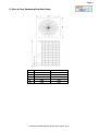
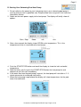
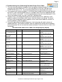
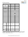
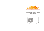
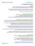
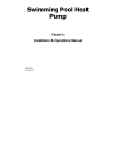
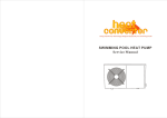
Page 1
SWIMMING POOL HEAT PUMP
Owners Manual
This manual refers to the 17.0kw and 21.0kw models only.
The heat pump unit is sold with a 1 year warranty.
In addition there is a 2 year parts warranty on the compressor
and a 5 year parts warranty on the titanium heat exchanger.
Please contact your supplying dealer in the event of a claim.
This heat pump is designed for domestic use between May and September.
To achieve satisfactory performance a minimum ambient air temperature of 15°C is required.
The heat pump needs to be run for a minimum of 8 hours in 24 during the warmest part of each day.
A solar or heat retention swimming pool cover must be used.
HeatSeeker Swimming Pool Heat Pump: Page 1 of 10
Page 2
CONTENTS
A.
Positioning
B.
Connecting Pipe Work
C.
Sizes
D.
Starting the Heat Pump
E.
Setting the Temperature
F.
Checking the Status
G. Changing the Mode
H.
Auxiliary Mode
I.
Winterising and Maintenance
J.
Troubleshooting: Error Codes
K.
Troubleshooting: Parameter Settings
L.
Accessories
M. Technical Information
HeatSeeker Swimming Pool Heat Pump: Page 2 of 10
Page 3
A. Positioning Your Swimming Pool Heat Pump
1. For correct operation air must be free to circulate around the heat pump. Do not place
the unit in a shed, greenhouse or similar. This unit is designed to be placed outdoors
only.
2. Ensure there is at least 1000mm (1.0m) of clearance all around each side of the heat
pump to allow air circulation and access for maintenance.
3. Do not block the top air exit where the fan expels air upwards from the unit. There must
be no obstruction above this air exit for at least 2000mm (2.0m).
4. You should position the heat pump so that the control panel does not face directly
towards the sun.
5. The heat pump must be upright.
6. The distance between the heat pump and the pool / plant room should be as short as
practically possible to reduce pressure and heat loss in the pipe work.
7. Insulating the pipe work will assist with the prevention of heat losses.
8. An isolator switch should be installed (by a qualified electrician) near the heat pump.
9. The electrical supply to the heat pump must be protected by a 30mA RCD.
10. The air inlets and outlets must not be obstructed or blocked.
11. Even though the heat pump is low noise, it must be positioned so as to be considerate
to neighbours.
12. Your heat pump must be placed on a solid base.
13. Condensation will drip from underneath the heat pump, your base must be able to
tolerate this.
B. Connecting Your Swimming Pool Pipe Work
1. The pool water is fed through the heat pump by a swimming pool pump.
2. The heat pump must be installed after (down stream) the swimming pool filter so clean,
filtered water passes through it.
3. Double union ball valves must be fitted just before the heat pump inlet and just after the
outlet to aid servicing and winterising.
4. Each heat pump has a maximum water flow rate. If the flow via the pool pump is higher
than this then a by-pass should be installed. Consult your supplying dealer.
5. Each heat pump also has a minimum flow rate, below this the heat pump will not
operate. Consult your supplying dealer.
6. Pipe work of less than 1½" diameter should not be used.
7. Fit a union nut onto each pipe.
8. Push the gasket over the pipe until the gasket is about 5 -10mm from the edge of the
pipe. You may need to lubricate the gasket.
9. Insert the pipe into the heat pump and tighten the union nut.
10. The union must only be hand tightened.
11. If the swimming pool is equipped with a chlorinator, brominator, or possibly chemical
control with acid and chlorine pumps, these must be in the return pipe work after the
heat pump and a non-return valve used. Any dosing system must be the final
equipment before the water returns to the swimming pool. Damage caused to the heat
pump by chemical dosing units is not covered by warranty.
12. Any heat exchanger or electric heater fitted as auxiliary heating must be installed after
(down stream from) the heat pump so as to avoid pre-heating the pool water before it
enters the heat pump.
HeatSeeker Swimming Pool Heat Pump: Page 3 of 10
Page 4
C. Sizes of Your Swimming Pool Heat Pump
A
B
C
F
G
WBR-17.0H-A
855
660
660
370
110
WBR-21.0H-A-S
955
660
660
370
110
HeatSeeker Swimming Pool Heat Pump: Page 4 of 10
Page 5
D. Starting Your Swimming Pool Heat Pump
1. Do not switch on the power to your heat pump unless your swimming pool pump is
running and you have a good flow rate. Required flow rates are given in the technical
information section.
2. Switch on the main power supply to the heat pump. The display will briefly show all
options.
Start / Stop
Mode
Set
Aux
3. After a few seconds the display shows ROOM and a temperature. This is the
temperature of the air surrounding the heat pump.
4. Push the START/STOP button and await the display to show the inlet and outlet
temperature.
5. Note that when you first push the START/STOP button the heat pump fan and
compressor will not start immediately.
6. If the water flow from the pool pump is correct, the heat pump will start after a 2 - 3
minute pause due to a delayed start facility.
7. When the heat pump is operational the display will show temperatures for the pool
water inlet and outlet.
HeatSeeker Swimming Pool Heat Pump: Page 5 of 10
Page 6
E. Setting the Temperature of Your Swimming Pool Heat Pump
1. If your heat pump fan and compressor is running press the START/STOP button to
make the heat pump enter its standby mode.
2. Press the set button repeatedly until SET NO 01 shows with the set point temperature
in degrees C.
3. Use the up arrow button and the down arrow button to adjust the set point temperature
to your desired point. If you have a liner type swimming pool do not exceed the
recommended maximum temperature for the liner (often 28°C).
4. The display will return to the standby mode after a few seconds.
5. Restart the heat pump by pressing the START/STOP button.
6. After the 2 – 3 minute delay the heat pump will re-start with the new set temperature.
F. Checking the Status of Your Swimming Pool Heat Pump
1. When the heat pump is running press the up or down arrow to scroll through the status
readings as below.
2. IN & OUT are the respective temperatures at the water inlet and outlet. Note that when
you have a good flow rate through the heat pump the difference may be less than 1°C
so it appears there is no difference.
3. P1 is the temperature of condenser 1, P2 is the temperature of condenser 2. Note that
some models have just one condenser so a reading may not be present for both P1 &
P2.
4. ROOM is the temperature of the air around the heat pump.
HeatSeeker Swimming Pool Heat Pump: Page 6 of 10
Page 7
G. Changing the Mode of Your Swimming Pool Heat Pump
1. In some regions the swimming pool heat pump is equipped with the option to cool the
swimming down.
2. Make sure the heat pump is in standby (power on but fan and compressor not running)
by using the START/STOP button.
3. Press the MODE button to scroll through the available modes.
4. The snow flake symbol indicates cooling.
5. The sunshine symbol indicates heating.
6. The three arrows in a triangle is the automatic mode where the heat pump would
choose to heat or cool the pool depending on the set temperature.
7. For pool heating in the UK keep the heat pump in the heating mode (sunshine symbol).
8. If pressing the MODE button does not change the mode and the heat pump remains in
the heat mode (sunshine symbol) then the cooling and automatic modes have been
deactivated.
9. If pressing the MODE button does not change the mode and the heat pump is not in
the heating mode, firstly make sure you are in standby and then try again. If you can
not change the mode at all refer to the troubleshooting (changing parameters) section.
H. Auxiliary Mode of Your Swimming Pool Heat Pump
1. The AUX button on the heat pump is not used.
2. When pressed the AUX button may make a wavy line symbol appear and disappear on
the display but no equipment is operated.
I. Winterising and Maintenance of Your Swimming Pool Heat Pump
1. At all times only let swimming pool water through the heat pump which has the correct
chemical balance.
• Chlorine not to exceed 3 ppm
• pH between 7.2 and 7.7
• Total Alkalinity 90 – 150 ppm
• Calcium Hardness 100 – 400 ppm
2. When it is decided to close down the swimming pool for the winter it is important that
the heat pump be immediately emptied of water.
3. Ensure that pool water can not freely flow out of the pool and then loosen both coupling
nuts to the pipe work and withdraw the pipes from the heat pump.
4. Drain all the water from the heat pump.
5. Also empty the pipes.
6. The heat pump warranty does not cover frost damage.
7. The heat pump may be left outside all the year round but if you do have some room for
the heat pump in a shed or garage, this will be a perfect place to keep it for the winter
period.
8. You may wish to cover the heat pump to protect it from the worst weather conditions
but do not wrap up the unit too tightly, let air circulate around it.
9. Do not lay the heat pump on its side, always store upright.
HeatSeeker Swimming Pool Heat Pump: Page 7 of 10
Page 8
J. Troubleshooting Your Swimming Pool Heat Pump: Error Codes
1. The most common problem reported is the heat pump showing a display but not
running its fan and compressor. This is the time delay on start up. From pressing
START/STOP there is a 2 – 3 minute delay before the fan and compressor start.
2. The second most common problem is insufficient flow through the heat pump indicated
by EE 03. If your swimming pool filter has a multiport valve turn off the pool pump and
turn the valve to “recirculate” , restart the pool pump and try the heat pump again. If this
solves the problem make sure your sand filter is backwashed.
3. Another issue is not being able to operate the control panel at all. Look for a small
padlock symbol on the display which means that the controls are locked. To release
this press the up and down arrows together at the same time for about 5 seconds so
that the padlock symbol disappears.
4. During the operating and defrosting process, the heat pump will yield a volume of
condensed water. The condensed water from the cooling coil will drip from the bottom
of the heat pump. Do not assume the condensed water is due to a fault or a leak in the
heat pump.
The table below shows error codes the heat pump may display
Cause
Action
Water temperature
in, sensor fault/error
Fault/Error
PP 01
Sensor interrupted or short circuited
Water temperature
out, sensor
fault/error
Coil 1 sensor
fault/error
PP 02
Sensor interrupted or short circuited
PP 03
Sensor interrupted or short circuited
Coil 2 sensor
fault/error
PP 04
Sensor interrupted or short circuited
Ambient temperature
sensor
PP 05
Sensor interrupted or short circuited
Too high difference
in
temperature in/out.
Heating up
PP 06
Water flow too low
Test line, sensor and
socket.
May have to be replaced
Test line, sensor and
socket.
May have to be replaced
Test line, sensor and
socket.
May have to be replaced
Test line, sensor and
socket.
May have to be replaced
Test line, sensor and
socket.
May have to be replaced
Check valves, filter pump,
filter and by-pass
PP 07
Water flow too low
First frost proofing
run
Second frost
proofing run
Function error in
system 1
Function error in
system 2
Flow guard error
PP 08
Low out temperature
Check valves, filter pump,
filter and by-pass
Empty system of water
PP 09
Low out temperature
Empty system of water
EE 01
Function error in print card
Call technician
EE 02
Input voltage too low
EE 03
Too small or too high flow
Check main cable /
electrician
Check pool pump, piping,
by-pass and ball cocks.
Check technical spec
EE 04
EE 05
Water flow varying
Temperature
fluctuations
Defrosting
Communication error
Display
Logo
EE 08
Cold coil / element.
Communication error between
control panel and control
Check pool pump and
piping. Check valves, filter
and by-pass
None. Normal function
Check cable connection.
Call technician
HeatSeeker Swimming Pool Heat Pump: Page 8 of 10
Page 9
K. Troubleshooting Your Swimming Pool Heat Pump: Parameter Settings
1. The heat pump has 11 control parameters from 00 to 10.
2. The parameters can be viewed but not changed while in operation mode. They can
only be changed in stand-by mode.
3. Use the SET button to scroll through the parameters.
4. If you need to change a parameter make sure the heat pump is in standby mode.
Parameter
00
01
02
03
04
05
06
07
08
09
10
Description
Setting of cooling temp
Setting of heat temp
Defrosting period
Coil temp. start
defrosting
Coil temp. stop
defrosting
Defrosting time
System number
Re-start after power
failure
Available Modes:
Cooling only= 0
Heating + cooling = 1
Heating only= 3
Work method.
Setting of water temp.
(auto mode )
Range
8 – 28°C
15 – 40°C
30 – 90 min.
0 ~ -30°C
Default Setting
12°C
45 minutes
0°C
Remarks
For technician only
To be set by user
For technician only
For technician only
2 – 30°C
13°C
For technician only
1 – 12 min
1–2
0/1
8 minutes
1
1 = ja.
0–3
3
0
30°C
0
30°C
For technician only
May not be changed
For technician only
For technician only
May not be changed
For technician only
5. With the exception of Parameter 01 (setting the pool temperature set point) these
parameters are usually only changed by a service technician.
6. Most parameters can not immediately be changed, even in standby mode. If you are
sure you want to change a parameter proceed as below.
7. Before you change a parameter write down what it was set on.
8. In standby mode use the SET button to chose the parameter that needs changing.
9. Press the up and down arrows at the same time for about 5 seconds until you hear a
small bleep. This unlocks the parameter to enable setting.
10. Use the up and down arrow to set the parameter to the new desired level.
11. After a few seconds the panel will revert to the standby mode with the new setting
stored.
12. If you need to check the parameter setting use the SET button to display that
parameter.
L. Accessories
The heat pump has a housing and cover plate to allow the digital control panel it to be
mounted remotely if required. A 5m extension line with socket for this purpose is provided
with the kit.
HeatSeeker Swimming Pool Heat Pump: Page 9 of 10
Page 10
M. Technical Information
Code
WBR-17.0H-A
WBR-21.0H-A-S
Rated
Heating
Capacity
W
17000
21000
BTU’s/hr
60000
73000
Input Power Heating
W
3500
4250
Running Current
Heating
A
16.1
7.9
COP
w/w
4.8
4.9
Power Supply
v/ph/hz
220/1/50
Number of
Compressors
1
Compressor Type
Rotary
Number of Fans
Scroll
1
Input Power of Fan
W
200
200
Fan Rotation Speed
rpm
830
830
Noise Level
dB
60
60
Water Connection
inches
1½
1½
Water Flow Rate
m /h
3
5-8
6 - 10
Water Pressure Drop
KPa
16
16
660
660
660
660
H
860
960
L
700
700
740
740
H
1010
1110
Net
108
111
120
123
L
Unit
Dimension
Packing
Dimension
W
W
mm
mm
Weight
Gross
kg
This product is CE marked. The HeatSeeker heat pump is tested to current EN standards:
EN 55014-1:2001, EN 55014-2:1997, EN 61000-3-2:2001 and EN 61000-3-3:1995.LVD:
EN 60335-2-40:2003, EN 60335-1:2002.
HeatSeeker Swimming Pool Heat Pump: Page 10 of 10