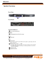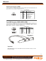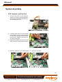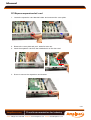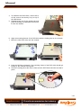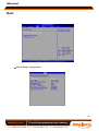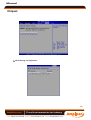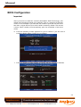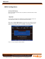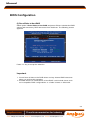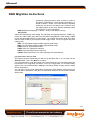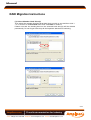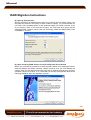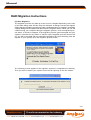
1
Manual
Impact 1015 1U rackmount computer user manual
Part No: 85080229 issue A1
Amplicon.com
IT and Instrumentation for industry
Sales: +44 (0) 1273 570 220 Website: www.amplicon.com Email: [email protected]
Manual
Safety Instructions
Before you unpack your computer system, ensure you carefully read
through this manual and follow any related safety or operational
instructions.
Only suitably qualified and experienced personnel should work inside the
computer.
Before commencing work within the computer ensure that the mains is
disconnected from the computer and any attached peripherals.
Operation of your computer
Before operating your computer please:
Read the equipment ratings plate and ensure that the mains circuit is
suitably rated to power the equipment, to avoid risk of overloading. Do
not use mains adaptors, or extenders.
Ensure that any cables connecting to the equipment are made safe and
do not present a tripping hazard.
To avoid risk of electric shock ensure that equipment is plugged into a
suitably earthed mains outlet. Only use the power cord supplied with your
computer or power supply unit. Do not continue to use the cable if it is
cut or damaged
---
Ensure the computer chassis is kept away from heat sources, such as
radiators and heating vents.
Computer chassis ventilation slots must be kept clear and not blocked.
Failure to do so is likely to cause the unit to overheat and become
unstable.
Avoid connecting the computer to an electrical supply which may have
unacceptable interruptions, surges, spikes or noise. We recommend the
use of an uninterruptible power supply (UPS), surge protector or mains
conditioner to address the problem.
Electrostatic Discharge Damage
When working on the inside of a computer system, you must be aware
that many of the components are electrostatic discharge sensitive (ESD).
These components can easily be damaged if suitable precautions are not
taken. ESD damage is not always immediately apparent and may result
in a failure many weeks later. When working on equipment we
recommend the use of an ESD mat and wrist strap.
Amplicon.com
IT and Instrumentation for industry
Sales: +44 (0) 1273 570 220 Website: www.amplicon.com Email: [email protected]
Manual
CONTENTS
Chapter 1 Getting Started ..................................................................................... 1-1
System Overview ............................................................................................... 1-2
System Specifications ........................................................................................ 1-6
Mainboard Layout ................................................................................................ 1-8
Chapter 2 Hardware Setup .................................................................................... 2-1
Quick Components Guide .................................................................................... 2-2
CPU (Central Processing Unit) ............................................................................ 2-3
Memory ................................................................................................................. 2-4
Power Supply ...................................................................................................... 2-6
Back Panel I/O ...................................................................................................... 2-7
Connector ............................................................................................................ 2-8
Jumper ................................................................................................................ 2-15
Slot ...................................................................................................................... 2-16
System Assembly Flowchart ........................................................................... 2-18
System Assembly .............................................................................................. 2-19
Rack Mounting .................................................................................................... 2-30
Chapter 3 BIOS Setup ............................................................................................. 3-1
Entering Setup ..................................................................................................... 3-2
The Menu Bar ...................................................................................................... 3-4
Main ...................................................................................................................... 3-5
Advanc ed ............................................................................................................ 3-6
Boot .................................................................................................................... 3-20
Security .............................................................................................................. 3-23
Chipset ............................................................................................................... 3-24
Exit ...................................................................................................................... 3-26
Appendix A Intel ICH9R SATA RAID ..................................................................... A-1
ICH9R Introduction ............................................................................................... A-2
BIOS Configuration .............................................................................................. A-3
Installing Driver .................................................................................................... A-9
Installing Software ............................................................................................ A-11
RAID Migration Instructions ............................................................................... A-15
Degraded RAID Array ........................................................................................ A-22
Amplicon.com
IT and Instrumentation for industry
Sales: +44 (0) 1273 570 220 Website: www.amplicon.com Email: [email protected]
Manual
Chapter 1
Getting Started
Thank you for choosing the Amplicon Impact 1015, a
high-performance 1U rackmount system from Amplicon.
Based on the innovative Intel® 3200 + ICH9R chipsets
for optimal system efficiency, th is system accommodates the latest Dual-Core Intel® Xeon® processor 3000
series, Quad-Core Intel® Xeon® processor 3200 series,
W olfdale and Yorkfield processors in LGA775 package and supports up to four 240-pin DDR2 667/800
DIMM slots to provide the maximum of 8GB memory
capacity.
W ith high scalability, reliability, ease of use, and overall
value, this system makes an ideal choice for value conscious customers.
1-1
Amplicon.com
IT and Instrumentation for industry
Sales: +44 (0) 1273 570 220 Website: www.amplicon.com Email: [email protected]
Manual
System Overview
Top View
3
4
5
6
8
2
7
1
1
Dual hotswappable HDD bays
2
Slim DVD /CDROM drive
3
PCI Express expansion slot
4
CPU soc ket
5
DIMM slots (x 4)
6
300W 1U Power Supply Unit (PSU)
7
Blower
8
Fan du ct
(LGA775)
1-2
Amplicon.com
IT and Instrumentation for industry
Sales: +44 (0) 1273 570 220 Website: www.amplicon.com Email: [email protected]
Manual
System Overview
Front View
1
2
Front Bezel
4
5
6 7
8
10
9
3
Slim DVD/CDROM drive
1
Slim DVD/CDROM drive
HDD bays
2
Hotswappable Hard Disk Drive bays
Ports
3
USB ports
LEDs
4
Power LED
This indicator shows the power status of the system. It glows (ON) when the
power is turned on.
5
Status LEDs of LAN1 / LAN2
1. The green LED is ON when there is an active connection on the LAN port.
2. This LED flashes when transmitting or receiving activities to or from the
system are detected.
6
System ID LED
7 System Alert LED
1-3
Amplicon.com
IT and Instrumentation for industry
Sales: +44 (0) 1273 570 220 Website: www.amplicon.com Email: [email protected]
Manual
System Overview
Buttons
8
9
System ID button
Power button
Press this button once to shut down the system, and then once to switch on.
10
System Reset button
Front Bezel LEDs
LED
Color
State
Description
Power
Blue
On
Legacy power on/ACPI S0 state
Blue
Blink
Sleep/ACPI S1, S4, S5 state
Off
Off
Power off
Green
On
LAN link
Green
Blink
LAN access activity
LAN1/LAN2 Activity
1-4
Amplicon.com
IT and Instrumentation for industry
Sales: +44 (0) 1273 570 220 Website: www.amplicon.com Email: [email protected]
Manual
System Overview
Rear View
Rear Bezel
1
3
2
4
5
1
PS/2 Keyboard/Mouse Connector
2
USB ports
3
Serial port
4
VGA port
5
LAN Jacks
Rear Bezel LEDs
LED
Color
Off
RJ45 NIC1 /
NIC2 Link Speed
Orange
(Left Side)
RJ45 NIC1 /
NIC2 Access
(Right Side)
LED State
On (steady state)
On (brighter & pulsing)
Green
Orange
Condition
LAN link is not established.
LAN link is established.
Thecomputer is communicating with another
computer on the LAN.
Off
10 Mbit/sec data rate is selected.
On
100 Mbit/sec data rate is selected.
On
1000 Mbit/sec data rate is selected.
1-5
Amplicon.com
IT and Instrumentation for industry
Sales: +44 (0) 1273 570 220 Website: www.amplicon.com Email: [email protected]
Manual
System Specifications
Proce ssor
- Support for Intel Core 2 Duo processors (default processor) and
Dual-Core Intel Xeon processor 3000 series, Quad-Core Intel Xeon
processor 3200 series, Wolfdale and Yorkfield processors in LGA775
package .
FSB
- 1333/ 1066/ 800 MHz
Chipset
- North Bridge: Intel 3200 chipset (Intel 3200/3210 supports PCI
Express graphics)
- South Bridge: Intel ICH9R chipset
M e mo r y
- 4 DDR2 667/800 DIMM slots (240pin / 1.8V)
- Up to 8GB memory capacity
LAN
- Intel 82573L Gigabit Ethernet controller (LAN1) & Intel 82566DM
Gigabit Ethernet controller (LAN2)
Floppy
- 1 floppy port
- Supports 1 FDD with 360KB, 720KB, 1.2MB, 1.44MB and 2.88MB
IDE
- 1 IDE port by ITE IT8213F
- Supports Ultra DMA 66/100/133 m ode
- Supports PIO, Bus Master operation mode
SATA
- 4 SATAII ports by ICH9R
- Supports storage and data transfers at up to 300MB/s
RAID
- Supports RAID 0, 1
1-6
Amplicon.com
IT and Instrumentation for industry
Sales: +44 (0) 1273 570 220 Website: www.amplicon.com Email: [email protected]
Manual
System Specifications
Graphics
- XGI Z7 graphics controller
- Onboard 16MB Video SDRAM
Connectors
Back Panel
- 1 PS/2 mouse port
- 1 PS/2 keyboard port
-
2
1
1
2
USB 2.0 ports
serial port
VGA port
Gigabit LAN jacks
Onboard Connectors
- 3 proprietary front panel connectors (optional)
- 3 USB 2.0 connectors (6 ports)
- 1 serial port connector
- 1 TPM connector
- 1 SPI Flash ROM connector (for debugging)
- 1 chassis intrusion connector
Slots
- 1 PCI Express x16 slot (with x8 signal)
- *1 PCI Express x4 slot
- *4 PCI slots (supports 3.3V/ 5V PCI bus interface)
(*Available on motherboard only)
Certification
- Safety: UL, CB, BSMI
- EMC: FCC Class A, CE Class A, BSMI
Chas sis
-
Form factor: 1U 19" rackmount
Externally hotswappable HDD bay x 2
Slim DVD/CDROM drive bay x 1
Full height PCI Express slot x 1
Chassis dimension: 428(W ) X 44.4(H) X 442(D) mm
Power Supply
- 300 Watt
PFC function: Yes
Form factor: SSI EPS 1U
Safety mark: UL, cUL, TUV, CE-mark, CB
1-7
Amplicon.com
IT and Instrumentation for industry
Sales: +44 (0) 1273 570 220 Website: www.amplicon.com Email: [email protected]
Manual
Mainboard Layout
COM2
SYS_FAN1
JUS B4
JAPP 2
FDD 1
FRON T_FAN1
J_IDE1
F PC1
SATA2
ITE
IT8213F
S ATA4
S ATA3
D_SATA1
SATA1
PCI1
JTPM1
JSPI1
PCI2
J_BOOT3 J_IPMB1
JINT1
J _S ATALED 1
D_SATALED1
Intel
ICH 9R
J_SMBUS1
PCI3
J_ICMB 1
BMC
Chip
J1
PCI4
J _B OOT2
JUSB3
XGI
Z7
JAPP 3
PCIE1
J_BOOT 1
JUSB2
PCIE2
LAN
Chip
J_VGA_EN1
BATT
+
CP U_FAN1
J_CMOS1
SYS_FAN2
D_SATA2
JLAN1
JLAN 2
Intel
3200
D_SATA LE D2
VGA 2
JAPP 1
COM1
DIMM_A 1
DIMM_A2
DIMM_B 1
JUSB1
DIMM_B2
RE AR_FAN 1
JPWR2
T: Mouse
B: Keyboard
JPWR1
ATX form factor Server Board
1-8
Amplicon.com
IT and Instrumentation for industry
Sales: +44 (0) 1273 570 220 Website: www.amplicon.com Email: [email protected]
Manual
Chapter 2
Hardware Setup
Refer to the system assembly flowchart and the chart
below to determine the proper sequence of removing
or installing components to the server.
Mainboard Hardware
CPU, Memory, Power Supply, Back
Panel, Connector, Jumper, Slot
Chassis Cover
CPU, Cooler
System Assembly
Memory
Expansion Card
Sy st em
Hard Disk Drives
Slim DVD/CDROM Drive
Rack Mounting
Rail Set
Rack Mounting
2-1
Amplicon.com
IT and Instrumentation for industry
Sales: +44 (0) 1273 570 220 Website: www.amplicon.com Email: [email protected]
Manual
Quick Components Guide
JSPI1 , p.2-13
JTPM1 ,
p.2-14
JAPP2 , p.2-11
J_IDE1 ,
p.2-8
FRONT_FAN1 ,
p.2-10
JUSB4 ,
p.2-12
SYS_FAN1 ,
p.2-10
FDD1 ,
p.2-8
COM2 , p.2-12
PCI Slots
p.2-16
FPC1 , p.2-10
SATA1~4
,
p.2-9
D_SATA1 ,
p.2-9
J_BOOT3 ,
p.2-15
D_SATALED1 ,
p.2-9
JUSB2/3 ,
p.2-12
JAPP3 , p.2-11
,
JINT1 ,
p.2-10
J_IPMB1 , p.2-13
J_ICMB1 , p.2-13
J_BOOT2,
p.2-13
J_SMBUS1 ,
p.2-14
J1 , p.2-13
J_BOOT1 ,
p.2-13
PCI Express
Slots , p.2-16
J_VGA_EN1 ,
p.2-15
CPU_FAN1 ,
p.2-10
SYS_FAN2 ,
p.2-10
J_CMOS1 ,
p.2-15
D_SATA2 ,p.2-9
D_SATALED2 ,
p.2-9
CPU , p.2-3
DIMM Slots
p.2-4
,
JPWR2 ,
p.2-6
JPWR1 ,
p.2-6
REAR_FAN1 ,
p.2-10
Back Panel
I/O , p.2-7
JAPP1 , p.2-11
2-2
Amplicon.com
IT and Instrumentation for industry
Sales: +44 (0) 1273 570 220 Website: www.amplicon.com Email: [email protected]
Manual
CPU (Central Processing Unit)
This mainboard supports dual-core Intel® Xeon® processor 3000 series, quad-core
Intel® Xeon® processor 3200 series, W olfdale and Yorkfield processors in LGA775
package. W hen you install the CPU, make sure that you install the cooler to
prevent overheating. If you do not have the CPU cooler, consult your dealer
before turning on the computer.
Important
Overheating
Overheating will seriously damage the CPU and system. Always make sure
the cooling fan can work properly to protect the CPU from overheating. Make
sure that you apply an even layer of thermal paste (or thermal tape) between
the CPU and the heatsink to enhance heat dissipation.
Replaceing the CPU
While replacing the CPU, always turn off the power supply or unplug the
power supply’s power cord from the grounded outlet first to ensure the safety
of CPU.
Introduction to LGA 775 CPU
The pin-pad side of LGA 775
CPU.
Alignment Key
Yellow triangle is the Pin 1 indicator
The surface of LGA 775 CPU.
Remember to apply some thermal paste on it for better heat
dispersion.
Alignment Key
Yellow triangle is the Pin 1 indicator
2-3
Amplicon.com
IT and Instrumentation for industry
Sales: +44 (0) 1273 570 220 Website: www.amplicon.com Email: [email protected]
Manual
Memory
These DIMM slots are intended for system memory modules.
DDR2
240-pin, 1.8V
64x2=128 pin
56x2=112 pin
Dual-Channel Mode Population Rule
In Dual-Channel mode, the memory modules can transmit and receive data with two
data bus lines simultaneously. Dual-Channel mode is enabled when the installed
memory capacities of both DIMM channels are equal. If different speed DIMMs are
used between channels, the slowest memory timing will be used.
Dual-Channel mode can be achieved with two, three or four DIMMs. To achieve DualChannel mode, the following conditions must be met:
*
*
*
*
Matched DIMM configuration in each channel
Same Density (128MB, 256MB, 512MB, etc.)
Matched in both Channel A and Channel B memory channels
Populate symmetrical memory slots (Slot 1 or Slot 2)
Configurations that do not match the above conditions will revert to Single-Channel
mode.
2 DIMM s
1GB
DIMM_A1
DIMM_A2
1GB
DIMM_B1
DIMM_B2
512MB
512MB
DIMM_A1
3 DIMM s
1GB
DIMM_A2
DIMM_B1
DIMM_B2
4 DIMM s
512MB
1GB
DIMM_A1
512MB
1GB
DIMM_B1
DIMM_B2
DIMM_A2
Installed
Empty
2-4
Amplicon.com
IT and Instrumentation for industry
Sales: +44 (0) 1273 570 220 Website: www.amplicon.com Email: [email protected]
Manual
Memory
Installing Memory Modules
1. The memory module has only one notch on the center and will only fit in the right
orientation.
2. Insert the memory module vertically into the DIMM slot. Then push it in until the
golden finger on the memory module is deeply inserted in the DIMM slot.
Important
You can barely see the golden finger if the memory module is properly inserted
in the DIMM slot.
3. The plastic clip at each side of the DIMM slot will automatically close.
Volt
Notch
2-5
Amplicon.com
IT and Instrumentation for industry
Sales: +44 (0) 1273 570 220 Website: www.amplicon.com Email: [email protected]
Manual
Power Supply
24-Pin System Power Connector: JPWR2
This connector allows you to connect a 24-pin power supply. To
connect the 24-pin power supply, make sure the power supply
connector is inserted in the proper orientation and the pins are
aligned. Then push down the power supply firmly into the connector.
pin 12
You may use the 20-pin power supply as well. If you’d like to use the
20-pin power supply, please align your power supply connector
with pin 1 & pin 13. There is also a foolproof design on pin 11, 12, 23
& 24 to avoid wrong installation.
pin 13
Pin Definition
JPWR2
24
13
12
1
PIN
SIGNAL
PIN
SIGNAL
1
+3.3V
13
+3.3V
2
3
+3.3V
GND
14
15
-12V
GND
4
5
+5V
GND
16
17
PS-ON#
GND
6
7
+5V
GND
18
19
GND
GND
8
9
PWR OK
5VSB
20
21
Res
+5V
10
11
+12V
+12V
22
23
+5V
+5V
12
+3.3V
24
GND
8-Pin CPU Power Connector: JPWR1
This connector provides 12V power output to the CPU.
Pin Definition
JPWR1
1
4
5
8
PIN
SIGNAL
PIN
SIGNAL
1
2
GND
GND
5
6
+12V
+12V
3
4
GND
GND
7
8
+12V
+12V
Important
1. Make sure that all connectors are connected to proper power supplies to
ensure stable operation of the mainboard.
2. Power supply of 3 0 0 watts (and above) is highly recommended for system
stability.
2-6
Amplicon.com
IT and Instrumentation for industry
Sales: +44 (0) 1273 570 220 Website: www.amplicon.com Email: [email protected]
Manual
Back Panel I/O
Mouse
Keyboard USB Ports
Serial Port
VGA Port
LAN Jacks
M ouse/Keyboard
The standard PS/2® mouse/keyboard DIN connector is for a PS/2® mouse/keyboard.
USB Port
The USB (Universal Serial Bus) port is for attaching USB devices such as keyboard,
mouse, or other USB-compatible devices.
Serial Port
The serial port is a 16550A high speed communications port that sends/ receives 16
bytes FIFOs. You can attach a serial mouse or other serial devices directly to the
connector.
VGA Port
The DE-15 female connector is provided for monitor.
LAN
The standard RJ-45 LAN jack is for connection to the Local Area Network (LAN). You
can connect a network cable to it.
Link/Active Indicator
Mode Indicator
RJ-45 LAN Jack
LED
Color
LED State
Off
Left
Orange
On (steady state)
Condition
LAN link is not established.
LAN link is established.
On (brighter & pulsing) The computer is communicating with another computer on the LAN.
Green
Right
Orange
Off
10 Mbit/sec data rate is selected.
On
100 Mbit/sec data rate is selected.
On
1000 Mbit/sec data rate is selected.
2-7
Amplicon.com
IT and Instrumentation for industry
Sales: +44 (0) 1273 570 220 Website: www.amplicon.com Email: [email protected]
Manual
Connector
Floppy Disk Drive Connector: FDD1
This connector supports 360KB, 720KB, 1.2MB, 1.44MB or 2.88MB floppy disk drive.
FDD1
IDE Connector: J_IDE1
This connector supports IDE hard disk drives, optical disk drives and other IDE devices.
J_IDE1
Important
If you install two IDE devices on the same cable, you must configure the
drives separately to master / slave mode by setting jumpers. Refer to IDE
dev ic e’s doc umentation s upplied by the vendors for jumper s etting
instructions.
2-8
Amplicon.com
IT and Instrumentation for industry
Sales: +44 (0) 1273 570 220 Website: www.amplicon.com Email: [email protected]
Manual
SAS Connector: D_SATA1, D_SATA2
These connectors are designed to connect Serial ATA devices only.
SAS LED Connector: D_SATALED1, D_SATALED2
These connectors are used to connect external LEDs to show the status of the SATA
HDDs attached to the D_SATA1 & D_SATA2. The D_SATALED1 is intended for the
D_SATA1 and the D_SATALED2 is made for the D_SATA2. W hen a SATA HDD is
attached to the SAS connector, the LED connecting pin 1 & 2 will glow. W hen HDD
activity/access is detected, the LED connecting pin 3 & 4 will blink.
D_SATALED1,
D_SATA1,
D_SATALED2
D_SATA2
1
Pin Definition
PIN
SIGNAL
1
+3.3V
2
3
GND
+3.3V
4
SATARead
Serial ATA Connector: SATA1 ~ SATA4
This connector is a high-speed Serial ATA interface port. Each connector can connect to one Serial ATA device.
SATA1 SATA2
SATA3 SATA4
Important
Please do not fold the Serial ATA cable into 90-degree angle. Otherwise,
data loss may occur during transmission.
2-9
Amplicon.com
IT and Instrumentation for industry
Sales: +44 (0) 1273 570 220 Website: www.amplicon.com Email: [email protected]
Manual
DVD/CDROM Connector: FPC1 (Optional)
This connector is designed to connect slim DVD/CD-ROM drive.
FPC1
Chassis Intrusion Switch Connector: JINT1
This connector connects to the chassis intrusion switch cable. If the chassis is
opened, the chassis intrusion mechanism will be activated. The system will record
this status and show a warning message on the screen. To clear the warning, you
must enter the BIOS utility and clear the record.
CINTRU
GND
1
2
JINT1
Fan Power Connector:
CPU_FAN1, SYS_FAN1/2, FRONT_FAN1, REAR_FAN1
The fan power connectors support system cooling fan with +12V. W hen connecting
the wire to the connectors, always note that the red wire is the positive and should
be connected to the +12V; the black wire is Ground and should be connected to GND.
If the mainboard has a System Hardware Monitor chipset onboard, you must use a
specially designed fan with speed sensor to take advantage of the CPU fan control.
CONTROL
SENSOR
+1 2V
GND
CONTROL
SENSOR
+1 2V
GND
CPU_FAN1,
SYS_FAN1,
FRONT_FAN1
SYS_FAN2,
REAR_FAN1
Important
1. Please refer to the recommended CPU fans at processor’s official website
or consult the vendors for proper CPU cooling fan.
2. Users are suggested to enter the BIOS Setup Utility to set up the Smart Fan
Control function.
2-10
Amplicon.com
IT and Instrumentation for industry
Sales: +44 (0) 1273 570 220 Website: www.amplicon.com Email: [email protected]
Manual
Front Panel Connector: JAPP1, JAPP2, JAPP3 (Optional)
These are proprietary front panel connectors that provide I2C bus connection, serial
signal connection, and electrical connection to the front panel switches/LEDs.
JAPP1 Pin Definition
JAPP1
14
2
13
1
PIN
SIGNAL
PIN
SIGNAL
1
+5VSB
2
GND
3
RESET+
4
GND
5
POWER+
6
GND
7
COM2 RXD
8
GND
9
COM2 TXD
10
NC
11
ATX PWR OK
12
GND
13
ID_LED+
14
ID_LED-
JAPP2 Pin Definition
JAPP2
6
5
2
1
PIN
SIGNAL
1
2
+5VSB
GND
3
4
I2C_DATA
ID_LED+
5
6
I2C_CLK
ID_LED-
JAPP3 Pin Definition
JAPP3
1
19
PIN
SIGNAL
PIN
SIGNAL
1
Power LED +
2
SYS_LED +
3
Power LED -
4
SYS_LED -
5
Power Button +
6
LAN1_LED +
7
PowerButton -
8
LAN1_LED -
9
ID LED +
10
LAN2_LED +
11
ID LED -
12
LAN2_LED -
13
ID Button +
14
Reset +
15
ID Button -
16
Reset -
17
HDD LED +
18
HDD LED -
19
+5VSB
20
+5VSB
2
20
2-11
Amplicon.com
IT and Instrumentation for industry
Sales: +44 (0) 1273 570 220 Website: www.amplicon.com Email: [email protected]
Manual
Serial Port Connector: COM2
This connector is a 16550A high speed communications port that sends/receives 16
bytes FIFOs. You can attach a serial device to it.
Pin Definition
PIN
1
2
3
4
5
6
7
8
9
COM2
9
1
2
SIGNAL
DESCRIPTION
DCD
SIN
SOUT
DTR
GND
DSR
RTS
CTS
RI
Data Carry Detect
Serial In or Receive Data
Serial Out or Transmit Data
Data Terminal Ready
Ground
Data Set Ready
Request To Send
Clear To Send
Ring Indicate
Front USB Connector: JUSB2, JUSB3, JUSB4
This connector, compliant with Intel® I/O Connectivity Design Guide, is ideal for connecting high-speed USB interface peripherals such as USB HDD, digital cameras,
M P3 players, printers, modems and the like.
Pin Definition
JUSB2/3
1
2
9
10
JUSB4
2
1
10
9
PIN
SIGNAL
PIN
SIGNAL
1
VCC
2
VCC
3
USB0-
4
USB1-
5
USB0+
6
USB1+
7
GND
8
GND
9
Key (no pin)
10
USBOC
USB 2.0 Bracket
(Optional)
Important
Note that the pins of VCC and GND must be connected correctly to avoid
possible damage.
2-12
Amplicon.com
IT and Instrumentation for industry
Sales: +44 (0) 1273 570 220 Website: www.amplicon.com Email: [email protected]
Manual
SPI Flash ROM Connector: JSPI1
This connector is used to flash SPI flash ROM.
Pin Definition
JSPI1
2
1
10
9
Pin
Description
Pin
Description
1
VCC3_SB
2
VCC3_SB
3
SPI_MISO_F
4
SPI_MOSI_F
5
SPI_CS0_F#
6
SPI_CLK_F
7
GND
8
GND
9
SPI_HOLD#
10
NC
BMC Connector: J_BOOT1, J_BOOT2, J_IPMB1, J_ICMB1, J1
These connec tors are used to control the H8 BMC (Baseboard Management
Controller).
J_BOOT1
1
J_BOOT2
3
J_IPMB1
1
Pin Definition
1
Pin Definition
3
Pin Definition
PIN
SIGNAL
PIN
SIGNAL
PIN
SIGNAL
1
2
BOOT_TXD_CON
BOOT_RXD_CON
1
2
Boot Mode
GND
1
IPMB_DATA
3
GND
2
3
GND
IPMB_CLK
J1
J_ICMB1
3
1
2
13
14
1
Pin Definition
Pin Definition
PIN
SIGNAL
PIN
SIGNAL
BMC_RXD0
1
ETCK
2
GND
BMC_TXD0
ICMB_EN
3
ETRST#
4
GND
5
ETDO
6
GND
7
H2C_RES#
8
3.3V DUAL
9
ETMS
10
GND
11
ETDI
12
GND
13
H8_RESET#
14
GND
PIN
SIGNAL
1
2
3
2-13
Amplicon.com
IT and Instrumentation for industry
Sales: +44 (0) 1273 570 220 Website: www.amplicon.com Email: [email protected]
Manual
I2C Bus Connector: J_SMBUS1
The mainboard provides one I2C (also known as I2C) Bus connector for users to
connect System Management Bus (SMBus) interface.
Pin Definition
J_SMBUS1
1
PIN
SIGNAL
1
2
SMB_ICH_ALERT#
SMB_ICH_CLK
3
SMB_ICH_DATA
TPM Connector: JTPM1 (Optional)
This connector connects to an optional TPM (Trusted Platform Module). Please refer
to the TPM security platform manual for more details.
JTPM 1
13
14
1
2
PIN
1
SIGNAL
LCLK
DESCRIPTION
LPC clock
PIN
2
SIGNAL
3V dual/3V_STB
DESCRIPTION
3V dual or 3V standby power
3
5
LRST#
LAD0
LPC reset
LPC address & data pin0
4
6
VCC3
SIRQ
3.3V power
Serial IRQ
7
9
LAD1
LAD2
LPC address & data pin1
LPC address & data pin2
8
10
VCC5
KEY
5V power
No pin
11
13
LAD3
LFRAME#
LPC address & data pin3
LPC Frame
12
14
GND
GND
Ground
Ground
2-14
Amplicon.com
IT and Instrumentation for industry
Sales: +44 (0) 1273 570 220 Website: www.amplicon.com Email: [email protected]
Manual
Jumper
VGA Jumper: J_VGA_EN1
This jumper is used to enable or disable the onboard VGA controller.
3
3
1
1
Enable
Disable
1
J_VGA_EN1
BIOS Recovery Jumper: J_BOOT3
Users can short connect pin#2-3 to recover the system BIOS with a Recovery
Floppy. W hen the system is done with the job, the buzzer will beep to remind the user
to set the jumper to its normal state (pin#1-2 short connected).
1
1
3
J_BOOT3
1
3
Normal
Recovery
Clear CMOS Jumper: J_CMOS1
There is a CMOS RAM onboard that has a power supply from an external battery to
keep the data of system configuration. W ith the CMOS RAM, the system can automatically boot OS every time it is turned on. If you want to clear the system configuration,
set the jumper to clear data.
1
1
J_CMOS1
3
Keep Data
1
3
Clear Data
Important
You can clear CMOS by shorting 2-3 pin while the system is off. Then return
to 1-2 pin position. Avoid clearing the CMOS while the system is on; it will
damage the mainboard.
2-15
Amplicon.com
IT and Instrumentation for industry
Sales: +44 (0) 1273 570 220 Website: www.amplicon.com Email: [email protected]
Manual
Slot
PCI (Peripheral Component Interconnect) Express Slot
The PCI Express slot supports the PCI Express interface expansion card.
The standard PCI Express x16 slot supports up to 4.0 GB/s transfer rate.
But the onboard PCI Express x16 slot only supports x8 signal with up to
2.0 GB/s transfer rate.
PCI Express x16 Slot
Important
When adding or removing expansion cards, make sure that you unplug the
power supply first. Meanwhile, read the documentation for the expansion
card to configure any necessary hardware or software settings for the expansion card, such as jumpers, switches or BIOS configuration.
2-16
Amplicon.com
IT and Instrumentation for industry
Sales: +44 (0) 1273 570 220 Website: www.amplicon.com Email: [email protected]
Manual
PCI Interrupt Request Routing
The IRQ, acronym of interrupt request line and pronounced I-R-Q, are hardware lines
over which devices can send interrupt signals to the microprocessor. The PCI IRQ
pins are typically connected to the PCI bus pins as follows:
DEVICE
Interrupt
ID Select
REQ / GNT
XGI Z7
PCI_PIRQ # 0
PCI_AD18
IT8213F
PCI_PIRQ # 2
PCI_AD19
PCI_REQ# 2 / PCI_GNT# 2
PCI Slot 1
PCI_PIRQ # 0
PCI_AD20
PCI_REQ# 0 / PCI_GNT# 0
PCI_AD21
PCI_REQ# 1 / PCI_GNT# 1
PCI_AD22
PCI_REQ# 3 / PCI_GNT# 3
PCI_PIRQ # 1
PCI_PIRQ # 2
PCI_PIRQ # 3
PCI Slot 2
PCI_PIRQ # 3
PCI_PIRQ # 0
PCI_PIRQ # 1
PCI_PIRQ # 2
PCI Slot 3
PCI Slot 4
PCI_PIRQ # 2
PCI_PIRQ # 3
or
PCI_PIRQ # 0
ARBITER_REQ# 1
PCI_PIRQ # 1
ARBITER_GNT# 1
PCI_PIRQ # 1
PCI_AD23
ARBITER_REQ# 2
PCI_PIRQ # 2
&
PCI_PIRQ # 3
ARBITER_GNT# 2
PCI_PIRQ # 0
2-17
Amplicon.com
IT and Instrumentation for industry
Sales: +44 (0) 1273 570 220 Website: www.amplicon.com Email: [email protected]
Manual
System Assembly Flowchart
The following flowchart shows basic system assembly procedures. Please note
that always wear anti-static gloves when handling electrical components and exercise caution during the installation process. For more information, contact your local
dealer or experienced technician.
START
REMOVE CHASSIS COVER
INSTALL
CPU & HEATSINK
INSTALL
MEMORY MODULES
INSTALL
PCI EXPANSION CARDS
INSTALL
HARD DISK DRIVES
CHECK IF ALL PARTS
ARE PROPERLY CONNECTED
REPLACE
CHASSIS COVER
FINISH
2-18
Amplicon.com
IT and Instrumentation for industry
Sales: +44 (0) 1273 570 220 Website: www.amplicon.com Email: [email protected]
Manual
System Assembly
Chassis Cover
1. Unscrew the chassis cover.
2. Press the release button and slide
the chassis cover backwards to
remove it from the chassis.
3. Lift the chassis cover up to remove it from the chassis.
4. Follow the above procedures in reverse order to replace the chassis cover if
nec essary.
Important
Before you remove or install any components, make sure the server is not
turned on or connected to the AC power.
2-19
Amplicon.com
IT and Instrumentation for industry
Sales: +44 (0) 1273 570 220 Website: www.amplicon.com Email: [email protected]
Manual
System Assembly
CPU, Heatsink, and Fan Duct
1. On top of the CPU is a fan duct designed to enhance heat dissipation
of the CPU. Remove the fan duct before installing the CPU.
2. Locate the CPU socket. The CPU socket
has a plastic cap on it to protect the
contact from damage. Before installing the CPU, always cover it to protect the socket pins.
3. Remove the plastic cap from the load
plate. The pins of the socket reveal.
4. Raise the load lever up to its full extent. 5. Open the load plate.
2-20
Amplicon.com
IT and Instrumentation for industry
Sales: +44 (0) 1273 570 220 Website: www.amplicon.com Email: [email protected]
Manual
System Assembly
6. After confirming the CPU direction (indicated below with red circles) for correct
mating, put down the CPU in the socket housing frame. Note that the alignment
keys are matched.
7. Visually inspect if the CPU is seated well into the socket. If not, take out the CPU
with pure vertical motion and reinstall.
Alignment Key
Yellow triangle is the Pin 1 indicator
8. Cover the load plate onto the package.
9. Press down the load lever lightly onto the load plate and then secure the lever
with the hook under the retention tab.
10. Place the heatsink on top of the CPU and secure the screws on both sides.
2-21
Amplicon.com
IT and Instrumentation for industry
Sales: +44 (0) 1273 570 220 Website: www.amplicon.com Email: [email protected]
Manual
System Assembly
Memory
1. Locate the DIMM slots on the mainboard. Flip open the retaining clip at each side
of the DIMM slot.
2. Align the notch on the DIMM with the break on the slot. Insert the DIMM vertically
into the DIMM slot. Then push it in until the golden finger on the DIMM is deeply
inserted in the DIMM slot. The retaining clip at each side of the DIMM slot will
automatically close.
3. Follow the same procedures to install
more memory modules if necessary.
4. Replace the fan duct on top of the
heatsink and the memory DIMMs.
Note: To ensure proper cooling,
make sure the heatsink & the fan
duct are properly installed.
2-22
Amplicon.com
IT and Instrumentation for industry
Sales: +44 (0) 1273 570 220 Website: www.amplicon.com Email: [email protected]
Manual
Dual-Channel Mode Population Rule
In Dual-Channel mode, the memory modules can transmit and receive data with two
data bus lines simultaneously. Dual-Channel mode is enabled when the installed
memory capacities of both DIMM channels are equal. If different speed DIMMs are
used between channels, the slowest memory timing will be used.
Dual-Channel mode can be achieved with two, three or four DIMMs. To achieve DualChannel mode, the following conditions must be met:
*
*
*
*
Matched DIMM configuration in each channel
Same Density (128MB, 256MB, 512MB, etc.)
Matched in both Channel A and Channel B memory channels
Populate symmetrical memory slots (Slot 1 or Slot 2)
Configurations that do not match the above conditions will revert to Single-Channel
mode.
2 DIMM s
1GB
DIMM_A1
DIMM_A2
1GB
DIMM_B1
DIMM_B2
3 DIMM s
512MB
512MB
1GB
DIMM_A1
DIMM_A2
DIMM_B1
DIMM_B2
4 DIMM s
512MB
1GB
DIMM_A1
DIMM_A2
512MB
1GB
DIMM_B1
DIMM_B2
Installed
Empty
2-23
Amplicon.com
IT and Instrumentation for industry
Sales: +44 (0) 1273 570 220 Website: www.amplicon.com Email: [email protected]
Manual
PCI Express expansion slot / card
1. Locate the expansion card bracket holder and unscrew the cover plate.
2. Remove the cover plate and put it aside for later use.
3. Insert the expansion card into the intended slot on the riser card.
4. Screw to secure the expansion card bracket.
2-24
Amplicon.com
IT and Instrumentation for industry
Sales: +44 (0) 1273 570 220 Website: www.amplicon.com Email: [email protected]
Manual
Hard Disk Drive
1. To release the hot-swapping HDD
tray, first press the release button.
2. Pull the tray lever outwards and gently pull the tray out of the bay.
2
1
3. Unscrew and remove the HDD tray.
2-25
Amplicon.com
IT and Instrumentation for industry
Sales: +44 (0) 1273 570 220 Website: www.amplicon.com Email: [email protected]
Manual
4. Install the HDD and secure it with four screws supplied by the HDD vendor.
5. Insert the HDD tray into the bay and push it backwards until it hits the end. If the
HDD tray is correctly installed, the adapter at the rear should get connected to the
onboard SAS connector (see page 2-9).
6. Push the tray lever back in place.
1
2
2-26
Amplicon.com
IT and Instrumentation for industry
Sales: +44 (0) 1273 570 220 Website: www.amplicon.com Email: [email protected]
Manual
Slim DVD /CDROM Drive
1. Take out your slim DVD/CDROM drive and the caddy kit (mounting frames and adapter).
2. Screw the mounting frames to the sides of the DVD drive as shown below.
3. Screw the adapter to the rear of the DVD drive.
2-27
Amplicon.com
IT and Instrumentation for industry
Sales: +44 (0) 1273 570 220 Website: www.amplicon.com Email: [email protected]
Manual
4. To install the slim DVD drive, users have to
at first remove the dummy tray on top of
the HDD drives.
5. Simultaneously pull up the locking tab and
push the dummy tray backwards to remove
it from the chassis.
6. Align the mounting frames of the DVD drive with the locking tabs on the chassis.
7. Mount the slim DVD drive onto the chassis.
8. Push the DVD drive forwards. The mounting frames of the DVD drive should get
locked by the chassis locking tabs.
9. Check the locking tab at the rear to make sure the DVD drive has been secured in
place.
2
1
2-28
Amplicon.com
IT and Instrumentation for industry
Sales: +44 (0) 1273 570 220 Website: www.amplicon.com Email: [email protected]
Manual
10. Locate the FPC socket on the mainboard.
T he f li p lock of the FPC
socket is in UNLOCK state
when flipped inwards.
T he flip loc k of the FPC
socket is in LOCK st at e
when flipped outwards.
11. Flip the flip lock inwards to unlock the socket.
12. Insert the FPC cable into the socket (with the blank side of the cable facing
down .)
13. Flip the flip lock outwards to lock the FPC cable in place.
14. The DVD drive adapter has one identical FPC socket. Follow the above procedures to connect the other end of the FPC cable to the DVD drive adapter.
15. Make sure that the flip lock has been flipped outwards to lock the FPC cable in
place.
2-29
Amplicon.com
IT and Instrumentation for industry
Sales: +44 (0) 1273 570 220 Website: www.amplicon.com Email: [email protected]
Manual
Rack Mounting
Rail Set
1. The rail set includes two rails and two L-shaped brackets.
2. Fasten 4 screws (2 on each side) to attach the rails onto the chassis.
2-30
Amplicon.com
IT and Instrumentation for industry
Sales: +44 (0) 1273 570 220 Website: www.amplicon.com Email: [email protected]
Manual
Rack Mounting
Rack Mounting
1. Mount the system onto the rack.
2. Hold the system firmly and screw to secure the system to the rack.
Note: Make sure that you hold the system firmly while screwing the system
to the rack.
2-31
Amplicon.com
IT and Instrumentation for industry
Sales: +44 (0) 1273 570 220 Website: www.amplicon.com Email: [email protected]
Manual
Rack Mounting
3. Mount the L-shaped bracket onto the
rail.
4. Screw the L-shaped bracket to the rack.
5. Screw the L-shaped bracket to the rail.
6. Follow the above procedures in reverse order to dismount the system from the
rack if necessary.
2-32
Amplicon.com
IT and Instrumentation for industry
Sales: +44 (0) 1273 570 220 Website: www.amplicon.com Email: [email protected]
Manual
Chapter 3
BIOS Setup
This chapter provides information on the BIOS Setup
program and allows you to configure the system for
optimum use.
You may need to run the Setup program when:
An error message appears on the screen during the
system booting up, and requests you to run SETUP.
You want to change the default settings for customized features.
3-1
Amplicon.com
IT and Instrumentation for industry
Sales: +44 (0) 1273 570 220 Website: www.amplicon.com Email: [email protected]
Manual
Entering Setup
Power on the computer and the system will start POST (Power On Self Test) process.
W hen the message below appears on the screen, press <Del> key to enter Setup.
Press Del to enter SETUP
If the message disappears before you respond and you still wish to enter Setup,
restart the system by turning it OFF and On or pressing the RESET button. You may
also restart the system by simultaneously pressing <Ctrl>, <Alt>, and <Delete> keys.
Important
1. The items under each BIOS category described in this chapter are under
continuous update for better system performance. Therefore, the description may be slightly different from the latest BIOS and should be held for
reference only.
2. Upon boot-up, the 1st line appearing after the memory count is the BIOS
version.
3-2
Amplicon.com
IT and Instrumentation for industry
Sales: +44 (0) 1273 570 220 Website: www.amplicon.com Email: [email protected]
Manual
Entering Setup
Control Keys
< ↑>
Move to the previous item
< ↓>
Move to the next item
< ←>
Move to the item in the left hand
< →>
Move to the item in the right hand
<Enter>
Select the item
<Esc>
Jumps to the Exit menu or returns to the main menu from a
submenu
<+/PU>
Increase the numeric value or make changes
<-/PD>
Decrease the numeric value or make changes
<F8>
Load Optimized Defaults
<F9>
Load Fail-Safe Defaults
<F10>
Save all the CMOS changes and exit
Getting Help
After entering the Setup menu, the first menu you will see is the Main Menu.
M ain M enu
The main menu lists the setup functions you can make changes to. You can use the
arrow keys ( ↑↓ ) to select the item. The on-line description of the highlighted setup
function is displayed at the bottom of the screen.
Sub-M enu
If you find a right pointer symbol (as shown in the right view)
appears to the left of certain fields that means a sub-menu
can be launched from this field. A sub-menu contains additional options for a field parameter. You can use arrow keys
( ↑↓ ) to highlight the field and press <Enter> to call up the sub-menu. Then you can
use the control keys to enter values and move from field to field within a sub-menu.
If you want to return to the main menu, just press the <Esc >.
General Help <F1>
The BIOS setup program provides a General Help screen. You can call up this screen
from any menu by simply pressing <F1>. The Help screen lists the appropriate keys
to use and the possible selections for the highlighted item. Press <Esc> to exit the
Help screen.
3-3
Amplicon.com
IT and Instrumentation for industry
Sales: +44 (0) 1273 570 220 Website: www.amplicon.com Email: [email protected]
Manual
The Menu Bar
Main
Use this menu for basic system configurations, such as time, date etc.
Advanced
Use this menu to set up the items of special enhanced features.
Boot
Use this menu to specify the priority of boot devices.
Security
Use this menu to set supervisor and user passwords.
Chipset
This menu controls the advanced features of the onboard Northbridge and Southbridge.
Exit
This menu allows you to load the BIOS default values or factory default settings into
the BIOS and exit the BIOS setup utility with or without changes.
3-4
Amplicon.com
IT and Instrumentation for industry
Sales: +44 (0) 1273 570 220 Website: www.amplicon.com Email: [email protected]
Manual
Main
AM I BIOS, Processor, System M emory
These items show the firmware and hardware specifications of your system. Read
only.
System Time
This setting allows you to set the system time. The time format is <Hour> <Minute>
<Second>.
System Date
This setting allows you to set the system date. The date format is <Day>, <Month>
<Date> <Year>.
3-5
Amplicon.com
IT and Instrumentation for industry
Sales: +44 (0) 1273 570 220 Website: www.amplicon.com Email: [email protected]
Manual
Advanced
For mainboards
3-6
Amplicon.com
IT and Instrumentation for industry
Sales: +44 (0) 1273 570 220 Website: www.amplicon.com Email: [email protected]
Manual
Advanced
CPU Configuration
Execute Disable Bit Capability
Intel's Execute Disable Bit functionality can prevent certain classes of malicious
"buffer overflow" attacks when combined with a supporting operating system.
This functionality allows the processor to classify areas in memory by where
application code can execute and where it cannot. W hen a malicious worm
attempts to insert code in the buffer, the processor disables code execution,
preventing damage or worm propagation.
Core M ulti-Processing
CMP (Core Multi Processing) is the ability to have many independent processing
cores on a single die, each with their own L1 Code & Data caches, Local APICs
& thermal controls, while having a shared L2 cache, power management & bus
interface. Intel multi-core architecture has a single Intel processor package that
contains two or more processor "execution cores," or computational engines to
enable enhanced performance and more-efficient simultaneous processing of
multiple tasks.
Intel(R) SpeedStep(tm) Tech
EIST (Enhanced Intel SpeedStep Technology) allows the system to dynamically
adjust processor voltage and core frequency, which can result in decreased
average power consumption and decreased average heat production.
3-7
Amplicon.com
IT and Instrumentation for industry
Sales: +44 (0) 1273 570 220 Website: www.amplicon.com Email: [email protected]
Manual
Advanced
IDE Configuration
SATA#1 Configuration, SATA#2 Configuration
These settings specify the operation modes of the SATA ports.
Configure SATA#1 as
s
This setting specifies the function of the on-chip SATA controller.
Primary/Secondary/Third/Fourth/Fifth/Sixth IDE Master/Slave
3-8
Amplicon.com
IT and Instrumentation for industry
Sales: +44 (0) 1273 570 220 Website: www.amplicon.com Email: [email protected]
Manual
Advanced
[Type]
Press PgUp/<+> or PgDn/<-> to select
[Manual], [None] or [Auto] type. Note that the
specifications of your drive must match with
the drive table. The hard disk will not work
properly if you enter improper information for
this category. If your hard disk drive type is
not matched or listed, you can use [Manual] to
define your own drive type manually.
[LBA/Large Mode]
Enabling LBA causes Logical Block Addressing to be used in place of Cylinders,
Heads and Sectors
[Block(Multi-Sector Transfer)] Any selection except Disabled determines
the number of sectors transferred per block
[PIO Mode]
Indicates the type of PIO (Programmed Input/
Output)
[DMA Mode]
Indicates the type of Ultra DMA
[S.M.A.R.T.]
This allows you to activate the S.M.A.R.T.
(Self-Monitoring Analysis & Reporting
Technology) capability for the hard disks. S.
M.A.R.T is a utility that monitors your disk sta
tus to predict hard disk failure. This gives you
an opportunity to move data from a hard disk
that is going to fail to a safe place before the
hard disk becomes offline.
[32 Bit Data Transfer]
Enables 32-bit communication between
CPU and IDE card
Floppy Configuration
Floppy A, Floppy B
This setting allows you to set the type of floppy drives installed.
3-9
Amplicon.com
IT and Instrumentation for industry
Sales: +44 (0) 1273 570 220 Website: www.amplicon.com Email: [email protected]
Manual
Advanced
Onboard LANs Configuration
GbE LAN1 (82573) Controller, GbE LAN2 (82566) Controller
These settings disable/enable the specified LAN controllers.
GbE LAN1 (82573) Boot ROM, GbE LAN2 (82566) Boot ROM
The items enable or disable the initialization of the onboard LAN Boot ROMs
during bootup. Selecting [Disabled] will speed up the boot process.
GbE Wake Up From S5
This field specifies whether the system will be awakened from power saving modes when activity or input signal of onboard LAN is detected.
3-10
Amplicon.com
IT and Instrumentation for industry
Sales: +44 (0) 1273 570 220 Website: www.amplicon.com Email: [email protected]
Manual
Advanced
Super IO Configuration
Onboard Floppy Controller
This setting disables/enables the onboard floppy disk drive controller.
Serial Port 1 Address, Serial Port 2 Address
Select an address and a corresponding interrupt for the serial port 1/2.
3-11
Amplicon.com
IT and Instrumentation for industry
Sales: +44 (0) 1273 570 220 Website: www.amplicon.com Email: [email protected]
Manual
Advanced
Hardware Health Configuration (for mainboards without IPM I chip)
These items display the current status of all of the monitored hardware devices/
components such as voltages, temperatures and all fans’ speeds.
CPU FAN Mode Setting
This setting controls the Smart Fan feature. Smart Fan is an excellent feature
which will adjust the CPU/system fan speed automatically depending on the
current CPU/system temperature. Selecting [Smart Fan Mode] can prevent
the CPU from being damaged by overheating.
Front Fan PWM Output, System Fan1 & Fan2 PWM Output, Rear Fan
PWM Output
This setting allows users to control the fan speed by changing the duty
cycle of the fan PW M (Pulse-Width Modulation) output.
3-12
Amplicon.com
IT and Instrumentation for industry
Sales: +44 (0) 1273 570 220 Website: www.amplicon.com Email: [email protected]
Manual
Advanced
APM Configuration
Resume On Ring
An input signal on the serial Ring Indicator (RI) line (in other words, an incoming
call on the modem) awakens the system from a soft off state.
Resume On PME# of PCI Slots
W hen setting to [Enabled], this setting allows your system to be awakened from
the power saving modes through any PME (Power Management Event) on PCI
slots.
Resume On RTC Alarm
W hen [Enabled], your can set the date and time at which the RTC (real-time
clock) alarm awakens the system from suspend mode.
3-13
Amplicon.com
IT and Instrumentation for industry
Sales: +44 (0) 1273 570 220 Website: www.amplicon.com Email: [email protected]
Manual
Advanced
Event Log Configuration
View Event Log
Press [Enter] to view the contents of the DMI event log.
Mark All Events as Read
d
Press [Enter] and a screen pops up, asking users to confirm whether or not to
clear all DMI event logs immediately. Press [Y] and [Enter], the BIOS will clear all
DMI event logs right away.
Clear Event Log
W hen this setting is set to [Yes], the DMI event log will be cleared at next POST
stage. Then, the BIOS will automatically set this option to [No].
3-14
Amplicon.com
IT and Instrumentation for industry
Sales: +44 (0) 1273 570 220 Website: www.amplicon.com Email: [email protected]
Manual
Advanced
IPMI 2.0 Configuration (for mainboards with IPM I chip)
Status of BM C, BM C Firmware Version
These settings show the status of the BMC (Baseboard Management
Controller) chip and its firmware version. Read only.
View BM C System Event Log
Use this function to view system event logs recorded by BMC.
Clear BM C System Event Log
Use this function to clear system event logs recorded by BMC.
Set LAN Configuration
Channel Number, IP Address, M AC Address, Subnet Mask
k
Use these settings to set up the channel number, IP address, MAC address,
and IP subnet mask for your system network.
3-15
Amplicon.com
IT and Instrumentation for industry
Sales: +44 (0) 1273 570 220 Website: www.amplicon.com Email: [email protected]
Manual
Advanced
BMC Watch Dog Timer Action
The system watch-dog timer is a hardware timer that generates either an NMI or
a reset when the software that it monitors does not respond as expected each
time the watch dog polls it.
Notify BMC FAN Type
This setting specifies the BMC fan type.
Remote Access Configuration
Remote Access
The setting enables/disables the remote access function. W hen set to [Enabled],
us ers may c onfigure the f ollowing s ettings f or remote ac cess type and
parameters.
Serial Port Number, Base Address, IRQ, Serial Port M ode
Use these settings to configure ports for remote access.
Flow Control
Flow control is the process of managing the rate of data transmission between
two nodes. It’s the process of adjusting the flow of data from one device to
another to ensure that the receiving device can handle all of the incoming data.
This is particularly important where the sending device is capable of sending
data much faster than the receiving device can receive it.
Redirection After BIOS POST
This setting determines whether or not to keep terminals’ console redirection
running after the BIOS POST has booted.
3-16
Amplicon.com
IT and Instrumentation for industry
Sales: +44 (0) 1273 570 220 Website: www.amplicon.com Email: [email protected]
Manual
Advanced
Terminal Type
To operate the system’s console redirection, you need a terminal supporting
ANSI terminal protocol and a RS-232 null modem cable connected between the
host system and terminal(s). This setting specifies the type of terminal device
for console redirection.
VT-UTF8 Combo Key Support
This setting enables/disables the VT-UTF8 combination key support for ANSI/
VT100 terminals.
Sredir Memory Display Delay
Use this setting to set the delay in seconds to display memory information.
Trusted Computing
TCG/TPM Support
This setting controls the Trusted Platform Module (TPM) designed by the Trusted
Computing Group (TCG). TPMs are special-purpose integrated circuits (ICs)
built into a variety of platforms to enable strong user authentication and machine attestation—essential to prevent inappropriate access to confidential
and sensitive information and to protect against compromised networks. TPM
Services is now a new feature set in W indows Server "Longhorn" and W indows Vista.
Clearing the TPM
W hen the TPM is cleared, all the keys you previously had stored on your vault
will be lost. You should create an archive of your TPM Keys before clearing the
TPM. To recover your TPM keys, you will need to restore your keys from an
archive.
3-17
Amplicon.com
IT and Instrumentation for industry
Sales: +44 (0) 1273 570 220 Website: www.amplicon.com Email: [email protected]
Manual
Advanced
TPM Enable/Disable Status
This setting displays the TPM enable/disable status. Read only.
TPM Owner Status
This setting shows the TPM ownership. Read only.
USB Configuration
Legacy USB Support
Set to [Enabled] if you need to use any USB 1.1/2.0 device in the operating
system that does not support or have any USB 1.1/2.0 driver installed, such as
DOS and SCO Unix.
USB 2.0 Controller Mode
This setting specifies the operation mode of the onboard USB 2.0 controller.
BIOS EHCI Hand-Off
This setting allows you to enable or disable a workaround for operating systems without EHCI (Enhanced Host Controller Interface) hand-off support. The
Enhanced Host Controller Interface (EHCI) specification describes the registerlevel interface for a Host Controller for the Universal Serial Bus (USB) Revision
2.0.
3-18
Amplicon.com
IT and Instrumentation for industry
Sales: +44 (0) 1273 570 220 Website: www.amplicon.com Email: [email protected]
Manual
Advanced
USB Mass Storage Device Configuration
USB Mass Storage Reset Delay
This setting controls the number of seconds the POST waits for the USB
mass storage device after the start unit command is sent.
Emulation Type
This setting enables you to set the type of device you want the USB mass
storage device to emulate.
3-19
Amplicon.com
IT and Instrumentation for industry
Sales: +44 (0) 1273 570 220 Website: www.amplicon.com Email: [email protected]
Manual
Boot
Boot Settings Configuration
3-20
Amplicon.com
IT and Instrumentation for industry
Sales: +44 (0) 1273 570 220 Website: www.amplicon.com Email: [email protected]
Manual
Boot
Quick Boot
Enabling this setting will cause the BIOS power-on self test routine to skip some
of its tests during bootup for faster system boot.
Quiet Boot
This BIOS feature determines if the BIOS should hide the normal POST messages with the motherboard or system manufacturer's full-screen logo.
W hen it is enabled, the BIOS will display the full-screen logo during the boot-up
sequence, hiding normal POST messages.
When it is disabled, the BIOS will display the normal POST messages, instead of
the full-screen logo.
Please note that enabling this BIOS feature often adds 2-3 seconds of delay to
the booting sequence. This delay ensures that the logo is displayed for a
sufficient amount of time. Therefore, it is recommended that you disable this
BIOS feature for a faster boot-up time.
AddOn ROM Display M ode
This item is used to determine the display mode when an optional ROM is
initialized during POST. When set to [Force BIOS], the display mode used by AMI
BIOS is used. Select [Keep Current] if you want to use the display mode of
optional ROM.
Bootup Num-Lock
This setting is to set the Num Lock status when the system is powered on.
Setting to [On] will turn on the Num Lock key when the system is powered on.
Setting to [Off] will allow users to use the arrow keys on the numeric keypad.
PS/2 M ouse Support
Select [Enabled] if you need to use a PS/2-interfaced mouse in the operating
system.
Wait For ‘F1’ If Error
W hen this setting is set to [Enabled] and the boot sequence encounters an
error, it asks you to press F1. If disabled, the system continues to boot without
waiting for you to press any keys.
Hit ‘DEL’ Message Display
Set this option to [Disabled] to prevent the message as follows:
Hit Del if you want to run setup
It will prevent the message from appearing on the first BIOS screen when the
computer boots. Set it to [Enabled] when you want to run the BIOS Setup Utility.
Interrupt 19 Capture
Interrupt 19 is the software interrupt that handles the boot disk function. W hen
enabled, this BIOS feature allows the ROM BIOS of these host adaptors to
"capture" Interrupt 19 during the boot process so that drives attached to these
adaptors can function as bootable disks. In addition, it allows you to gain access to the host adaptor's ROM setup utility, if one is available.
3-21
Amplicon.com
IT and Instrumentation for industry
Sales: +44 (0) 1273 570 220 Website: www.amplicon.com Email: [email protected]
Manual
Boot
W hen disabled, the ROM BIOS of these host adaptors will not be able to "capture" Interrupt 19. Therefore, you will not be able to boot operating systems
from any bootable disks attached to these host adaptors. Nor will you be able to
gain access to their ROM setup utilities.
Boot Device Priority
1st Boot Device
The items allow you to set the sequence of boot devices where BIOS attempts
to load the disk operating system. First press <Enter> to enter the sub-menu.
Then you may use the arrow keys ( ↑↓ ) to select the desired device, then
press <+>, <-> or <PageUp>, <PageDown> key to move it up/down in the
priority list.
Removable Drives
1st Drive, 2nd Drive
This setting allows users to set the priority of the removable devices. First
press <Enter> to enter the sub-menu. Then you may use the arrow keys ( ↑↓ )
to select the desired device, then press <+>, <-> or <PageUp>, <PageDown>
key to move it up/down in the priority list.
3-22
Amplicon.com
IT and Instrumentation for industry
Sales: +44 (0) 1273 570 220 Website: www.amplicon.com Email: [email protected]
Manual
Security
Supervisor Password / Change Supervisor Password
Supervisor Password controls access to the BIOS Setup utility. These settings allow
you to set or change the supervisor password.
User Password / Change User Password / Clear User Password
User Password controls access to the system at boot. These settings allow you to
set, change, or clear the user password.
Chassis Intrusion
The field enables or disables the feature of recording the chassis intrusion status
and issuing a warning message if the chassis is once opened. To clear the warning
message, set the field to [Reset]. The setting of the field will automatically return to
[Enabled] later.
3-23
Amplicon.com
IT and Instrumentation for industry
Sales:Ê+44 (0) 1273 570 220 Website: www.amplicon.com Email: [email protected]
Manual
Chipset
North Bridge Configuration
3-24
Amplicon.com
IT and Instrumentation for industry
Sales: +44 (0) 1273 570 220 Website: www.amplicon.com Email: [email protected]
Manual
Chipset
ECC Function
This setting enables/disables ECC (Error Correction Code) checking, a method
of checking the integrity of data in DRAM. ECC provides more elaborate error
detection than parity; ECC can detect multiple-bit errors and can locate and
correct single-bit errors.
M emory Remap Feature
The memory remapping feature allows for the segment of system memory that
was previously overwritten by the Peripheral Component Interconnect (PCI)
configuration space to be remapped above the 4 GB address line.
South Bridge Configuration
USB 2.0 Controller
Set to [Enabled] if you need to use any USB 2.0 device in the operating system
that does not support or have any USB 2.0 driver installed, such as DOS and
SCO Unix.
Restore on AC Power Loss
This setting specifies whether your system will reboot after a power failure or
interrupt occurs. Available settings are:
[Power Off]
Leaves the computer in the power off state.
[Power On]
Leaves the computer in the power on state.
[Last State]
Restores the system to the previous status before power
failure or interrupt occurred.
3-25
Amplicon.com
IT and Instrumentation for industry
Sales: +44 (0) 1273 570 220 Website: www.amplicon.com Email: [email protected]
Manual
Exit
Save Changes and Exit
Save changes to CMOS and exit the Setup Utility.
Discard Changes and Exit
Abandon all changes and exit the Setup Utility.
Discard Changes
Abandon all changes and continue with the Setup Utility.
Load Optimal Defaults
Use this menu to load the default values set by the mainboard manufacturer specifically for optimal performance of the mainboard.
Load Failsafe Defaults
Use this menu to load the default values set by the BIOS vendor for stable system
performance.
3-26
Amplicon.com
IT and Instrumentation for industry
Sales: +44 (0) 1273 570 220 Website: www.amplicon.com Email: [email protected]
Manual
Appendix A
Intel ICH9R SATA RAID
This appendix will assist users in configuring and enabling RAID functionality on platforms
The ICH9R RAID s olution s upports RAID level 0
(striping), RAID level 1 (mirroring), RAID level 5 (striping
with parity) and RAID level 10 (striping and mirroring).
A-1
Amplicon.com
IT and Instrumentation for industry
Sales: +44 (0) 1273 570 220 Website: www.amplicon.com Email: [email protected]
Manual
ICH9R Introduction
The ICH9R provides a hybrid solution that combines 6 independent SATAII ports for
support of up to 6 Serial ATAII (Serial ATAII RAID) drives.
Serial ATAII (SATAII) is the latest generation of the ATA interface. SATA hard drives
deliver blistering transfer speeds up to 300MB/sec. Serial ATA uses long, thin cables,
making it easier to connect your drive and improving the airflow inside your PC. The
most outstanding features are:
1. Supports 300MB/s transfers with CRC error checking.
2. Supports Hot-plug-n-play feature.
3. Data handling optimizations including tagged command queuing, elevator
seek and packet chain command.
Intel® ICH9R offers RAID level 0 (Striping), RAID level 1 (Mirroring and Duplexing),
RAID level 5 (Block Interleaved Distributed Parity), RAID level 10 (A Stripe of Mirrors)
and Intel® Martix Storage Technology.
RAID 0 breaks the data into blocks which are written to separate hard drives. Spreading
the hard drive I/O load across independent channels greatly improves I/O performance.
RAID 1 provides data redundancy by mirroring data between the hard drives and
provides enhanced read performance. RAID 5 Provides data striping at the byte level
and also stripe error correction information. This results in excellent performance
and good fault tolerance. Level 5 is one of the most popular implementations of RAID.
RAID 10 Not one of the original RAID levels, multiple RAID 1 mirrors are created, and
a RAID 0 stripe is created over these. Intel Matrix RAID Technology is the advanced
ability for two RAID volumes to share the combined space of two hard drives being
used in unison.
Important
The least number of hard drives for RAID 0, RAID 1 or Matrix mode is 2. The
least number of hard drives for RAID 10 mode is 4. And the least number of
hard drives for RAID 5 mode is 3.
All the information/ volumes/ pictures listed in your system might differ from
the illustrations in this appendix.
A-2
Amplicon.com
IT and Instrumentation for industry
Sales: +44 (0) 1273 570 220 Website: www.amplicon.com Email: [email protected]
Manual
BIOS Configuration
The Intel Matrix Storage Manager Option ROM should be integrated with the system
BIOS on all motherboards with a supported Intel chipset. The Intel Matrix Stroage
Manager Option ROM is the Intel RAID implementation and provides BIOS and DOS
disk services. Please use <Ctrl> + <I> keys to enter the “Intel(R) RAID for Serial ATA”
status screen, which should appear early in system boot-up, during the POST
(Power-On Self Test). Also, you need to enable the RAID function in BIOS to create,
delete and reset RAID volumes.
Using the Intel Matrix Stroage Manager Option ROM
1. Creating, Deleting and Resetting RAID Volumes:
The Serial ATA RAID volume may be configured using the RAID Configuration utility
stored within the Intel RAID Option ROM. During the Power-On Self Test (POST), the
following message will appear for a few seconds:
Important
The “Driver Model”, “Serial #” and “Size” in the following example might be
different from your system.
After the above message shows, press <Ctrl> and <I> keys simultaneously to enter
the RAID Configuration Utility.
Important
The following procedure is only available with a newly-built system or if you
are reinstalling your OS. It should not be used to migrate an existing system
to RAID.
A-3
Amplicon.com
IT and Instrumentation for industry
Sales: +44 (0) 1273 570 220 Website: www.amplicon.com Email: [email protected]
Manual
BIOS Configuration
After pressing the <Ctrl> and <I> keys simultaneously, the following window will
appear:
(1) Create RAID Volume
1.
2.
Select option 1 “Create RAID Volume” and press <Enter> key. The following
screen appears. Then in the Name field, specify a RAID Volume name and
then press the <TAB> or <Enter> key to go to the next field.
Use the arrow keys to select the RAID level best suited to your usage model
in RAID Level.
A-4
Amplicon.com
IT and Instrumentation for industry
Sales: +44 (0) 1273 570 220 Website: www.amplicon.com Email: [email protected]
Manual
BIOS Configuration
3.
In the Disk field, press <Enter> key and the following screen appears. Use
<Space> key to select the disks you want to create for the RAID volume, then
click <Enter> key to finish selection.
4.
Then select the strip value for the RAID array by using the “upper arrow
“down arrow” keys to scroll through the available values, and pressing the
<Enter> key to select and advance to the next field. The available ”values
or
range from 4KB to 128 KB in power of 2 increments. The strip value should be
chosen based on the planned drive usage. Here are some typical values:
RAID0 – 128KB
RAID10 – 64KB
RAID5 – 64KB
Then select the capacity of the volume in the Capacity field. The default
value is the maximum volume capacity of the selected disks.
5.
A-5
Amplicon.com
IT and Instrumentation for industry
Sales: +44 (0) 1273 570 220 Website: www.amplicon.com Email: [email protected]
Manual
BIOS Configuration
Important
Since you want to create two volumes (Intel Matrix RAID Technology), this
default size (maximum) needs to be reduced. Type in a new size for the first
volume. As an example: if you want the first volume to span the first half of the
two disks, re-type the size to be half of what is shown by default. The second
volume, when created, will automatically span the remainder of two hard
drives.
6. Then the following screen appears for you to confirm if you are sure to
create the RAID volume. Press <Y> to continue.
7. Then the following screen appears to indicate that the creation is finished.
A-6
Amplicon.com
IT and Instrumentation for industry
Sales: +44 (0) 1273 570 220 Website: www.amplicon.com Email: [email protected]
Manual
BIOS Configuration
(2) Delete RAID Volume
Here you can delete the RAID volume, but please be noted that all data on RAID
drives will be lost.
Important
If your system currently boots to RAID and you delete the RAID volume in the
Intel RAID Option ROM, your system will become unbootable.
Select option 2 Delete RAID Volume from the main menu window and press
<Enter> key to select a RAID volume for deletion. Then press <Delete> key to
delete the selected RAID volume. The following screen appears.
Press <Y> key to accept the volume deletion.
Amplicon.com
IT and Instrumentation for industry
Sales: +44 (0) 1273 570 220 Website: www.amplicon.com Email: [email protected]
Manual
BIOS Configuration
(3) Reset Disks to Non-RAID
Select option 3 Reset Disks to Non-RAID and press <Enter> to delete the RAID
volume and remove any RAID structures from the drives. The following screen
appears:
Press <Y> key to accept the selection.
Important
1. You will lose all data on the RAID drives and any internal RAID structures
when you perform this operation.
2. Possible reasons to ‘Reset Disks to Non-RAID’ could include issues such
as incompatible RAID configurations or a failed volume or failed disk.
A-8
Amplicon.com
IT and Instrumentation for industry
Sales: +44 (0) 1273 570 220 Website: www.amplicon.com Email: [email protected]
Manual
Installing Driver
Install Driver in Windows Vista / XP / 2003
New Windows Vista / XP / 2003 Installation
The following details the installation of the drivers while installing W indows XP /
2003.
1. W hen you start installing Windows XP and older operating systems, you may
encounter a message stating, “Setup could not determine the type of one or
more mass storage devices installed in your system”. If this is the case, then
you are already in the right place and are ready to supply the driver. If this is
not the case, then press F6 when prompted at the beginning of W indows
setup.
2. Press the “S” key to select “Specify Additional Device”.
3. You should be prompted to insert a floppy disk containing the Intel® RAID
driver into the A: drive.
Note: For W indows Vista you can use Floppy, CD/DVD or USB.
Important
Please follow the instruction below to make an “Intel ® RAID Driver” for
yourself.
1. Insert the driver CD into the CD-ROM drive.
2. Click the “Browse CD” on the Setup screen.
3. Copy all the contents in \\IDE\Intel\ICH9R\Floppy to a formatted floppy
diskette.
4. The driver diskette for Intel® ICH9R RAID Controller is done.
4. For W indows Vista:
During the Operating system installation, after selecting the location to install
Vista click on “Load Driver” button to install a third party SCSI or RAID driver.
5. W hen prompted, insert the floppy disk or media (Floppy, CD/DVD or USB) you
created in step 3 and press Enter.
6. Select “Intel(R) ICH8R/ICH9R SATA RAID Controller” an press ENTER.
7. The next screen should confirm that you have selected the Intel ® RAID
controller. Press ENTER again to continue.
8. You have successfully installed the Intel® Matrix Storage Manager driver, and
W indows setup should continue.
9. Leave the disk in the floppy drive until the system reboots itself. W indows
setup will need to copy the files from the floppy again after the RAID volume
is formatted, and W indows setup starts copying files.
Existing Windows Vista/XP/2003 Driver Installation
1. Insert the driver CD into the CD-ROM drive.
2. The CD will auto-run and the setup screen will appear.
3. Under the Driver tab, click on Intel IAA RAID Edition.
4. The drivers will be automatically installed.
A-9
Amplicon.com
IT and Instrumentation for industry
Sales: +44 (0) 1273 570 220 Website: www.amplicon.com Email: [email protected]
Manual
Installing Driver
Confirming Windows Vista/XP/2003 Driver Installation
1. From W indows Vista/XP/2003, open the Control Panel from My Computer
followed by the System icon.
2. Choose the Hardware tab, then click the Device M anager tab.
3. Click the "+" in front of the SCSI and RAID Controllers hardware type. The
driver Intel(R) ICH9R SATA RAID Controller should appear.
A-10
Amplicon.com
IT and Instrumentation for industry
Sales: +44 (0) 1273 570 220 Website: www.amplicon.com Email: [email protected]
Manual
Installing Software
Install Intel Matrix Storage Console
The Intel Application Accelerator RAID Edition driver may be used to operate the hard
drive from which the system is booting or a hard drive that contains important data.
For this reason, you cannot remove or un-install this driver from the system after
installation; however, you will have the ability to un-install all other non-driver
components.
Insert the driver CD and click on the Intel M atrix Storage M anager to install the
s of tware.
A-11
Amplicon.com
IT and Instrumentation for industry
Sales: +44 (0) 1273 570 220 Website: www.amplicon.com Email: [email protected]
Manual
Installing Software
The InstallShield Wizard will begin automatically for installation showed as following:
Click on the Next button to proceed the installation in the welcoming window.
A-12
Amplicon.com
IT and Instrumentation for industry
Sales: +44 (0) 1273 570 220 Website: www.amplicon.com Email: [email protected]
Manual
Installing Software
The window shows the components to be installed. Click Next button to continue.
After reading the license agreement in the following window, click Yes button to
continue.
A-13
Amplicon.com
IT and Instrumentation for industry
Sales: +44 (0) 1273 570 220 Website: www.amplicon.com Email: [email protected]
Manual
Installing Software
The following window appears to show the Readme File Information. It shows the
system requirements and installation information.
Once the installation is complete, the following window appears.
A-14
Amplicon.com
IT and Instrumentation for industry
Sales: +44 (0) 1273 570 220 Website: www.amplicon.com Email: [email protected]
Manual
RAID Migration Instructions
The Intel Matrix Storage Console offers the flexibility to upgrade from a single Serial
ATA (SATA) hard drive to RAID configuration when an additional SATA hard drive is
added to the system. This process will create a new RAID volume from an existing
disk. However, several important steps must be followed at the time the system is
first configured in order to take advantage of RAID when upgrading to a second
SATA hard drive:
1. BIOS must be configured for RAID before installing W indows on the single
SATA hard drive. Refer to On-Chip ATA Devices for properly setting of
the BIOS.
2. Install the Intel Application Accelerator RAID Driver during W indows Setup.
Refer to Installing Software for instructions on installing the driver during W indows Setup.
3. Install the Intel Matrix Storage Console after the operating system is installed.
To create a volume from an existing disk, complete the following steps:
Important
A Create from Existing Disk operation will delete all existing data from the
added disk and the data cannot be recovered. It is critical to backup all
important data on the added disk before proceeding. However, during the
migration process, the data on the source disk is preserved.
After the Intel Matrix Storage Console has been successfully installed and the system has rebooted, click on the Intel Application Accelerator shortcut link (Start --> All
Programs --> Intel M atrix Storage Manager --> Intel Matrix Storage Console
and the following window will appear:
)
A-15
Amplicon.com
IT and Instrumentation for industry
Sales:Ê+44 (0) 1273 570 220 Website: www.amplicon.com Email: [email protected]
Manual
RAID Migration Instructions
Create RAID Volume from Existing Disk
To create a RAID volume from an existing disk, choose Action --> Create RAID
Volume from Existing Hard Drive.
Note: The “Action” button only appears in advance mode. To enable the advance
mode, go to View --> Basic mode and click it.
The Create RAID Volume from Existing Hard Drive Wizard pops up to lead you
for the following procedure. Click Next to continue.
A-16
Amplicon.com
IT and Instrumentation for industry
Sales: +44 (0) 1273 570 220 Website: www.amplicon.com Email: [email protected]
Manual
RAID Migration Instructions
(1) Step 1: Configure Volume
Here you can configure the new RAID volume by entering the volume name, selecting
the RAID level and strip size.
RAID Volume Name:
A desired RAID volume name needs to be typed in where the ‘RAID_Volume1’ text
currently appears above. The RAID volume name has a maximum limit of 16 characters.
The RAID volume name must also be in English alphanumeric ASCII characters.
RAID Level:
Select the desired RAID level:
RAID 0 (Performance) – A volume optimized for performance will allow you to
access your data more quickly.
RAID 1 (Redundancy) – A volume optimized for data redundancy will provide
you with a realtime duplicate copy of your data. Note:
Only half of the available volume space will be available for data storage.
RAID 5 (Useful) –
RAID 5 can be used on three or more disks, with zero
or more spare-disks. The resulting RAID-5 device size
will be (N-1)*S, where N is the how many drive, S is the
size of the smallest drive in the array. If one of the disks
fail, all data are still intact. It can rebuild the disk from
the parity information. If spare disks are available, reconstruction will begin immediately after the device
failure. If two disks fail simultaneously, all data are lost.
RAID-5 can survive one disk failure, but not two or
more. Both read and wri te perf ormanc e us ually
increase, but can be hard to predict how much. Reads
are similar to RAID-0 reads, writes can be either rather
A-17
Amplicon.com
IT and Instrumentation for industry
Sales: +44 (0) 1273 570 220 Website: www.amplicon.com Email: [email protected]
Manual
RAID Migration Instructions
expensive (requiring read-in prior to write, in order to
be able to calculate the correct parity information), or
similar to RAID-1 writes. The write efficiency depends
heavily on the amount of memory in the machine, and
the usage pattern of the array. Heavily scattered writes
are bound to be more expensive.
RAID 10 (Mirrored Stripes) – A RAID 1 array of two RAID 0 arrays.
Strip Sizes:
Select the desired strip size setting. As indicated, the optimal setting is 128KB. Selecting any other option may result in performance degradation. Even though 128KB
is the recommended setting for most users, you should choose the strip size value
which is best suited to your specific RAID usage model. The most typical strip size
settings are:
4KB: For specialized usage models requiring 4KB strips
8KB: For specialized usage models requiring 8KB strips
16KB: Best for sequential transfers
32KB: Good for sequential transfers
64KB: Good general purpose strip size
128KB: Best performance for most desktops and workstations
(2) Select the source disk
Then select the source disk that you wish to use and then click “--->” to move it to the
Selected field. Then click Next to continue.
It is very important to note which disk is the source disk (the one containing all of the
information to be migrated) and which one is the target disk. On a RAID Ready
system, this can be determined by making a note during POST of which port the single
disk is attached to.
You can also use the Intel Application Accelerator RAID Edition utility before the
second disk is installed to verify the Port and serial number of the drive that contains
all the data.
A-18
Amplicon.com
IT and Instrumentation for industry
Sales: +44 (0) 1273 570 220 Website: www.amplicon.com Email: [email protected]
Manual
RAID Migration Instructions
(3) Select Member Hard Drive(s)
Then select the member disk (the target disk) that you wish to use and then click “-->” to move it to the Selected field. Then click Next to continue.
Please note that the existing data on the selected hard drive(s) will be deleted
permanently. Do not forget to back up all the important data before continuing.
A-19
Amplicon.com
IT and Instrumentation for industry
Sales: +44 (0) 1273 570 220 Website: www.amplicon.com Email: [email protected]
Manual
RAID Migration Instructions
(4) Specify Volume Size
Specify the amount of available array space to be used by the new RAID volume. You
may enter the amount in the space or use the slider to specify. It is recommended you
use 100% of the available space for the optimized usage. For RAID 0 volume, if you
do not specify 100% of the hard drive space, the rest hard drive space will be
worked as RAID 1 volume, which is the new technology called Intel Matrix RAID. Then
click Next to continue.
(5) Start Creating RAID Volume from Existing Hard Drive Wizard
Before you continue the procedure of RAID volume creation from existing hard drive,
read the dialogue box below carefully. Please note that once you click Finish, the
existing data on the selected hard drive(s) will be deleted permanently and this
operation cannot be undone. It is critical that you backup all important data before
selecting Finish to start the migration process.
A-20
Amplicon.com
IT and Instrumentation for industry
Sales: +44 (0) 1273 570 220 Website: www.amplicon.com Email: [email protected]
Manual
RAID Migration Instructions
(6) Start Migration
The migration process may take up to two hours to complete depending on the size
of the disks being used and the strip size selected. A dialogue window will appear
stating that the migration process may take considerable time to complete, meanwhile
a popup dialogue at the taskbar will also show the migration status. While you can still
continue using your computer during the migration process, once the migration process starts, it cannot be stopped. If the migration process gets interrupted and your
system is rebooted for any reason, it will pick up the migration process where it left
off. You will be provided with an estimated completion time (the remaining time will
depend on your system) once the migration process starts.
The following screen appears if the migration process is completed successfully.
Then you have to reboot your system to use the full capacity of the new volume.
A-21
Amplicon.com
IT and Instrumentation for industry
Sales: +44 (0) 1273 570 220 Website: www.amplicon.com Email: [email protected]
Manual
Degraded RAID Array
A RAID 1, RAID 5 or RAID 10 volume is reported as degraded when one of its hard
drive members fails or is temporarily disconnected, and data mirroring is lost. As a
result, the system can only utilize theremaining functional hard drive member. To reestablish data mirroring and restore data redundancy, refer to the procedure below
that corresponds to the current situation.
Missing Hard Drive Member
1. Make sure the system is powered off.
2. Reconnect the hard drive.
3. Reboot the system to W indows; the rebuild will occur automatically.
Failed Hard Drive Member
1. Make sure the system is powered off.
2. Replace the failed hard drive with a new one that is of equal or greater
capacity.
3. Reboot the system to Intel RAID Option ROM by press <Ctrl> and <I> keys
simultaneously during the Power-On Self Test (POST).
4. Select the port of the destination disk for rebuilding, and then press ENTER.
A-22
Amplicon.com
IT and Instrumentation for industry
Sales: +44 (0) 1273 570 220 Website: www.amplicon.com Email: [email protected]
Manual
Degraded RAID Array
5. Exit Intel RAID Option ROM, and then reboot to W indows system.
6. W hen prompted to rebuild the RAID volume, click 'Yes'.
7. The Intel(R) Storage Utility will be launched. Right-click the new hard drive and
select 'Rebuild to this Disk'. The 'Rebuild W izard' will be launched which will
guide you through the process of rebuilding to the new hard drive.
A-23
Amplicon.com
IT and Instrumentation for industry
Sales: +44 (0) 1273 570 220 Website: www.amplicon.com Email: [email protected]