1
ENGINE CONTROL - EFI SYSTEM (3SZ-VE, K3-VE)
ES–1
EFI SYSTEM (3SZ-VE, K3-VE)
ENGINE CONTROL
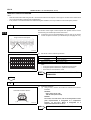
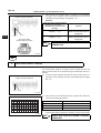
BASIC INSPECTION
HINT:
If the malfunction cannot be determined by troubleshooting, the problem
area can be narrowed down by performing the following basic inspection.
1.
CHECK BATTERY VOLTAGE
(a) Check the condition of the battery.(See page CH - 3.)
2.
CHECK WHETHER ENGINE CRANKS
(a) Make sure that the engine cranks.
HINT:
If the engine does not crank, check the starting systems.
3.
CHECK WHETHER ENGINE STARTS
(a) Make sure that the engine starts.
HINT:
If the engine does not start, check fuel pressure and spark.
4.
CHECK AIR FILTER
(a) Check the air filter.
HINT:
If the air filter is dirty, clean or replace it.
5.
CHECK ENGINE IDLE SPEED (See page EM - 2)
6.
CHECK IGNITION TIMING (See page EM - 1)
7.
CHECK FUEL PRESSURE (See page FU - 3)
8.
CHECK FOR SPARK (See page IG - 1)
9.
CHECK COMPRESSION (See page EM - 2)
ES
ES–2
ENGINE CONTROL - EFI SYSTEM (3SZ-VE, K3-VE)
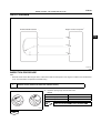
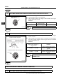
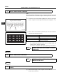
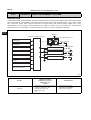
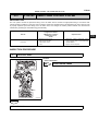
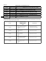
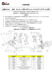
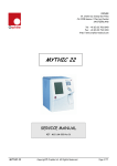
LOCATION
ENGINE ROOM R/B
EFI FUSE
INSTRUMENT PANEL J/B
FAN RELAY
ES
ST RELAY
E/G FUSE
EFI RELAY
F/P RELAY
AM2 FUSE
DLC
THROTTLE BODY ASSEMBLY
THROTTLE POSITION SENSOR
ISCV
COMBINATION METER
VACUUM SENSOR
CAMSHAFT POSITION SENSOR
EVAP PURGE VSV
INLET AIR TEMPERATURE
SENSOR
FUEL INJECTOR ASSEMBLY
FUEL PUMP
AUTOMATIC CONTROL
COMPUTER
ENGINE CONTROL COMPUTER
OXYGEN SENSOR NO. 2
KNOCK CONTROL SENSOR
COOLANT TEMPERATURE
IGNITION COIL ASSEMBLY
OXYGEN SENSOR
CRANKSHAFT POSITION SENSOR
CAMSHAFT TIMING OIL CONTROL VALVE ASSEMBLY
A135187J02
ES–3
ENGINE CONTROL - EFI SYSTEM (3SZ-VE, K3-VE)
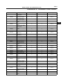
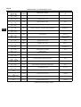
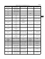
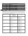
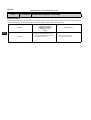
DIAGNOSTIC TROUBLE CODE CHART
DTC No.
Diagnostic Item
Lamp
Code Memory
See Page
P0105/31
Air intake pressure sensor
signal system
{
{
ES - 28
P0110/43
Intake air temperature
sensor signal system
{
{
ES - 31
P0115/42
Coolant temperature
sensor signal system
{
{
ES - 35
P0120/41
Throttle sensor signal
system
{
{
ES - 38
P0130/21
Front O2 sensor signal
system
{
{
ES - 43
P0135/23
Front O2 sensor heater
signal system
{
{
ES - 47
P0136/22
Rear O2 sensor signal
system
{
{
ES - 50
P0141/24
Rear O2 sensor heater
{
{
ES - 47
P0171/25
Fuel system (lean
malfunction)
{
{
ES - 53
P0172/26
Fuel system (rich
malfunction)
{
{
ES - 53
P0300/17
Misfire
{
{
ES - 58
P0301/17
Misfire (#1 cylinder)
{
{
ES - 58
P0302/17
Misfire (#2 cylinder)
{
{
ES - 58
P0303/17
Misfire (#3 cylinder)
{
{
ES - 58
P0304/17
Misfire (#4 cylinder)
{
{
ES - 58
P0325/18
Knock sensor signal
system
×
{
ES - 63
P0335/13
Engine revolution sensor
signal system
{
{
ES - 66
P0340/14
Cam angle sensor signal
system
{
{
ES - 69
P0350/16
Ignition primary system
{
{
ES - 72
P0443/76
EVAP purge VSV
{
{
ES - 79
P0420/27
Catalyst deterioration
{
{
ES - 75
P0500/52
Vehicle speed signal
system
{
{
ES - 81
P0505/71
ISC valve system
{
{
ES - 83
P0535/44
A/C evaporator
temperature sensor signal
system
×
{
ES - 87
P1105/32
Atmospheric pressure
sensor signal system
{
{
ES - 89
P1300/36
Ionic current system
{
{
ES - 90
P1346/75
VVT control system (valve
timing fail)
{
{
ES - 94
P1349/73
VVT control (advance
angle and retard angle fail)
{
{
ES - 95
P1351/62
Timing chain control
system
×
{
ES - 99
P1510/54
Starter signal system
{
{
ES - 100
P1560/61
Short to back up power
source
{
{
ES - 103
ES
ES–4
ENGINE CONTROL - EFI SYSTEM (3SZ-VE, K3-VE)
DTC No.
ES
Lamp
Code Memory
See Page
P1600/83
Keyless system/
immobiliser system
communication system
(malfunction in ECU)
Diagnostic Item
×
{
ES - 105
P1601/81
Keyless / immobiliser
system communication
system (code does not
match, communication
error)
×
{
ES - 106
P1656/74
OCV control system
{
{
ES - 109
U0101/82
EAT/ CVT communication
(reception)
{
{
ES - 112
U0121/86
ABS communication
(reception)
{
{
ES - 112
U0156/87
Meter communication
(receiving)
{
{
ES - 112
U1000/85
EAT communication
(transmission)
{
{
ES - 112
U1002/88
CAN communication
{
{
ES - 112
PROBLEM SYMPTOMS TABLE
Symptom
Engine does not crank
Suspected Area
1. Starter assembly
ST - 10
2. Starter relay
ST - 21
3. Neutral start switch system
AT - 57
1. See flowchart (ECU power source)
2. Igniter system
No initial combustion (engine does not start)
Engine does not start (when cold)
IG - 1
ES - 115
4. Injector
FU - 12
1. See flowchart (fuel pump control system)
Engine does not start but cranks normally)
ES - 120
3. See flowchart (fuel pump control system)
5. Crank position sensor system
Incomplete combustion (engine does not start)
See Page
2. Igniter system
IG - 14
ES - 115
IG - 1
3. Injector
FU - 12
4. Crank position sensor system
IG - 14
1. Throttle body system
ES - 129
2. See flowchart (fuel pump control system)
ES - 115
3. Igniter system
IG - 1
4. Spark plug
IG - 18
5. Compression
EM - 2
6. Injector
FU - 12
7. Crank position sensor system
IG - 14
1. Throttle body system
ES - 129
2. See flowchart (fuel pump control system)
ES - 115
3. Injector
FU - 12
4. Igniter system
IG - 1
5. Spark plug
IG - 18
6. Crank position sensor system
IG - 14
ES–5
ENGINE CONTROL - EFI SYSTEM (3SZ-VE, K3-VE)
Symptom
Engine does not start (when warm)
Fast idle problem
Idle speed is too high
Suspected Area
ES - 129
2. See flowchart (fuel pump control system)
ES - 115
3. Injector
FU - 12
4. Igniter system
IG - 18
6. Crank position sensor system
IG - 14
1. Throttle body system
2. Spark plug
2. See flowchart (ECU power source)
ES - 120
2. Neutral start switch system
3. See flowchart (fuel pump control system)
Surging
Engine stall (right after starting engine)
Engine stall (right after slowing down)
AT - 57
ES - 115
FU - 12
ES - 129
2. Injector
FU - 12
3. Igniter system
IG - 1
4. Compression
EM - 2
ES - 115
IG - 18
1. Throttle body system
ES - 129
2. See flowchart (ECU power source)
ES - 120
3. See flowchart (fuel pump control system)
ES - 115
IG - 17
1. See flowchart (fuel pump control system)
ES - 115
2. Injector
FU - 12
3. Igniter system
IG - 1
4. Spark plug
IG - 17
1. Igniter system
IG - 1
2. Injector
FU - 12
1. See flowchart (fuel pump control system)
ES - 115
2. Spark plug
IG - 17
3. Injector
FU - 12
1. See flowchart (fuel pump control system)
ES - 115
2. Throttle body system
ES - 129
3. Crank position sensor system
IG - 14
4. Igniter system
IG - 1
1. Injector
FU - 12
2. Throttle body system
ES - 129
3. Engine control computer
ES - 16
4. Crank position sensor system
IG - 14
5. Igniter system
1. Neutral start switch system
Engine stall (when the shift lever is in the D position)
ES - 129
1. Throttle body system
4. Spark plug
After fire
AT - 57
4. Injector
6. Spark plug
Stumbling, poor acceleration
IG - 18
ES - 129
5. See flowchart (fuel pump control system)
Hunting
ES - 129
1. Throttle body system
1. Throttle body system
Idle is unstable
IG - 1
5. Spark plug
3. Neutral start switch system
Idle speed is too low
See Page
1. Throttle body system
2. Throttle body system
IG - 1
AT - 57
ES - 129
3. Crank position sensor system
IG - 14
4. Igniter system
IG - 1
ES
ES–6
ENGINE CONTROL - EFI SYSTEM (3SZ-VE, K3-VE)
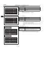
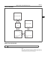
HOW TO PROCEED WITH
TROUBLESHOOTING
ES
1
VEHICLE BROUGHT TO WORKSHOP
2
CONDUCT CUSTOMER PROBLEM ANALYSIS AND CHECK SYMPTOMS (See page ES - 7.)
3
CHECK CAN COMMUNICATION SYSTEM (See page CA - 4.)
(a)
Using the DS-II, select CAN BUS DIAGNOSIS / CHECK ECU
CONNECTED TO CAN BUS LINE screen (see CA - 8), and make
sure all ECU and sensors that are connected to the CAN
communication are displayed on the screen.
NG
GO TO CAN COMMUNICATION SECTION
OK
4
CHECK FOR DIAGNOSTIC TROUBLE CODES (See page ES - 8.)
(a)
(b)
(c)
Check for DTCs and freeze frame data.
Delete DTCs and freeze frame data.
Recheck for DTCs.
(1) If DTCs are present, go to A.
(2) If DTCs are not present, go to B.
B
GO TO STEP 7
A
5
TROUBLESHOOT USING DTCS OR DIAGNOSTIC TROUBLE CODE CHART (MAIN SUSPECTED
AREAS)
(a)
(b)
6
If the location of the problem is determined, go to A.
If the location of the problem is not determined, go to B.
A
GO TO STEP 12
B
GO TO STEP 9
PROBLEM SYMPTOMS TABLE (See page ES - 4.)
(a)
(b)
If the location of the problem is determined, go to A.
If the location of the problem is not determined, go to B.
ES–7
ENGINE CONTROL - EFI SYSTEM (3SZ-VE, K3-VE)
A
GO TO STEP 12
B
7
BASIC INSPECTION (See page ES - 1.)
(a)
(b)
A
If the location of the problem is determined, go to A.
If the location of the problem is not determined, go to B.
GO TO STEP 12
ES
B
8
CHECK USING DS-II (See page ES - 21.)
(a)
(b)
(c)
A
Select ECU data list or active test.
If the location of the problem is determined, go to A.
If the location of the problem is not determined, go to B.
GO TO STEP 12
B
9
CHECK VOLTAGE OF ECU VOLTAGE AND CIRCUIT (See page ES - 16.)
10
REPAIR PROBLEM AREAS
11
CHECK FOR DIAGNOSTIC TROUBLE CODES (See page ES - 8.)
END
CUSTOMER PROBLEM
CHECK SHEET
1.
ANALYSIS
Ask the customer about problems and concerns.
(a) Follow the previous troubleshooting procedure, and use the
customer problem analysis check sheet to make sure that the
proper questions are asked when interviewing the customer
about problems.
ES–8
ENGINE CONTROL - EFI SYSTEM (3SZ-VE, K3-VE)
Engine Problem Diagnosis Check Sheet
Model
Date vehicle brought in
Date registered
VIN
Service history
Registration No.
Odometer reading
Date problem first occurred
No/Yes (__times)
km
Accessories
Main region/purpose of travel
Previous vehicle
ES
Customer profile/characteristics
Description of symptoms
Off/On (
Warning light illumination
System Conditions
Driving
Conditions
Road Conditions
Starting off
Cruising
Increasing
speed
Decreasing
speed
Braking
Turning
Stopped
Not related
Others
(
)
Speed problem first
occurred( )km/h
Shift position ( ) range
Starting off
Immediately after
start off
( ) min after start
Check
After ( )min driving
Results
Cold
Warm
Idling
Others (
)
Level
Uphill
Downhill
Dry paved road
Wet paved road
Unpaved/rough
road
Snowy/icy road
Uneven,
manholes etc.
Others (
)
)
Problem
Frequency
Others
Accelerator
opening
( )%
Ambient air
temperature
( )
Always
One time only
Sometimes
(_)times a day
(_)times a week
(_)times a month
Weather
( )
Additional Items
DTC Inspection
Malfunction Indicator
Lamp (MIL) Off/On
Normal Code(s)
Malfunction code(s)(all noted)
Fuel pressure when
engine stopped
Fuel pressure 1 min.
after engine stopped
Problem details
Inspection Driving conditions and location when problem first
Results
occurred and reoccurred
Reoccurrence conditions
Occasional
Always
Dealer Name
Once problem occurs, it continues
Office
Person in charge
Does not reoccur
Technician
A066666
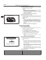
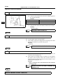
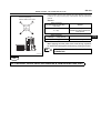
CHECK / CLEAR DTCs
1.
PREPARE FOR INSPECTION
(a) Make sure that the throttle valve is fully closed.
ENGINE CONTROL - EFI SYSTEM (3SZ-VE, K3-VE)
(b)
(c)
2.
DS
DLC
ES–9
Move the shift lever to the N or P position.
Turn off the air conditioner.
CHECK DTCs (using DS-II)
(a) Connect the DS-II to the DLC.
(b) Turn the ignition switch to the ON position.
(c) Turn the DS-II power ON.
(d) Following the prompts on the screen, select CHECK DTCs/
FREEZE FRAME DATA on the DIAGNOSIS - EFI screen, and
check for DTCs.
HINT:
If a DTC is displayed on the DS-II, see IN - 30.
A136722J02
3.
EFIT
E
G100942
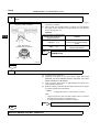
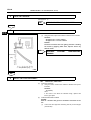
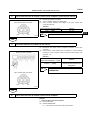
CHECK DTCs (using the check engine warning light)
NOTICE:
• Turn the ignition switch to the ON position before reading the
DTCs, and check that the check engine warning light is
flashing.
• The CHECK MODE cannot be used.
(a) Turn the ignition switch off.
(b) Using the diagnosis check wire, short terminals 12 (EFIT) and 4
(E) of the DLC.
SST
09843-18020
NOTICE:
• Do not connect the diagnosis check wire to the wrong
terminals. Doing so may cause malfunctions.
• Use only the dedicated diagnosis check wire.
(c)
Normal Code
0.25 Sec.
0.25 Sec.
2 Sec.
Abnormal Code (Example [11] [23] )
Repeated
4 Sec. 1.5 Sec.
2.5 Sec.
0.5 Sec. 0.5 Sec.
C040092J07
(d)
4.
Turn the ignition switch to the ON position, and count the
number of flashes of the check engine warning light.
HINT:
• If the indicator light does not indicate a DTC (the light does
not blink), there may be a malfunction in the TC terminal, VC
terminal, or the computer.
• If the check engine warning light remains on, the wire
harness may have a short circuit (due to being pinched or
for other reasons) or the computer may be malfunctioning.
• If an irrelevant DTC is detected, the computer may be
malfunctioning.
• If the check engine warning light comes on at engine speed
of approximately1000 r/min or more and no DTC is output,
turn the ignition switch to the OFF position and recheck.
Disconnect diagnosis check wire No.2.
CHECK FREEZE DATA (using DS-II)
(a) Using the DS-II, follow the prompts on the screen, and select
the DTC that records the freeze data (marked !) from the DTC /
FREEZE DATA screen.
HINT:
• The engine condition (ECU data) before and after DTCs are
detected can be checked using the time series freeze frame
data. (See page ES - 10.)
• The time series freeze frame data is helpful in
troubleshooting when the symptom cannot be reproduced.
ES
ES–10
ES
ENGINE CONTROL - EFI SYSTEM (3SZ-VE, K3-VE)
5.
DELETE RECORDED DTCs (using DS-II)
(a) Following the prompts on the screen, select the DTC / FREEZE
DATA screen and delete the DTCs.
NOTICE:
• If the DTCs cannot be deleted, turn the ignition switch
off, then perform the procedure again.
• Until the cause of problems are clarified, do not delete
the DTCs using the DS-II.
• Write the DTCs down before deleting them.
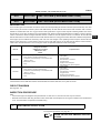
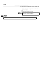
6.
DELETE DTCs (by removing a fuse)
(a) The recorded codes can be deleted by removing the EFI fuse
(15A) for more than 60 seconds after turning the ignition switch
to the OFF position.
NOTICE:
• Be sure to clear the DTCs and check that a normal code
is output after the EFI system inspection is finished.
• Do not delete the DTCs by clearing the battery
(removing a fuse) until the cause of the problems is
clarified.
• Write the DTCs down before deleting them.
Engine Room R/B
EFI Fuse
A133909J01
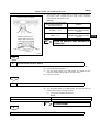
Freeze Frame Data
1.
CHECK FREEZE FRAME DATA
(a) If the symptom can not be reproduced even though a DTC is
detected, check the freeze frame data.
(1) Connect the DS-II to the DLC.
(2) Turn the ignition switch to the ON position.
(3) Select DIAGNOSIS → EFI → DTC / FREEZE DATA.
(4) Detected DTCs will be displayed on the DTC screen.
(5) Select the DTCs to check the desired freeze data.
HINT:
The DTCs are marked with the character, !, and the
highlighted codes contain freeze data.
2.
CHECK TIME SERIES FREEZE FRAME DATA
(a) Select the item to check the desired time series freeze data on
the freeze data screen.
HINT:
• The previous version of freeze data recorded ECU data only
when DTCs occurred (when detected), but time series
freeze frame data also records ECU data before and after
DTCs are detected.
• Time series freeze frame data can be checked when TIME
SERIES FREEZE DATA CAN BE CHECKED is displayed
on the freeze data screen.
• The time series freeze frame data can display up to 3 data
points, including the DTC inspection point, 1 point for before
inspection, and 1 point after inspection.
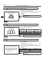
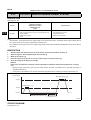
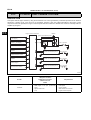
3.
FREEZE DATA CHART
Time Sequence Of Data Recording Timing
DTC Detection Point
▼
1
2
3
:Time Sequence of Data Recording Point
(Recorded At 0.5 Second Intervals)
A138074J01
Item
Shorted Item
Coolant temperature
ECT
Air intake pressure
MAP
Engine speed
r/min
ES–11
ENGINE CONTROL - EFI SYSTEM (3SZ-VE, K3-VE)
Item
Shorted Item
Vehicle speed
VS
Ignition timing advance angle
ITA
Injection volume
TAUX
Injection timing
TAUZ
ES
ES–12
ENGINE CONTROL - EFI SYSTEM (3SZ-VE, K3-VE)
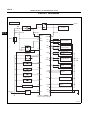
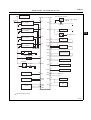
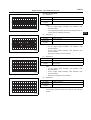
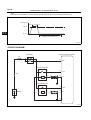
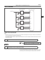
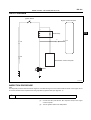
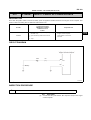
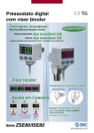
CIRCUIT DIAGRAM
General Export
Starter
AM2
A/T ECU
ST Relay
Ignition Switch
ES
MAIN
E/G 10A
EFI 15A
120
38
Battery
39
ST 7.5A
IGSW
STSW
BAT
N1+
MRO
EFI Relay
N1-
N2+
N227
59
1
128
2
58
1
127
2
121
2
123
2
15
1
Oxygen Sensor
3
18
1
Oxygen Sensor
NO. 2
2
56
1
53
3
Crankshaft
Position Sensor
Camshaft
Position Sensor
+B
KNK
F/P Relay
35
107
Knock Control
Sensor
1
FC1
To Fuel Pump
OX1
OXH1
4
To +B
Injector No. 1
1
2
24
#10
OX2
Injector No. 2
2
1
23
#20
VC
Injector No. 3
VTH
2
1
22
THW
2
2
EVAP Purge VSV
1
21
16
THA
PRG
2
Indicator E1
3
ISCV
65
54
2
55
1
Coolant Temperature
1
#40
E2
1
2
#30
Injector No. 4
1
Throttle Position
Sensor
E01
ISC
E1
Inlet Air Temperature
Sensor
2
19
20
125
Engine Control Computer
A135479J01
ES–13
ENGINE CONTROL - EFI SYSTEM (3SZ-VE, K3-VE)
General Export
To IG2
Stop Light Switch Assembly
3
1
4
63
STP 10A
IG1
Ignition Coil Assembly
(No. 1 Cylinder)
STP
To Battery
43
Stop Light
3
1
4
62
IG2
Ignition Coil Assembly
(No. 2 Cylinder)
DEF
11
Defogger
ES
Defogger Switch
To DEF Fuse
3
1
4
61
IG3
Ignition Coil Assembly
(No. 3 Cylinder)
OCV+
1
4
3
OCV-
60
26
1
OCV
2
25
IG4
Ignition Coil Assembly
(No. 4 Cylinder)
VCPM
PIM
To Ignition Plugs
E2PM
ACEV
E21
Engine Check Light
57
52
3
2
Vacuum Sensor
1
122
45
1 A/C Evaporator
Temperautre Sensor
2
116
13
W
EPS
12
P/S Oil Pressure Switch
FAN Relay
37
Fan Motor
FAN1
SIO2
FPOF
Alternator
135
ALT
BLW
ACSW
9
Meter ECU
8
7
A/T ECU
6
4
HCAN
REV
117
44
9
Immobiliser ECU*
Airbag ECU
42
45
To A/C
118
Tachometer
LCAN
CANH
EFIT
113
DLC
CANL
ATNE
Engine Control Computer
: Immobiliser Equipped Vehicles
A135480J01
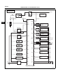
ES–14
ENGINE CONTROL - EFI SYSTEM (3SZ-VE, K3-VE)
EU Specifications
Starter
AM2
A/T ECU
ST Relay
Ignition Switch
MAIN
E/G 10A
EFI15A
120
ES
38
Battery
39
ST 7.5A
IGSW
STSW
BAT
N1+
MRO
EFI Relay
N1-
N2+
N227
59
1
128
2
58
1
Crankshaft Position
Sensor
127
Camshaft Position
2 Sensor
121
2
123
2
15
1
18
2
14
1
+B
KNK
F/P Relay
34
107
Knock Control
Sensor
1
FAN2
To Fuel Pump
OX1
OXH1
4
Oxygen Sensor
3
To B
Injector No. 1
1
24
2
#10
OX2
OXH2
Injector No. 2
2
1
23
VC
22
2
VTH
2
THW
2
EVAP Control VSV
21
1
16
THA
PRG
2
To E1
3
ISCV
65
To B
56
1
53
3
54
2
55
1 Intake Air Temperature 2
Sensor
Throttle Position
Sensor
2
Coolant Temperature
Sensor
1
#40
E2
1
3
#30
Injector No. 4
1
4
#20
Injector No. 3
1
Oxygen Sensor
NO. 2
E01
ISC
E1
19
20
125
Engine Control Computer
A138429J01
ES–15
ENGINE CONTROL - EFI SYSTEM (3SZ-VE, K3-VE)
EU Specifications
Stop Light Switch Assembly
To IG2
1
Ignition Coil Assembly
4 (No. 1 Cylinder)
3
63
2
51
To Battery
IG1
ICMB1
STP 10A
43
STP
Stop Light
1
3
62
Ignition Coil Assembly
4 (No. 2 Cylinder)
2
50
IG2
11
DEF
Defogger
ICMB2
ES
Defogger Switch
To DEF Fuse
1
3
61
Ignition Coil Assembly
4 (No. 3 Cylinder)
2
49
IG3
ICMB3
26
OCV+
1
3
61
Ignition Coil Assembly
4 (No. 4 Cylinder)
2
48
1
OCV
2
25
OCVIG4
ICMB4
VCPM
To Ignition Plugs
45
ACEV
Engine Check Light
3
Intake Air
2
Pressure Sensor
1
122
E2PM
Condensor
57
52
PIM
1 A/C Evaporator
Temperature Sensor
2
116
E21
13
W
12
PST
P/S Oil Pressure Switch
Fan Relay
37
Fan Motor
FAN1
117
SIO2
44
FPOF
Alternator
135
ALT
9
8
7
A/T ECU
6
4
HCAN
Immobiliser ECU
Airbag ECU
42
BLW
ACSW
Meter ECU
9
REV
45
To A/C
118
Tachometer
113
DLC
LCAN
CANH
EFIT
CANL
ATNE
A/T
*
To Deicer
Engine Control Computer
* : Specifications For Cold Region Vehicles
A138430J01
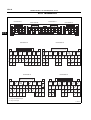
ES–16
ENGINE CONTROL - EFI SYSTEM (3SZ-VE, K3-VE)
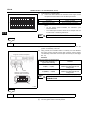
ECU TERMINALS
Connector A
27
26
25
24
23
22
20
21
69 68 67 66 65 64 63 62 61 60
ES
Connector C
Connector B
19
18
17
16
15
14
59 58 57 56 55 54 53 52 51 50 49 48
13
12
11
10
Connector D
9
7
8
47 46 45 44 43 42 41 40 39 38
6
5
4
3
2
1
37 36 35 34 33 32 31 30 29 28
106105 104103102101100 99 98 97
96 95
94 93
92 91 90 89
88 87 86 85 84 83 82 81 80 79 78
77 76
75 74 73 72 71 70
135134
128127
126125
124123 122 121
120119 118 117 116
112 111
110109
133132 131130129
115 114 113
108107
Connector B
Connector A
*2
+B
OCV+
OCV-
#10
#20
#30
E01
#40
E2
OX2
PRG
OXH1
*2
ISC
IG1
IG2
IG3
IG4
ALT ALTC
N1+ N2+ VCPM VC
N1-
THA THW VTH PIM ICM
B1
Connector C
W
DEF
IGSW
REV SIO2 E21
*2
Connector D
HCAN
LCAN
CANH
CANL
ATNE
*1
ACEV FPOF STP BLW
*2
ICM ICM ICM
B2 B3 B4
PST OX1 E2PM KNK
E1
N2-
*2
OXH2
A/T MRO BAT
ACSW
*2
FAN1 MGC FC1 FAN2
EFIT
STSW
*1 : Only For General Export
*2 : Only For Europe
A139505J01
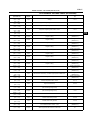
ES–17
ENGINE CONTROL - EFI SYSTEM (3SZ-VE, K3-VE)
ECU TERMINAL VOLTAGE CHART (EFI SYSTEM)
Terminal Name
(Terminal No.)
Input /
Output
Measurement condition
Standard
(V)
BAT ←→ E1
(38←→125)
Input
Always
10-14
+B ←→ E1
(27←→125)
Input
Engine is stopped, ignition switch is ON
10-14
IGSW ←→ E1
(120←→125)
Input
Engine is stopped, ignition switch is ON
10-14
MRO ←→ E1
(39←→125)
Input
Engine is stopped, ignition switch is ON
10-14
VC ←→ E2
(56←→19)
Input
Engine is stopped, ignition switch is ON
4.5-5.5
IG1 ←→ E1
(63←→125)
Output
Engine is idling
Pulse is generated
(Waveform 1)
IG2 ←→ E1
(62←→125)
Output
Engine is idling
Pulse is generated
(Waveform 1)
IG3 ←→ E1
(61←→125)
Output
Engine is idling
Pulse is generated
(Waveform 1)
IG4 ←→ E1
(60←→125)
Output
Engine is idling
Pulse is generated
(Waveform 1)
N1+ ←→ N1(59←→128)
Input
Engine is idling
Pulse is generated
(Waveform 2)
N2+ ←→ N2(58 ←→ 127)
Input
Engine is idling
Pulse is generated
(Waveform 3)
# 10 ←→ E1
(24←→125)
Output
Engine is idling
Pulse is generated
(Waveform 4)
# 20 ←→ E1
(23←→125)
Output
Engine is idling
Pulse is generated
(Waveform 4)
# 30 ←→ E1
(22←→125)
Output
Engine is idling
Pulse is generated
(Waveform 4)
# 40 ←→ E1
(21←→125)
Output
Engine is idling
Pulse is generated
(Waveform 4)
OX1 ←→ E2
(123←→19)
Input
O2 sensor is warmed up, constant engine speed of 3000 r/min
Pulse is generated
(Waveform 5)
OX2 ←→ E2
(18←→19)
Input
O2 sensor is warmed up, constant engine speed of 3000 r/min
Pulse is generated
(Waveform 5)
KNK ←→ E2
(121←→19)
Input
Engine is idling
Pulse is generated
(Waveform 6)
THW ←→ E2
(54←→19)
Input
Coolant temperature 60 to 120°C
0.3-1.3
THA ←→ E2
(55←→19)
Input
Engine is warmed up
0.5-4.3
W ←→ E1
(13←→125)
Output
Engine is idling
(the check engine light is off)
10-14
W ←→ E1
(13←→125)
Output
Disconnect the connector of the coolant temperature sensor.
(the check engine light is on)
0-3.5
STSW ←→ E1
(107←→125)
Input
Starter switch is ON
10-14
VTH ←→ E2
(53←→19)
Input
Throttle valve is fully closed
0.4-0.8
VTH ←→ E2
(53←→19)
Input
Throttle valve is fully opened
3.2-5.0
ISC ←→ E1
(65←→125)
Output
Engine is idling
Air conditioner switch is OFF → ON
Pulse is generated
(Waveform 7)
OXH1 ←→ E1
(15←→125)
Output
After engine idles for more than 5 seconds
0-1
ES
ES–18
ES
ENGINE CONTROL - EFI SYSTEM (3SZ-VE, K3-VE)
Terminal Name
(Terminal No.)
Input /
Output
Measurement condition
Standard
(V)
OXH1 ←→ E1
(15←→125)
Output
Engine is stopped, ignition switch is ON
10-14
STP ←→ E1
(43←→125)
Input
Stop light switch is ON
10-14
STP ←→ E1
(43←→125)
Input
Stop light switch is OFF
0-0.5
PRG ←→ E1
(16←→125)
Output
Engine is stopped, ignition switch is ON
10-14
PRG ←→ E1
(16←→125)
Output
Engine is warmed up, accelerator pedal is depressed
Pulse is generated
(Waveform 8)
FC1 ←→ E1
(35←→125)
Output
Engine is stopped, ignition switch is ON
10-14
FC1* ←→ E1
(35←→125)
Output
Engine is idling
Below 1.2
REV ←→ E1
(118←→125)
Output
Engine is idling
Pulse is generated
(Waveform 9)
FAN1 ←→ E1
(37←→125)
Output
Magnetic clutch is OFF
10-14
FAN1 ←→ E1
(37←→125)
Output
Magnetic clutch is ON
Below 1
OCV+ ←→ OCV(26←→25)
Output
Engine is stopped, ignition switch is ON
Pulse is generated
(Waveform 10)
EPS ←→ E1
(12←→125)
Input
Engine is idling
Steering wheel is centered
10-14
EPS ←→ E1
(12←→125)
Input
Engine is idling
Steering wheel is turned
0-1
ALTC ←→ E1
(134←→125)
Input
Engine is stopped, ignition switch is ON
10-14
ALT ←→ E1
(135←→125)
Input
Engine is stopped, ignition switch is ON
10-14
VCPM ←→ E2PM
(57←→122)
Input
Engine is stopped, ignition switch is ON
4.5-5.5
PIM ←→ E2PM
(52←→122)
Input
Sensor adjusted to stable ambient temperature
3.1-4.1
ACEV ←→ E21
(45←→116)
Input
Air conditioning is ON
0.15-4.8
E1 ←→ Body ground
(125)
Ground
Always (continuity check)
Continuity
E2 ←→ Body ground
(19)
Ground
Always (continuity check)
Continuity
E01 ←→ Body ground
(20)
Ground
Always (continuity check)
Continuity
E21 ←→ Body ground
(116)
Ground
Always (continuity check)
Continuity
*: FAN2 terminal for European models
ENGINE CONTROL - EFI SYSTEM (3SZ-VE, K3-VE)
1.
ES–19
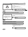
Oscilloscope waveform
(a) Waveform 1
Tester Connection
Tool setting
Measurement
condition
IG1, IG2, IG3, IG4 ←→ E1
5 V/DIV, 10 ms/DIV
Engine is idling after warming up
HINT:
• As the engine speed increases, the waveform cycle
becomes shorter.
• The oscilloscope waveform shown as an example, does not
include noise or chattering waveforms.
A134282
(b)
Waveform 2
Tester Connection
Tool setting
Measurement
condition
N1+ ←→ N12 V/DIV, 20 ms/DIV
Engine is idling
HINT:
• As the engine speed increases, the waveform cycle
becomes shorter.
• As the engine speed increases, each waveform cycle
becomes shorter.
• Noise may cause DTCs to be recorded.
A134283
(c)
Waveform 3
Tester Connection
Tool setting
Measurement
condition
N2+ ←→ N22 V/DIV, 20 ms/DIV
Engine is idling
HINT:
• As the engine speed increases, the waveform cycle
becomes shorter.
• As the engine speed increases, each waveform cycle
becomes shorter.
• Noise may cause DTCs to be recorded.
A134284
(d)
Waveform 4
Tester Connection
Tool setting
Measurement
condition
# 10, # 20, # 30, # 40 ←→ E1
20 V/DIV, 20 ms/DIV
Engine is idling
HINT:
As the engine speed increases, the waveform cycle becomes
shorter.
A134285
ES
ES–20
ENGINE CONTROL - EFI SYSTEM (3SZ-VE, K3-VE)
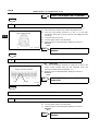
(e)
Waveform 5
Tester Connection
Tool setting
Measurement
condition
OX1, OX2 ←→ E1
0.2 V/DIV, 500 ms/DIV
Oxygen sensor is warmed up, constant engine speed of
3000 r/min
HINT:
Repeat between 0 (LEAN) ←→ 1(RICH)V
A134286
ES
(f)
Waveform 6
Tester Connection
Tool setting
Measurement
condition
1 V/DIV, 1 ms/DIV.
Engine is idling
HINT:
• The oscilloscope waveform shown as an example does not
include noise or chattering waveforms.
• The waveform amplitudes differ slightly depending on the
vehicle.
A134287
(g)
Waveform 7
Tester Connection
Air Conditioner OFF
KNK ←→ E1
Tool setting
Measurement
condition
ISC ←→ E1
5 V/DIV, 1 ms/DIV
Engine is idling, air conditioning is OFF → ON
HINT:
The duty ratio changes if the air conditioning is turned ON.
Air Conditioner ON
A134289
ES–21
ENGINE CONTROL - EFI SYSTEM (3SZ-VE, K3-VE)
(h)
Waveform 8
Tester Connection
Tool setting
Measurement
condition
PRG ←→ E1
5 V/DIV, 50 ms/DIV
Engine is idling
HINT:
If the waveform shown in the illustration is not indicated, idle the
engine for 10 minutes and recheck the waveform.
A134290
(i)
ES
Waveform 9
Tester Connection
Tool setting
Measurement
condition
REV ←→ E1
5 V/DIV, 10 ms/DIV
Engine is idling
HINT:
As the engine speed increases, the waveform cycle becomes
shorter.
A134291
(j)
Waveform 10
Tester Connection
OCV+ ←→ OCV-
Tool setting
5 V/DIV, 1 ms/DIV
Measurement
condition
Engine is idling
HINT:
As the engine speed increases, the waveform cycle becomes
shorter.
A134292
ECU DATA LIST / ACTIVE TEST
1.
ECU DATA LIST CHART
NOTICE:
• As the data list values may vary widely depending on slight
measurement errors, the measurement environment, or the
state of the vehicle due to wear and tear, it is very difficult to
indicate
specific
standard
values
(reference
values).Therefore, in some cases, an error may occur within
the range of reference values.
• For delicate symptoms such as stumbling, rough idle, obtain
and compare multiple test data using the same vehicle under
the same conditions, and determine problems wholistically
by considering all suspected items on the data list.
CARB SPECIFIED DATA CHART
Item
(Shorted Item)
MIL status
(MIL)
Item Description
•Illumination condition of
the check engine
warning light
•ON: on, OFF: off
Inspection Condition
Reference Value
Problem Area
Check engine warning light
is on → off
ON → OFF
W voltage
ES–22
Item
(Shorted Item)
ENGINE CONTROL - EFI SYSTEM (3SZ-VE, K3-VE)
Item Description
Inspection Condition
Reference Value
Problem Area
Number of power train
trouble codes
(DIAG)
•Indicates the number of
DTCs
•Displayed range: 0 to
255
-
0
-
Fuel system status of bank
1
(FS1)
•Fuel system status of
bank 1 is indicated
•OL (open loop):
conditions are not
satisfied to go from open
loop to closed loop
•CL (close loop): oxygen
sensor is used as
feedback for fuel control
•OL - Drive: open loop
due to drive condition
•OL - Fault: open loop
due to detected system
malfunction
•CL- Fault: close loop,
but at least one oxygen
sensor is malfunctioning.
Only one oxygen sensor
is used for fuel control
Engine is idling after
warming up
CL
OX1 Voltage
Fuel system status of bank
2
(FS2)
•Fuel system status of
bank 2 is indicated
•OL (open loop):
conditions are not
satisfied to go from open
loop to closed loop
•CL (close loop): oxygen
sensor is used as
feedback for fuel control
•OL - Drive: open loop
due to drive condition
•OL - Fault: open loop
due to detected system
malfunction
•CL- Fault: close loop,
but at least one oxygen
sensor is malfunctioning.
Only one oxygen sensor
is used for fuel control
-
-
-
O2 sensor position
(O2S11)
•Existence of bank 1
sensor 1 is indicated
•ON: yes, OFF: no
-
ON
-
O2 sensor position
(O2S12)
•Existence of bank 1
sensor 2 is indicated
•ON: yes, OFF: no
-
ON
-
O2 sensor position
(O2S13)
•Existence of bank 1
sensor 3 is indicated
•ON: yes, OFF: no
-
-
-
O2 sensor position
(O2S14)
•Existence of bank 1
sensor 4 is indicated
•ON: yes, OFF: no
-
-
-
O2 sensor position
(O2S21)
•Existence of bank 2
sensor 1 is indicated
•ON: yes, OFF: no
-
-
-
O2 sensor position
(O2S22)
•Existence of bank 2
sensor 2 is indicated
•ON: yes, OFF: no
-
-
-
ES
ES–23
ENGINE CONTROL - EFI SYSTEM (3SZ-VE, K3-VE)
Item
(Shorted Item)
Item Description
Inspection Condition
Reference Value
Problem Area
O2 sensor position
(O2S23)
•Existence of bank 2
sensor 3 is indicated
•ON: yes, OFF: no
-
-
-
O2 sensor position
(O2S24)
•Existence of bank 2
sensor 4 is indicated
•ON: yes, OFF: no
-
-
-
-
EOBD
-
OBD requirements
(OBD)
OBD requirements are
indicated (EOBD)
Calculated load value
(LOAD)
•Engine load amount is
indicated
•Displayed range: 0 to
100%
Engine is idling (air
conditioner is OFF, shift
lever is in N position)
0-5%
Air cleaner condition
Throttle valve condition
Calculated load value
(LOAD)
•Engine load amount is
indicated
•Displayed range: 0 to
100%
Engine speed is 2000 r/
min (air conditioning is
OFF, shift lever is in N
position)
5-7%
Air cleaner condition
Throttle valve condition
Coolant temperature
(ECT)
•Indicates engine coolant
temperature
•Displayed range: -40 to
140°C
Engine warmed up
completely
80 to 102°C
THW Voltage
Coolant temperature
(ECT)
•Indicates engine coolant
temperature
•Displayed range: -40 to
140°C
Short circuit in sensor
119 to 140°C
THW Voltage
Coolant temperature
(ECT)
•Indicates engine coolant
temperature
•Displayed range: -40 to
140°C
Short circuit in sensor
-40°C
THW voltage
Air intake pressure
(MAP)
•Air intake pressure is
indicated as absolute
pressure
•Displayed range: 0 to
120 kPa
Ignition switch is in ON
position, engine is stopped
70 to 104 kPa
•VCPM voltage
•PIM voltage
Air intake pressure
(MAP)
•Air intake pressure is
indicated as absolute
pressure
•Displayed range: 0 to
120 kPa
Engine is warmed up and
idling, air conditioner is
OFF
20 to 40 kPa
•VCPM voltage
•PIM voltage
Engine speed
(R/MIN)
Indicates the engine speed
Engine is stopped
(IG ON)
0 r/min
N voltage
Engine speed
(R/MIN)
Indicates the engine speed
Constant engine speed
No significant
fluctuation
N voltage
Vehicle speed
(VS)
Indicates vehicle speed
The vehicle is stopped
0 km/h
SPD voltage
Vehicle speed
(VS)
Indicates vehicle speed
Vehicle is running at
constant speed
No significant
fluctuation
SPD voltage
Ignition timing advance
angle
(ITA)
•Indicates ignition timing
of the 1-cylinder
•Displayed range: BTDC
63.5 to ATDC 64°
Engine is cranking (air
conditioner is OFF, shift
lever is in N position)
4-8°
IG voltage
Each sensor voltage
Ignition timing advance
angle
(ITA)
•Indicates ignition timing
of the No.1 cylinder
•Displayed range: BTDC
63.5 to ATDC 64°
Engine is idling (air
conditioner is OFF, shift
lever is in N position)
0-15°
IG voltage
Each sensor voltage
Ignition timing advance
angle
(ITA)
•Indicates ignition timing
of the No.1 cylinder
•Displayed range: BTDC
63.5 to ATDC 64°
Engine speed is 2000 r/
min (air conditioner is OFF,
shift lever is in N position)
20-40°
IG voltage
Each sensor voltage
ES
ES–24
Item
(Shorted Item)
ES
ENGINE CONTROL - EFI SYSTEM (3SZ-VE, K3-VE)
Item Description
Inspection Condition
Reference Value
Problem Area
Intake air temperature
(IAT)
•Indicates air
temperature
•Displayed range: -40 to
140°C
IG ON
Equivalent to ambient
temperature
THW voltage
Intake air temperature
(IAT)
•Indicates intake air
temperature
•Displayed range: -40 to
140°C
Short circuit in sensor
119 to 140°C
THW voltage
Intake air temperature
(IAT)
•Indicates intake air
temperature
•Displayed range: -40 to
140°C
Short circuit in sensor
-40°C
THW voltage
Opening angle of absolute
throttle sensor
(TP)
•Indicates opening angle
of throttle valve 1
•Displayed range: 0 to
100 %
Accelerator pedal fully
depressed
(IG ON)
10-24%
VC, VTH voltage
(Throttle position sensor
No.1)
Opening angle of absolute
throttle sensor
(TP)
•Indicates opening angle
of throttle valve 1
•Displayed range: 0 to
100 %
Accelerator pedal fully
released
(IG ON)
64-96%
VC, VTH voltage
(Throttle position sensor
No.1)
FrO2 sensor output
voltage
(O2FV)
•Indicates front O2
sensor output voltage
•Displayed range: 0 to
1.275 V
2500 r/min
Constant engine speed
0 to 1.0 V
OX1 voltage
FrO2 short-term fuel trim
(O2FP)
•Indicates front O2
sensor feedback trim
ratio
•Displayed range: -100
to 99.2%
2500 r/min
Constant engine speed
-20-20%
OX1 voltage
RrO2 sensor output
voltage
(O2RV)
•Indicates rear O2
sensor output voltage
•Displayed range: 0 to
1.275 V
2500 r/min
Constant engine speed
0.1 to 0.95 V
OX2 voltage
RrO2 short-term fuel trim
(O2RP)
•Indicates rear O2
sensor feedback trim
factor
•Displayed range: -100
to 99.2%
2500 r/min
Constant engine speed
10-70%
OX2 voltage
Driven distance at time of
malfunction
(DWM)
•Indicates distance
driven at time DTC is
recorded
•Displayed range: 0 to
65535 km
-
0 to 65535 km
-
Evaporation purge output
(EVAP)
•Indicates duty ratio of
evaporation purge VSV
output
•Displayed range: 0 to
100 %
Engine is idling after
warming up
0%
PRG voltage
Voltage of each sensor
Barometric pressure
(BARO)
•Indicates barometric
pressure
•Displayed range: 0 to
255 kPa
Ignition switch is in ON
position, engine is stopped
73 to 110 kPa
-
Power source voltage
(BAT)
•Indicates battery voltage
•Displayed range: 0 to 16
V
IG ON
11 to 14 V
BAT voltage
ES–25
ENGINE CONTROL - EFI SYSTEM (3SZ-VE, K3-VE)
DMC SPECIFIED DATA CHART
Item
(Shorted Item)
Electrical load
(DSW)
Air conditioner signal
[A/C]
Injection timing
(TAUZ)
Injection timing
(TAUZ)
Injection timing
(TAUZ)
Injection timing
(TAUZ)
ISC duty ratio
(ISCD)
Item Description
Indicates that there is
electrical load
Indicates that air conditioner is
operating
Actual displacement
angle
(VT)
Actual displacement
angle
(VT)
Target displacement
angle
(VTT)
Target displacement
angle
(VTT)
O2 sensor signal
(OX)
Light, defogger
OFF → ON
OFF → ON
Voltage of each switch
Air conditioner OFF → ON
OFF → ON
Voltage of each switch
Engine is cool when started
→ completely warmed up
1.4 to 2.5 msec
PIM, THW, OX1 voltage
•
•
Indicates injection timing
Displayed range: 0 to 200
msec
Engine warmed up and
idling (air conditioner is OFF,
shift lever is in N position)
1.4 to 1.8 msec
PIM, THW, OX1 voltage
•
•
Indicates injection timing
Displayed range: 0 to 200
msec
Engine speed is 2000 r/min
(air conditioner is OFF, shift
lever is in N position)
1.3 to 1.8 msec
PIM, THW, OX1 voltage
•
•
Indicates injection timing
Displayed range: 0 to 200
msec
Engine speed is 3000 r/min
(air conditioner is OFF, shift
lever is in N position)
1.0 to 1.5 msec
PIM, THW, OX1 voltage
•
Indicates duty ratio of ISC
drive signal
Displayed range: 0 to
100%
Engine warmed up and
idling (air conditioner is OFF,
shift lever is in N position)
6-14%
VC voltage
VTH voltage
THW voltage
Indicates duty ratio of ISC
drive signal
Displayed range: 0 to
100%
Engine warmed up and
idling (air conditioner is ON,
shift lever is in N position)
20-60%
VC voltage
VTH voltage
THW voltage
Indicates actual
displacement angle of
VVT
Displayed range: 0 to 50°
Engine is idling after
warming up
0-5°
OCV voltage
Indicates actual
displacement angle of
VVT
Displayed range: 0 to 50°
Engine is warmed up and
running at constant speed
0-10°
OCV voltage
Indicates target
displacement angle of
VVT control
Displayed range: 0 to 50°
Engine is idling after
warming up
0-5°
OCV voltage
Indicates target
displacement angle of
VVT control
Displayed range: 0 to 50°
Engine is warmed up and
running at constant speed
0-10°
OCV voltage
Indicates whether air-fuel
ratio measured by front
O2 sensor is lean or rich
2500 r/min
Constant engine speed
-
OX voltage
Indicates learned value of
air-fuel ratio
compensation
Displayed range: 0.75 to
1.25 V
2500 r/min
Constant engine speed
0.75 to 1.25 V
OX voltage
Indicates whether the idle
switch is ON or OFF (if the
vehicle does not have an
idle switch, the ON status
is when the throttle is
completely closed from
the open status)
Accelerator pedal fully
depressed → released
ON → OFF
VC voltage
VTH voltage
•
•
•
•
•
•
•
•
•
•
•
•
•
Idle signal
(IDL)
Problem Area
Indicates injection timing
Displayed range: 0 to 200
msec
•
VF monitor
(VF)
Reference Value
•
•
•
ISC duty ratio
(ISCD)
Inspection Condition
ES
ES–26
ENGINE CONTROL - EFI SYSTEM (3SZ-VE, K3-VE)
Item
(Shorted Item)
•
ISC learned value
(DLRN)
•
•
ES
Item Description
Inspection Condition
Reference Value
Problem Area
Indicates ISC learned
value
Displayed range: 0 to
100%
Engine warmed up and
idling (air conditioner is OFF,
shift lever is in N position)
6-14%
ISC voltage
Voltage of each sensor
Indicates ISC learned
value
Displayed range: 0 to
100%
Engine warmed up and
idling (air conditioner is ON,
shift lever is in N position)
6-14%
ISC voltage
Voltage of each sensor
ISC learned value
(DLRN)
•
Purge trim ratio
(FPG)
•
•
Indicates purge trim ratio
Displayed range: 0 to 0.5V
Engine is idling after
warming up
0
PRG voltage
Voltage of each sensor
Knocking trim advance
angle
(AKNK)
•
Indicates knock sensor
trim advance angle
Displayed range: 0 to 20°
Engine is idling after
warming up
0-3°
KNK voltage
Knocking trim advance
angle
(AKNK)
•
Indicates knock sensor
trim advance angle
Displayed range: 0 to 20°
4000 r/min
Constant engine speed
0-3°
KNK voltage
Indicates VVT angle
equivalency
Displayed range: 15 to 90°
Engine is warmed up and
idling
15-52°
VTH voltage
Indicates VVT angle
equivalency
Displayed range: 15 to 90°
3000 r/min
Constant engine speed
15-62°
VTH voltage
Indicates duty ratio of VVT
control
Displayed range: 0 to
100%
Engine is warmed up and
idling
20-50%
VTH voltage
Indicates duty ratio of VVT
control
Displayed range: 0 to
100%
3000 r/min
Constant engine speed
20-50%
VTH voltage
Indicates the actual air
intake pressure
Displayed range: 0 to 120
kPa
Engine is stopped
80 to 110 kPa
PIM voltage
Indicates the actual air
intake pressure
Displayed range: 0 to 120
kPa
Engine is warmed up and
idling
20 to 40 kPa
PIM voltage
Indicates the actual air
intake pressure
Displayed range: 0 to 120
kPa
2000 r/min
Constant engine speed
19 to 39 kPa
PIM voltage
TVVT angle equivalency
(VTB)
TVVT angle equivalency
(VTB)
•
•
•
•
•
•
•
Control duty ratio
(DVT)
•
•
Control duty ratio
(DVT)
Actual air intake
pressure
(PMVTB)
Actual air intake
pressure
(PMVTB)
Actual air intake
pressure
(PMVTB)
•
•
•
•
•
•
•
Stop lamp signal
(STP)
•
Indicates stop lamp signal
input
Brake pedal is released →
depressed
OFF → ON
STP voltage
Power steering signal
(PST)
•
Indicates power steering
signal input
Steering wheel is centered
→ turned
OFF → ON
EPS voltage
•
Indicates the number of
DTCs
Displayed range: 0 to 255
-
-
-
Number of DTCs
(DIAG)
•
ES–27
ENGINE CONTROL - EFI SYSTEM (3SZ-VE, K3-VE)
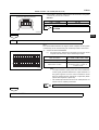
2.
Item
ACTIVE TEST
Condition
Constraint Condition
Fuel pump
Fuel pump is ON (active) / OFF (stopped)
-
Purge VSV
Purge control VSV is ON (current) / OFF (no
current)
-
All VSV for purge control are ON (current) / OFF
(no current)
-
T terminal is ON (short) / OFF (short released)
-
Radiator fan
Radiator fan is ON (active) / OFF (stopped)
-
ISC stepper
ISC active duty ratio setting (50 % open / 5 %
open)
All VSV
T terminal
Vehicle is stopped, engine is idling
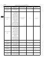
FAIL-SAFE CHART
If the codes shown below are recorded on the ECU, it will go to a fail-safe
mode.
Diagnostic Trouble Code
Fail-safe Operation
•
Fail-safe Mode Deactivation Condition
Vacuum sensor value is the pressure
estimated from the throttle opening angle
and the engine speed.If the signal from
the throttle position sensor is abnormal,
use the signal from the vacuum sensor as
the constant value.
If both the throttle opening angle and the
engine speed exceed the constant value,
decrease the fuel amount.
Return to normal condition
P0110/43
Use the signal from the intake air temperature
sensor as the constant value.
Return to normal condition
P0115/42
Use the signal from the coolant temperature
sensor as the constant value.
Return to normal condition
P0120/41
Use the signal from the throttle position
sensor as the constant value.
Return to normal condition
P0136/22
Set feedback control to open control.
Return to normal condition
P0325/18
Lag the ignition timing.
Return to normal condition
P0350/16
Stop the fuel injection to the cylinder that has
ignition signal problems.
Return to normal condition
P0535/44
Turn off the air conditioner.
Return to normal condition
P1600/83
P1601/81
Stop fuel injection and ignition.
Return to normal condition
P1656/74
Prohibit the oil control valve current control.
Return to normal condition
P0105/31
•
ES
ES–28
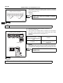
ENGINE CONTROL - EFI SYSTEM (3SZ-VE, K3-VE)
DTC
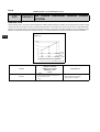
P0105/31
AIR INTAKE PRESSURE SENSOR SIGNAL
SYSTEM
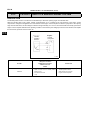
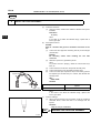
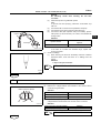
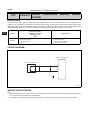
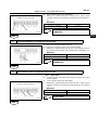
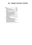
DESCRIPTION
Using a built-in sensor, the vacuum sensor detects the intake manifold pressure as voltage. At the same time, the engine control
computer determines the basic injection and ignition timing based on this voltage.The vacuum sensor does not detect barometric
pressure as a standard value, but it detects the absolute pressure of the inside of the intake manifold, so it is not effected by high
latitude or other barometric pressure changes.Therefore, a constant standard air-fuel ratio is maintained under all conditions.
ES
Voltage (V)
(3.96)
3.6
2.4
1.2
mmHg
150
450
750 (840)
20
60
100 (112)
kPa
Intake Manifold Internal Pressure
A051845J01
DTC Detection Condition
1.Diagnosis Condition
2.Malfunction Condition
3.Malfunction Time
4.Other
DTC No.
P0105/31
1.
2.
3.
4.
IG ON
Open or short to vacuum sensor circuit
0.5 seconds or more
1 trip
Suspected Area
•
•
•
Vacuum sensor
Wire harness and connector
Engine control computer
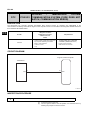
ES–29
ENGINE CONTROL - EFI SYSTEM (3SZ-VE, K3-VE)
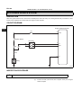
CIRCUIT DIAGRAM
Engine Control Computer
Vacuum Sensor
1
2
52
3
57
122
PIM
ES
VCPM
E2PM
A133545J02
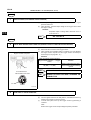
INSPECTION PROCEDURE
HINT:
Read the freeze frame data using the DS-II. Freeze data records aspects of the engine's condition when malfunctions occur. This
information is helpful when troubleshooting.
1
READ DS-II DATA (AIR INTAKE PRESSURE)
(a)
(b)
Connect the DS-II to the DLC.
Read the air intake pressure shown on the DS-II while the ignition
switch is turned to the ON position and the engine is stopped.
Result
Vehicle Condition
Standard
Engine is stopped, ignition switch is ON
80 to 110 kPa
Engine is warmed up and idling (air conditioner is OFF)
20 to 40 kPa
Engine is running at a constant speed of 2000 r/min (air
conditioner is OFF)
19 to 39 kPa
OK
NG
CHECK FOR INTERMITTENT PROBLEMS
ES–30
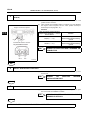
2
ENGINE CONTROL - EFI SYSTEM (3SZ-VE, K3-VE)
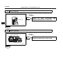
CHECK WIRE HARNESS AND CONNECTOR (ENGINE CONTROL COMPUTER VACUUM SENSOR)
(a)
(b)
Engine Control Computer
Disconnect the vacuum sensor connector and the engine control
computer connector B.
Using a tester, check whether there is continuity or a short between
the engine control computer and the vacuum sensor.(For terminal
layout, see page ES - 16.)
Standard
Inspection Terminal (Terminal Name)
Engine control computer ←→
Vacuum sensor
ES
57 (VCPM) ←→ 3 (VC)
VCPM
52 (PIM) ←→ 2 (PIM)
E2PM
PIM
122 (E2PM) ←→ 1 (E2)
Intake Pressure Sensor
Vehicle Side Connector
NG
E2
Standard
There is continuity and no shorts
between other terminals and body
ground
There is continuity, and no short
between other terminals
REPAIR OR REPLACE WIRE HARNESS OR
CONNECTOR
VC
PIM
A133546J01
OK
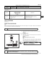
3
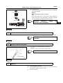
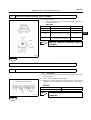
CHECK VACUUM SENSOR
(a)
(b)
Intake Pressure Sensor
Turn the ignition switch to the ON position.
Measure the voltage between the terminals of the vacuum sensor
connecter using the tester.
Standard
Inspection Terminal (Terminal Name)
1
2
3
(c)
E2
PIM
VC
A133547J01
CHECK AND REPLACE ENGINE ECU
3 (VC) ←→ 1 (E2)
4.5 to 5.5 V
2 (PIM) ←→ 1 (E2)
3.1 to 4.1 V
Remove the fuel pump relay and crank the engine, then measure the
voltage between the terminals of the vacuum sensor connector.
Standard
Inspection Terminal (Terminal Name)
Standard
2 (PIM) ←→ 1 (E2)
Voltage value fluctuates
OK
NG
Standard
REPLACE THE VACUUM SENSOR
ES–31
ENGINE CONTROL - EFI SYSTEM (3SZ-VE, K3-VE)
DTC
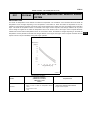
P0110/43
INTAKE AIR TEMPERATURE SENSOR SIGNAL
SYSTEM
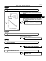
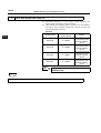
DESCRIPTION
The intake air temperature sensor detects the intake air temperature. The resistance of the thermistor built into intake air
temperature sensor changes depending on the temperature of the intake air. When the intake air temperature is low, the
resistance of the thermistor increases. Conversely, when the temperature of the intake air is high, the resistance of the thermistor
drops. The intake air temperature sensor is connected to the engine control computer, and, through resistance R, 5V power
source voltage is supplied to the intake air temperature sensor from terminal THA of the engine control computer. Because
resistance R and the intake air temperature sensor are connected in series, the resistance changes depending on the intake air
temperature and the potential of terminal THA changes. Based on this signal, the engine control computer increases the fuel
injection volume to improve drivability during cold engine operation.
Resistance
[kΩ]
30
20
10
5
3
2
1
0.5
0.3
0.2
0.1
-20
0
20
40
60
80
100
Temperature [°C]
A032255J11
DTC No.
P0110/24
DTC Detection Condition
1.Diagnosis Condition
2.Malfunction Condition
3.Malfunction Time
4.Other
1. IG ON
2. Open or short to intake air temperature sensor
circuit
3. 0.5 seconds or more
4. 1 trip
Suspected Area
•
•
•
Wire harness or connector
INTAKE AIR TEMPERATURE SENSOR
Engine control computer
ES
ES–32
ENGINE CONTROL - EFI SYSTEM (3SZ-VE, K3-VE)
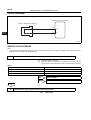
CIRCUIT DIAGRAM
Engine Control Computer
Inlet Air Temperature Sensor
ES
1
55
2
19
THA
E2
G100102J24
INSPECTION PROCEDURE
HINT:
• Read the freeze frame data using the DS-II.Freeze data records aspects of the engine's condition when malfunctions occur.
This information is helpful when troubleshooting.
1
READ DS-II DATA (INTAKE AIR TEMPERATURE)
(a)
(b)
Connect the DS-II to the DLC.
Read the intake air temperature indicated on the DS-II while the
ignition switch is turned to the ON position and the engine is stopped.
Result
Tester Display
Proceed to
-40°C
A
140°C
B
Equivalent to ambient temperature
C
B
GO TO STEP 4
C
CHECK FOR INTERMITTENT PROBLEMS
A
2
READ DS-II DATA (WIRE HARNESS OPEN CIRCUIT INSPECTION)
SST
09843-18020
ES–33
ENGINE CONTROL - EFI SYSTEM (3SZ-VE, K3-VE)
(a)
(b)
Inlet Air Temperature Sensor
Vehicle Side Connector
(c)
(d)
(e)
(+)
(-)
A133551J01
Disconnect the intake air temperature sensor connector.
Short the circuit between terminals 2 (-) and 1 (+) of the inlet air
temperature sensor vehicle side connector using the SST (diagnosis
check wire).
Connect the DS-II to the DLC.
Turn the ignition switch to the ON position.
Read the inlet air temperature displayed on the DS-II.
Standard:
140°C
OK
REPLACE
SENSOR
INTAKE
AIR
TEMPERATURE
ES
NG
3
READ DS-II DATA (CHECK FOR OPEN IN ENGINE CONTROL COMPUTER)
SST
09843-18020
Short the circuit between terminals 55 (THA) and 19 (E2) of the
engine control computer using the SST (diagnosis check wire).
(b) Read the intake air temperature displayed on the DS-II.
Standard:
140°C
(a)
Engine Control Computer
NG
E2
CHECK AND REPLACE ENGINE CONTROL
COMPUTER
THA
A133549J01
OK
REPAIR OR REPLACE WIRE HARNESS OR CONNECTOR
4
READ DS-II DATA (INSPECT WIRE HARNESS SHORT CIRCUIT)
(a)
(b)
(c)
Disconnect the intake air temperature sensor connector.
Turn the ignition switch to the ON position.
Read the intake air temperature displayed on the DS-II.
Standard:
-40°C
OK
NG
REPLACE
SENSOR
INTAKE
AIR
TEMPERATURE
ES–34
5
ENGINE CONTROL - EFI SYSTEM (3SZ-VE, K3-VE)
CHECK WIRE HARNESS
TEMPERATURE SENSOR)
AND
CONNECTOR
(a)
Engine Control Computer
(b)
ES
E2
THA
CONTROL
COMPUTER
INTAKE
Disconnect the engine control computer connector B and the intake
air temperature sensor connector.
Using a tester, check whether there is continuity or a short between
the engine control computer vehicle side connector and the intake air
temperature sensor vehicle side connector.(For terminal layout, see
page ES - 16.)
Standard
Tester Connection (Terminal Symbol)
Engine control computer ←→ Inlet
air temperature sensor
Standard
55(THA) ←→ 1(+)
There is continuity and no shorts
between other terminals and body
ground
19(E2) ←→ 2(-)
There is continuity, and no short
between other terminals
Inlet Air Temperature Sensor
Vehicle Side Connector
NG
(+)
(ENGINE
REPAIR OR REPLACE WIRE HARNESS OR
CONNECTOR
(-)
A133550J01
OK
CHECK AND REPLACE ENGINE CONTROL COMPUTER
ES–35
ENGINE CONTROL - EFI SYSTEM (3SZ-VE, K3-VE)
DTC
P0115/42
COOLANT TEMPERATURE SENSOR SIGNAL
SYSTEM
DESCRIPTION
The resistance of the thermistor built into the coolant temperature sensor varies according to the coolant temperature.
DTC No.
DTC Detection Condition
1. Diagnosis Condition
2. Malfunction Condition
3. Malfunction Time
4. Other
P0115/22
1.
2.
3.
4.
Suspected Area
IG ON
Open or short in coolant temperature circuit
0.5 seconds or more
1 trip
•
•
•
ES
Wire harness or connector
Coolant temperature
Engine control computer
CIRCUIT DIAGRAM
Engine Control Computer
Coolant Temperature
2
54
1
19
THW
E2
G100102J25
INSPECTION PROCEDURE
HINT:
• Read the freeze frame data using the DS-II.Freeze frame data records aspects of the engine's condition when malfunctions
occur. This information is helpful when troubleshooting.
1
READ DS-II DATA (COOLANT TEMPERATURE)
(a)
(b)
Connect the DS-II to the DLC.
Read the engine coolant temperature displayed on the DS-II while the
ignition switch is turned to the ON position and the engine is stopped.
Result
Tester Display
Proceed to
-40 °C
A
140 °C
B
Equivalent to actual coolant temperature
C
B
GO TO STEP 4
ES–36
ENGINE CONTROL - EFI SYSTEM (3SZ-VE, K3-VE)
C
CHECK FOR INTERMITTENT PROBLEMS
A
2
READ DS-II DATA (INSPECT WIRE HARNESS OPEN CIRCUIT)
SST
09843-18020
Disconnect the connector of the coolant temperature sensor.
Short the circuit between terminals 2 (+) and 1 (-) of the water
temperature vehicle side connector using the SST (diagnosis check
wire No.2).
(c) Connect the DS-II to the DLC.
(d) Turn the ignition switch to the ON position.
(e) Read the engine coolant temperature displayed on the DS-II.
Standard:
120°C
(a)
(b)
Coolant Temperature
Vehicle Side Connector
ES
(-)
(+)
A075082J04
OK
REPLACE
SENSOR
COOLANT
TEMPERATURE
NG
3
READ DS-II DATA (CHECK FOR OPEN IN ENGINE CONTROL COMPUTER)
SST
09843-18020
Short the circuit between terminals 54 (THW) and 19 (E2) of the
engine control computer using the SST (diagnosis check wire
No.2).(For terminal layout, see page ES - 16.)
(b) Read the engine coolant temperature displayed on the DS-II.
Standard:
120°C
(a)
Engine Control Computer
NG
E2
THW
CHECK AND REPLACE ENGINE CONTROL
COMPUTER
A133549J02
OK
REPAIR OR REPLACE WIRE HARNESS OR CONNECTOR
4
READ DS-II DATA (INSPECT WIRE HARNESS SHORT CIRCUIT)
(a)
(b)
(c)
Disconnect the connector of the coolant temperature sensor.
Turn the ignition switch to the ON position.
Read the engine coolant temperature displayed on the DS-II.
Standard:
-40°C
OK
REPLACE
SENSOR
COOLANT
TEMPERATURE
ES–37
ENGINE CONTROL - EFI SYSTEM (3SZ-VE, K3-VE)
NG
5
CHECK WIRE HARNESS AND CONNECTOR (ENGINE CONTROL COMPUTER COOLANT
TEMPERATURE)
(a)
(b)
Engine Control Computer
E2
THW
Disconnect connector B of the engine control computer and the
connector of the coolant temperature sensor.
Using a tester, check whether there is continuity or a short between
the vehicle side connector or the engine control computer and the
vehicle side connector of the coolant temperature sensor.(For
terminal layout, see page ES - 16.)
Standard
Tester Connection (Terminal Symbol)
Engine control computer ←→
Coolant temperature
Standard
54(THW) ←→ 2(+)
There is continuity and no short
between other terminals and body
ground
19(E2) ←→ 1(-)
There is continuity, and no short
between other terminals
E.F.I. Coolant Temperature
Vehicle Side Connector
NG
(-)
(+)
REPAIR OR REPLACE WIRE HARNESS OR
CONNECTOR
A133552J01
OK
CHECK AND REPLACE ENGINE CONTROL COMPUTER
ES
ES–38
ENGINE CONTROL - EFI SYSTEM (3SZ-VE, K3-VE)
DTC
P0120/41 THROTTLE SENSOR SIGNAL SYSTEM
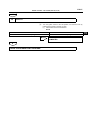
DESCRIPTION
The throttle position sensor is mounted on the throttle body to detect the opening angle of the throttle valve.
When the throttle valve is fully closed, voltage of approximately 0.7 V is applied to the VTH terminal of the engine control
computer.The voltage that is applied to the VTH terminal of the engine control computer increases in proportion to the opening
angle of the throttle valve, and the voltage increases from approximately 3.5 V to 5.0 V when the throttle valve is fully opened.The
engine control computer determines the operating condition of the vehicle by the voltage input from the VTH terminal, and adjusts
the air-fuel ratio, performs fuel-cut control, etc.
ES
Throttle
Position
Sensor
Engine
Control
Computer
VC
5V
VTH
E2
A133572
DTC No.
P0120/41
DTC Detection Condition
1.Diagnosis Condition
2.Malfunction Condition
3.Malfunction Time
4.Other
1. IG ON
2. Open or short circuit in throttle position
sensor circuit
3. 0.5 seconds or more
4. 1 trip
Trouble Area
•
•
•
Throttle position sensor
Wire harness or connector
Engine control computer
ES–39
ENGINE CONTROL - EFI SYSTEM (3SZ-VE, K3-VE)
CIRCUIT DIAGRAM
Engine Control Computer
Throttle Position Sensor
1
B16
56
3
B13
53
2
B6
19
ES
VC
VTH
E2
A133553J01
INSPECTION PROCEDURE
HINT:
• Read the freeze frame data using the DS-II. Freeze frame data records aspects of the engine's condition when malfunctions
occur. This information is helpful when troubleshooting.
1
READ DS-II DATA (ABSOLUTE THROTTLE OPENING ANGLE)
(a)
(b)
Connect the DS-II to the DLC.
Read the opening angle of the throttle valve.
Result
Throttle Valve
OK
FI07052
NG
Standard
Fully open
64-96%
Fully Closed
10-24%
CHECK FOR INTERMITTENT PROBLEMS
ES–40
2
ENGINE CONTROL - EFI SYSTEM (3SZ-VE, K3-VE)
CHECK WIRE HARNESS OR CONNECTOR (CHECK VOLTAGE)
(a)
(b)
(c)
Throttle Position Sensor
Vehicle Side Connector
Disconnect the connector of the throttle position sensor.
Turn the ignition switch to the ON position.
Using a tester, measure the voltage between terminal 1(VC) and 2
(E2) of the vehicle side connector of the throttle position sensor.
Standard:
4.5 to 5.5 V
NG
ES
GO TO STEP 6
E2
VC
A133554J01
OK
3
INSPECT THROTTLE POSITION SENSOR
(a)
(b)
Throttle Position Sensor
Disconnect the connector of the throttle position sensor.
Using a tester, measure the resistance between the connector
terminals of the throttle position sensor.
Standard
Tester Connection
(Terminal Symbol)
3
2
1
Throttle Valve
Resistance
1 (VC) to 3 (VTH)
-
2.5 to 5.9 k
3 (VTH) to 2 (E2)
Fully closed
0.2 to 5.7 k
3 (VTH) to 2 (E2)
Fully open
2.0 to 10.2 k
VC
VTH
E2
A133573J01
NG
REPLACE THROTTLE POSITION SENSOR
OK
4
INSPECT ENGINE CONTROL COMPUTER
SST
09842-97209
(a) Connect the SST (sub harness, EFI computer check) to the engine
control computer.
(b) Turn the ignition switch to the ON position.
(c) Using a tester, measure the voltage between terminal 53 (VTH) and
19 (E2) of the engine control computer connector.(For terminal
layout, see page ES - 16.)
Standard
Engine Control Computer
E2
VTH
A133549J03
OK
Throttle Valve
Standard
Fully closed
0.3 to 1.0 (V)
Fully open
2.7 to 5.2 (V)
CHECK AND REPLACE ENGINE CONTROL
COMPUTER
ES–41
ENGINE CONTROL - EFI SYSTEM (3SZ-VE, K3-VE)
NG
5
CHECK WIRE HARNESS AND CONNECTOR (ENGINE CONTROL COMPUTER THROTTLE
POSITION SENSOR)
(a)
(b)
Engine Control Computer
Disconnect the engine control computer connector B and the throttle
position sensor connector.
Using a tester, check whether there is continuity or a short between
the engine control computer vehicle side connector and the throttle
position sensor vehicle side connector.(For terminal layout, see page
ES - 16.)
Standard
Inspection Terminal (Terminal Name)
Engine control computer ←→
Throttle position sensor
Standard
53 (VTH) ←→ 3 (VTH)
There is continuity and no short
between other terminals and body
ground
VTH
NG
Throttle Position Sensor
Vehicle Side Connector
REPAIR OR REPLACE WIRE HARNESS OR
CONNECTOR
VTH
A133574J01
OK
CHECK AND REPLACE ENGINE CONTROL COMPUTER
6
INSPECT ENGINE CONTROL COMPUTER
SST
09842-97209
Connect the SST (sub harness, EFI computer check) to the engine
control computer.
(b) Turn the ignition switch to the ON position.
(c) Using a tester, measure the voltage between terminals 56 (VC) and
19 (E2) of the engine control computer connector. (For terminal
layout, see page ES - 16.)
Standard:
4.5 to 5.5 V
(a)
Engine Control Computer
NG
E2
VC
A133549J04
CHECK AND REPLACE ENGINE CONTROL
COMPUTER
ES
ES–42
ENGINE CONTROL - EFI SYSTEM (3SZ-VE, K3-VE)
OK
7
CHECK WIRE HARNESS AND CONNECTOR (ENGINE CONTROL COMPUTER THROTTLE
POSITION SENSOR)
(a)
(b)
Engine Control Computer
ES
E2
Disconnect the engine control computer connector B and the throttle
position sensor connector.
Using a tester, check whether there is continuity or a short between
the engine control computer vehicle side connector and the throttle
position sensor vehicle side connector.(For terminal layout, see page
ES - 16.)
Standard
Inspection Terminal (Terminal Name)
Engine control computer ←→
Throttle position sensor
Standard
56 (VC) ←→ 1 (VC)
There is continuity and no short
between other terminals and body
ground
19 (E2) ←→ 2 (E2)
There is continuity, and no short
between other terminals
VC
Throttle Position Sensor
Vehicle Side Connector
OK
VC
CHECK AND REPLACE ENGINE CONTROL
COMPUTER
E2
A133574J03
NG
REPAIR OR REPLACE WIRE HARNESS OR CONNECTOR
ES–43
ENGINE CONTROL - EFI SYSTEM (3SZ-VE, K3-VE)
DTC
P0130/21 FRONT 02 SENSOR SIGNAL SYSTEM
DESCRIPTION
A three-way catalytic converter is used to efficiently remove CO, HC and NOx from the exhaust gas. The three-way catalytic
converter works most efficiently when the air-fuel ratio is close to the stoichiometric ratio.Therefore, if the engine does not operate
close to the stoichiometric air-fuel ratio. CO, HC and NOx cannot be converted efficiently. An oxygen sensor is provided in order
help the system maintain the stoichiometric ratio. The oxygen sensor is used to detect the oxygen concentration of the exhaust
gas. The oxygen sensor has a characteristic where its voltage output changes suddenly near the stoichiometric air-fuel ratio, if
normal combustion is occurring. The engine control computer uses this signal characteristic to allow air-fuel ratio control. When
the air-fuel ratio is lean, the oxygen level in the exhaust gas increases. The engine control computer recognizes the lean air-fuel
ratio detected by the oxygen sensor. (Low voltage variation: < 0.45 V) When the air-fuel ratio is rich, oxygen levels in the exhaust
gas decrease, and the engine control computer recognizes the rich air-fuel ratio detected by the oxygen sensor. (High voltage
variation: > 0.45 V) The engine control computer determines whether the air-fuel ratio is rich or lean by the electromotive force
signal of the oxygen sensor, and controls injection volume. The oxygen sensor has a heater which warms a zirconium element.
The heater is controlled by the engine control computer, which applies current to the heater in order to prevent sensor inaccuracy
that may occur if the sensor gets cold when the exhaust gas temperature is low (such as when there is a low amount of intake
air).
Atmosphere
Output Voltage
Air-Fuel Ratio
Housing
Platinum Electrode
Zirconia Element
Platinum Electrode
Heater
Lean
Rich
Stoichiometric Air-Fuel Ratio
Ceramic Coating
Cover
Exhaust Gas
DTC Detection Condition
1.Diagnosis Condition
2.Malfunction Condition
3.Malfunction Time
4.Other
DTC No.
P0130/21
A069512
1. Engine warmed up and engine speed lower than 2,500 r/min
2. Steady oxygen sensor output voltage of less than 0.3 V or more
than 0.6 V
3. 400 seconds or more after engine started
4. 2 trip
Suspected Area
•
•
•
Wire harness or connector
Oxygen sensor
Engine control computer
HINT:
Using the DS-II, check the FrO2 sensor output voltage on the data monitor screen. If the FrO2 sensor output voltage stays at 0.02
V or less, the O2 sensor voltage system circuit may be open.
DESCRIPTION
1.
Start the engine and drive the vehicle for more than 20 seconds at speed above 10 km/h.[*1]
2.
Allow the engine to idle for approximately 400 seconds.[*2]
3.
Check the voltage of the FrO2 sensor output.
NOTICE:
If this test is not performed accurately, it will be impossible to determine exactly where problems are occurring.
ES
ES–44
ENGINE CONTROL - EFI SYSTEM (3SZ-VE, K3-VE)
HINT:
If there are any abnormalities, the check warning light will remain on while the procedure is performed. [*2].
Vehicle Speed
More Than 20 Sec.[*1]
10 km/h
ES
IG OFF
Idling More Than 400 Sec. [*2]
A140624J01
CIRCUIT DIAGRAM
Engine Control Computer
EFI Relay
EFI
39
MRO
Front O2 Sensor
2
1
15
3
123
OXH1
MAIN
4
OX1
Rear O2 Sensor
2
Battery
4
1
3
14
18
19
OXH2
OX2
E2
A135516
ES–45
ENGINE CONTROL - EFI SYSTEM (3SZ-VE, K3-VE)
INSPECTION PROCEDURE
HINT:
Read the freeze frame data using the DS-II.Freeze frame data records aspects of the engine's condition when malfunctions
occur. This information is helpful when troubleshooting.
1
READ DS-II DATA (FrO2 SENSOR OUTPUT VOLTAGE)
(a)
(b)
Connect the DS-II to the DLC.
Start the engine and warm it up until it reaches a temperature that
allows the oxygen sensor to start feedback.
(c) Warm up the oxygen sensor for approximately 90 seconds at an
engine speed of 2500 r/min.
(d) Using the DS-II, read FrO2 sensor voltage B1S1 while the engine is
idling.
Result:
Repeated output of voltage that is less than 0.3 V or more than 0.6 V.
HINT:
• It is easier to see the changes in the line graph mode on the monitor
screen.
OK
GO TO STEP 3
NG
2
CHECK WIRE HARNESS AND CONNECTOR (ENGINE CONTROL COMPUTER OXYGEN SENSOR)
(a)
Engine Control Computer
E2
(b)
Disconnect the engine control computer connector B and the oxygen
sensor connector.
Using a tester, check whether there is continuity or a short between
the engine control computer and the oxygen sensor (For terminal
layout, see page ES - 16).
Standard
Tester Connection (Terminal Symbol)
Engine control computer ←→
Oxygen sensor
Standard
123 (OX1) ←→ 3 (OX1)
There is continuity and no short
between other terminals and body
ground
19 (E2) ←→ 4 (E2)
There is continuity, and no short
between other terminals
OX1
Oxygen Sensor
Vehicle Side Connector
NG
OX1
E2
A133576J04
OK
REPLACE OXYGEN SENSOR
REPAIR OR REPLACE WIRE HARNESS OR
CONNECTOR
ES
ES–46
3
ENGINE CONTROL - EFI SYSTEM (3SZ-VE, K3-VE)
ROAD TEST TO CHECK OPERATION
(a)
(b)
(c)
ES
Connect the DS-II to the DLC.
Turn the ignition switch to the ON position, and delete the DTCs by
following the prompts on the DS-II screen.
To check the system, warm up the oxygen sensor by performing a
road test.
HINT:
Refer to DESCRIPTION for the procedure.
NEXT
4
READ DTCS
(a)
(b)
Connect the DS-II to the DLC.
Turn the ignition switch to the ON position, and read the DTCs by
following the prompts on the DS-II screen.
(1) Check if DTC P0130/21 is indicated.
Result
Tester Display
Proceed to
Indicates P0130/21
A
Indicates a normal code
B
B
CHECK FOR INTERMITTENT PROBLEMS
A
CHECK AND REPLACE ENGINE CONTROL COMPUTER
ES–47
ENGINE CONTROL - EFI SYSTEM (3SZ-VE, K3-VE)
DTC
P0135/23 FRONT 02 SENSOR HEATER SIGNAL SYSTEM
DTC
P0141/24 REAR 02 SENSOR HEATER
DESCRIPTION
See ES - 43.
DTC Detection Condition
1.Diagnosis Condition
2.Malfunction Condition
3.Malfunction Time
4.Other
DTC No.
Suspected Area
ES
P0135/23
1.
2.
3.
4.
IG ON
Open in oxygen sensor heater circuit
1.2 seconds or more
2 trip
•
•
•
Wire harness or connector
Oxygen sensor
Engine control computer
P0141/24
1.
2.
3.
4.
IG ON
Open in oxygen sensor No.2 heater circuit
1.2 seconds or more
2 trip
•
•
•
Wire harness or connector
OXYGEN SENSOR NO.2
Engine control computer
CIRCUIT DIAGRAM
HINT:
For the wiring diagram, see page ES - 44.
INSPECTION PROCEDURE
HINT:
Read the freeze frame data using the DS-II.Freeze frame data records aspects of the engine's condition when malfunctions
occur. This information is helpful when troubleshooting.
1
INSPECT OXYGEN SENSOR
(a)
(b)
+B
Front Rear O2 Sensor
HT1A HT2A
2
4
E2
Disconnect the oxygen sensor connector.
CHECK SENSOR HEATER RESISTANCE
(1) Using a tester, measure the resistance between the terminals.
Standard
Sensor
Tester Connection
(Terminal Symbol)
Standard (Measurement
Condition)
Oxygen sensor
2 (+B) ←→ 1 (HT1A)
5 to 10 (20°C)
Oxygen sensor No.2
2 (+B) ←→ 1 (HT2A)
5 to 10 (20°C)
1
3
(c)
A133577J02
Check short in sensor heater
(1) Using the tester, check for the short between terminals 1
(HT1A) and 4 (E2).
Standard
Sensor
Tester Connection
(Terminal Symbol)
Standard
Oxygen sensor
1 (HT1A) ←→ 4 (E2)
No continuity
Oxygen sensor No.2
1 (HT2A) ←→ 4 (E2)
No continuity
NG
REPLACE OXYGEN SENSOR
ES–48
ENGINE CONTROL - EFI SYSTEM (3SZ-VE, K3-VE)
OK
2
CHECK WIRE HARNESS AND CONNECTOR (SENSOR HEATER POWER SOURCE CIRCUIT)
(a)
(b)
(c)
Oxygen Sensor
Vehicle Side Connector
+B
ES
A133578J01
Disconnect the oxygen sensor connector.
Turn the ignition switch to the ON position.
Using a tester, measure the voltage of the terminals of the oxygen
sensor vehicle side connecter.
Standard
Installed position
Tester Connection
(Terminal Symbol)
Standard
Front, rear
2 (+B) ←→ body ground
10 to 14 V
NG
GO TO STEP 4
OK
3
CHECK WIRE HARNESS AND CONNECTOR (ENGINE CONTROL COMPUTER OXYGEN SENSOR)
(a)
Engine Control Computer
OXH1
(b)
Disconnect the engine control computer connector B and the oxygen
sensor connector.
Using a tester, check whether there is continuity or a short between
the engine control computer and the oxygen sensor. (For terminal
layout, see page ES - 16.)
Standard
Tester Connection (Terminal Symbol)
Engine control computer ←→
Oxygen sensor
Standard
15 (OXH1) ←→ 1 (HT1A)
There is continuity and no short
between other terminals and body
ground
14 (OXH2) ←→ 1 (HT2A)
There is continuity and no short
between other terminals and body
ground
OXH2
02 Sensor Vehicle Side Connector
HT1A HT2A
NG
REPAIR OR REPLACE WIRE HARNESS OR
CONNECTOR
A133576J03
OK
CHECK AND REPLACE ENGINE CONTROL COMPUTER
4
CHECK WIRE HARNESS AND CONNECTOR (OXYGEN SENSOR EFI RELAY)
(a)
Disconnect the oxygen sensor connector.
ENGINE CONTROL - EFI SYSTEM (3SZ-VE, K3-VE)
(b)
(c)
Oxygen Sensor
Vehicle Side Connector
+B
ES–49
Remove the EFI relay.
Using a tester, check whether there is continuity or a short between
the relay block holder for the EFI relay and the oxygen sensor.
Standard
Installed position
Front, rear
NG
Tester Connection
(Terminal Symbol)
Relay block holder for
EFI relay ←→ Oxygen
sensor
3 ←→ 2 (+B)
Standard
There is continuity and
no short between other
terminals and body
ground
REPAIR OR REPLACE WIRE HARNESS OR
CONNECTOR
2
5 3
1
A133579J01
OK
CHECK ECU POWER SOURCE SYSTEM (SEE ECU POWER SOURCE SYSTEM)
ES
ES–50
ENGINE CONTROL - EFI SYSTEM (3SZ-VE, K3-VE)
DTC
P0136/22 REAR 02 SENSOR SIGNAL SYSTEM
DESCRIPTION
(See Page ES - 43)
DTC Detection Condition
1.Diagnosis Condition
2.Malfunction Condition
3.Malfunction Time
4.Other
DTC No.
ES
P0136/27
Suspected Area
1. During feedback after engine is warmed up
2. Open in oxygen sensor circuit or no rich signals are input
during feedback
3. 500 seconds or more
4. 2 trip
•
•
•
Wire harness or connector
Oxygen sensor No.2
Engine control computer
HINT:
• Using the DS-II, check the RrO2 sensor output voltage on the data monitor screen. If the RrO2 sensor output voltage stays at
0.1 V or less, there be an open in the RrO2 sensor voltage circuit.
• The conditions of the oxygen sensor No.2 output voltage and the air-fuel ratio feedback (F/B calibration value) can be read by
using DS-II.
DESCRIPTION
1.
Start the engine and drive the vehicle for more than 20 seconds at speed above 10 km/h.[*1]
2.
Allow the engine to idle for approximately 400 seconds.[*2]
3.
Warm up the engine. [*3]
4.
Drive the vehicle for 50 seconds or more at a vehicle speed of 70 km/h or more. [*4]
5.
Check the voltage of the RrO2 sensor output.
NOTICE:
If this test is not performed accurately, it will be impossible to determine exactly where problems are occurring.
HINT:
• Because oxygen sensor No.2 does not have heater control, drive with a moderate level of load after the engine is
completely warmed up.
• If there are any abnormalities, the check engine warning light will remain on while the procedure is performed. [*4].
Vehicle Speed
More Than 50 Sec. [*4]
70 km/h
More Than 20 Sec. [*1]
10 km/h
IG OFF
Idling More Than 400 Sec. [*2]
Driving With The
Engine Warm [*3]
A140625J01
CIRCUIT DIAGRAM
(See Page ES - 44)
ES–51
ENGINE CONTROL - EFI SYSTEM (3SZ-VE, K3-VE)
INSPECTION PROCEDURE
HINT:
Read the freeze frame data using the DS-II.Freeze frame data records aspects of the engine's condition when malfunctions
occur. This information is helpful whnen troubleshooting.
1
READ DTCs
(a)
(b)
(c)
(d)
Connect the DS-II to the DLC.
Turn the ignition switch to the ON position, and delete the DTCs by
following the prompts on the DS-II screen.(See page ES - 8.)
Perform a road test.
Check for DTCs following the prompts on the DS-II screen. (See
page ES - 8.)
(1) Check if DTC P0136/27 is indicated.
Result
Tester Display
Proceed to
Indicates P0136/27
A
Indicates P036/27 and other codes
B
Indicates a normal code
C
HINT:
If DTC P0136/27 and other DTCs are output at the same time,
check the other codes first.
A
B
GO TO RELEVANT DTC CHART
C
CHECK FOR INTERMITTENT PROBLEMS
ES
ES–52
2
ENGINE CONTROL - EFI SYSTEM (3SZ-VE, K3-VE)
CHECK WIRE HARNESS AND CONNECTOR (ENGINE CONTROL COMPUTER OXYGEN SENSOR
NO.2)
(a)
Engine Control Computer
(b)
ES
E2
Disconnect the engine control computer connector B and the oxygen
sensor No.2 connector.
Using a tester, check whether there is continuity or a short between
the engine control computer and oxygen sensor No.2. (For terminal
layout, see page ES - 16.)
Standard
Tester Connection (Terminal Symbol)
Engine Control Computer ←→
Oxygen Sensor No.2
Standard
18 (O2X2) ←→ 1 (+)
There is continuity and no short
between other terminals and body
ground
19(E2) ←→ 2(-)
There is continuity, and no short
between other terminals
OX2
Rear O2 Sensor
Vehicle Side Connector
NG
1 2
(+)
REPAIR OR REPLACE WIRE HARNESS OR
CONNECTOR
(-)
A133580J01
OK
3
READ DS-II DATA (RrO2 SENSOR OUTPUT VOLTAGE)
(a)
(b)
(c)
(d)
Connect the DS-II to the DLC.
Following the prompts on the DS-II screen, select ECU DATA
MONITOR, then RrO2 SENSOR OUTPUT VOLTAGE. Then select
MODE CHANGE and LINE GRAPH.
Warm up oxygen sensor No.2 for approximately 90 seconds at an
engine speed of 2500 r/min.
Read the voltage of the RrO2 sensor output while racing the engine
at a speed of 4000 r/min several times.
Result:
Voltage output is 0.4 V or less and 0.5 V or more
HINT:
• Oxygen sensor No.2 does not have a heater control, so perform
the tests after the engine is completely warm.
• If changes are difficult to see, perform a road test.
NG
OK
REPLACE ENGINE CONTROL COMPUTER
REPLACE OXYGEN SENSOR NO.2
ES–53
ENGINE CONTROL - EFI SYSTEM (3SZ-VE, K3-VE)
DTC
P0171/25 FUEL SYSTEM (LEAN MALFUNCTION)
DTC
P0172/26 FUEL SYSTEM (RICH MALFUNCTION)
DESCRIPTION
There are two types of air-fuel ratio corrections. One is the normal operating air-fuel ratio correction (air-fuel ratio F/B). The other
is the memory air-fuel ratio correction (air-fuel ratio F/B learned). Air-fuel ratio F/B is the air-fuel ratio correction that is used to
maintain a stoichiometric ratio. The oxygen sensors send signals to the engine control computer indicating whether the current
air-fuel ratio is rich or lean comparing to the stoichiometric ratio. When the signal indicates that the condition is rich the injection
volume is decreased. When the signal indicates that the condition is lean the injection volume is increased. Air-fuel ratio F/B
learned value refers to a value that shows the air-fuel ratio F/B value over a long period of time. Because of differences specific to
each engine (such as differences caused by wear over time and changes in the operating environment) this air-fuel ratio F/B
learned value varies from a central value.If either the air-fuel ratio F/B value or the air-fuel ratio F/B learned value exceeds a
certain value and becomes lean or rich, the engine control computer illuminates the check warning light.
DTC Detection Condition
1.Diagnosis Condition
2.Malfunction Condition
3.Malfunction Time
4.Other
DTC No.
Suspected Area
P0171/25
1. While operating the vehicle at 70 km/h with the engine
warm, during a normal air-fuel ratio F/B
2. Fuel trim is corrected heavily on the increase side
(approx.+ 40 %)
3. 60 seconds or more
4. 2 trip
•
•
•
•
•
•
•
Intake system
Fuel system
Ignition system
Wire harness or connector
Oxygen sensor
Engine control computer
Gas leakage from exhaust system
P0172/26
1. While operating the vehicle at 70 km/h with the engine
warm, during a normal air-fuel ratio F/B
2. Fuel trim is corrected heavily on the decrease side
(approx.+ -35%)
3. 60 seconds or more
4. 2 trip
•
•
•
•
•
•
•
Intake system
Fuel system
Ignition system
Wire harness or connector
Oxygen sensor
Engine control computer
Gas leakage from exhaust system
HINT:
If the total of the air-fuel F/B value and the air-fuel F/B learned value is within 25%, the system is normal.
CIRCUIT DIAGRAM
See Page ES - 44.
INSPECTION PROCEDURE
HINT:
• Check if the engine has stopped in the past because of a fuel cut.If so, the DTC P0171/25 may be recorded.
• Read the freeze frame data using the DS-II.Freeze frame data records aspects of the engine's condition when malfunctions
occur. This information is helpful when troubleshooting.
1
INSPECT EMISSION CONTROL SYSTEM
HINT:
For inspection procedures, see page EC - 1.
NG
REPAIR OR REPLACE EMISSION CONTROL
SYSTEM
ES
ES–54
ENGINE CONTROL - EFI SYSTEM (3SZ-VE, K3-VE)
OK
2
INSPECT FUEL INJECTOR ASSEMBLY
SST
09843-97201, O9268-41047
Check the resistance.
(1) Using the tester, measure the resistance between the injector
terminals.
Resistance:
12 (20°C)
HINT:
If the value is not within the standard range, replace with a
known-good part.
(b) Fuel injection volume
NOTICE:
Work in a location with good air ventilation and watch out for
fire.
(1) Connect the SST (injection measuring tool set) to the fuel pipe
(vehicle side).
NOTICE:
Be extremely careful when handling the fuel tube
connector.
(2) Attach the injector to a graduated cylinder.
HINT:
To prevent fuel from spraying, install the correct-sized vinyl
tube, etc.
(3) Connect the DS-II to the DLC and operate the fuel pump.
(4) Connect the injector to the SST (EFI inspection wire).
(5) Connect the SST (EFI inspection wire) to the battery, perform
fuel injection (15 seconds each) 2 or 3 times, and calculate the
average value.
SST:
09842-30055
Standard
(a)
ES
A
Injector
B
Fuel Pipe
A139327
(c)
Difference Between Individual
Injectors
60 to 73ml
13 ml or less
HINT:
If the value is not within the standard range, replace with
known-good parts.
Check for leakage.
(1) When removing the SST from the battery under the conditions
described above, check that there is no leakage from the
injector.
Standard:
1 drop or less per 12 minutes
NG
B000069
Injection Volume
REPLACE FUEL INJECTOR ASSEMBLY
ES–55
ENGINE CONTROL - EFI SYSTEM (3SZ-VE, K3-VE)
OK
3
CHECK COOLANT TEMPERATURE
(a)
Check the resistance.
(1) Using the tester, inspect the resistance between the terminals.
Standard
Measurement Condition
Standard
When approx. 20°C
2.32 to 2.59 kΩ
When approx. 80°C
0.310 to 0.326 kΩ
NOTICE:
Protect the terminal area from getting wet when checking
the sensor by applying water.Also, wipe the sensor dry
after the check.
NG
Resistance
REPLACE
SENSOR
COOLANT
TEMPERATURE
[kΩ]
Temperature [°C]
A050330
OK
4
INSPECT THE IGNITION SYSTEM
HINT:
For inspection procedures, see page IG - 1.
NG
REPAIR OR REPLACE IGNITION SYSTEM
OK
5
CHECK FUEL SYSTEM
HINT:
For inspection procedures, see page FU - 3.
NG
REPAIR OR REPLACE FUEL SYSTEM
NG
REPAIR OR REPLACE
LEAKAGE AREA
OK
6
CHECK FOR EXHAUST GAS LEAKS
EXHAUST
GAS
ES
ES–56
ENGINE CONTROL - EFI SYSTEM (3SZ-VE, K3-VE)
OK
7
READ DS-II DATA (FrO2 SENSOR OUTPUT VOLTAGE)
(a)
(b)
ES
Warm up the oxygen sensor for approx. 90 seconds at an engine
speed of 2500 r/min.
Using the DS-II, read the output voltage of the oxygen sensor while
the engine is idling.
Standard:
Repeated output of voltage that is less than 0.3 V or
more than 0.6 V
OK
GO TO STEP 9
NG
8
CHECK WIRE HARNESS AND CONNECTOR (ENGINE CONTROL COMPUTER OXYGEN SENSOR)
(a)
(b)
(c)
Engine Control Computer
Disconnect connector B of the engine control computer.
Disconnect the connector of the oxygen sensor.
Using a tester, check whether there is continuity or a short between
the engine control computer and the oxygen sensor connector.(For
terminal layout, see page ES - 16.)
Standard
Tester Connection (Terminal Symbol)
Engine Control Computer ←→ Oxygen
Sensor
Standard
123 (OX1) ←→ 3 (OX1)
There is continuity and no short
between other terminals and body
ground
OX1
Front O2 Sensor
Vehicle Side Connector
OK
REPLACE OXYGEN SENSOR
NG
REPAIR OR REPLACE WIRE HARNESS OR
CONNECTOR
OX1
A133576J02
9
ROAD TEST TO CHECK OPERATION
(a)
(b)
(c)
Connect the DS-II to the DLC.
Turn the ignition switch to the ON position, and delete the DTCs by
following the prompts on the DS-II screen.
To check the system, warm up the oxygen sensor by performing a
road test.
HINT:
Refer to the oxygen sensor output voltage inspection procedure.
ES–57
ENGINE CONTROL - EFI SYSTEM (3SZ-VE, K3-VE)
GO
10
READ DTCs
(a)
(b)
Connect the DS-II to the DLC.
Turn the ignition switch to the ON position, and read the DTC by
following the prompts on the DS-II screen.
(1) Check if DTC P0171/25 is detected.
Result
A
B
P0171/25 is not output again
P0171/25 is output again
B
A
CHECK FOR INTERMITTENT PROBLEMS
CHECK AND REPLACE ENGINE CONTROL
COMPUTER
ES
ES–58
ES
ENGINE CONTROL - EFI SYSTEM (3SZ-VE, K3-VE)
DTC
P0300/17 MISFIRE
DTC
P0301/17 MISFIRE (#1 CYLINDER)
DTC
P0302/17 MISFIRE (#2 CYLINDER)
DTC
P0303/17 MISFIRE (#3 CYLINDER)
DTC
P0304/17 MISFIRE (#4 CYLINDER)
DESCRIPTION
The igniter detects ionic current that is generated by combustion. This ionic current is represented by ionic voltage and input to
the engine control computer.If the voltage is lower than the specified value, the engine control computer determines that there
has been a misfire and counts the number of detected misfires. If the number of misfires reaches or exceeds a specified value,
the engine check warning light illuminates to indicate a problem. If the number of misfires reaches or exceeds the point at which
the catalyst may overheat, the engine check warning light flashes.
DTC No.
DTC Detection Condition
1.Diagnosis Condition
2.Malfunction Condition
3.Malfunction Time
4.Other
Suspected Area
P0300/17
1. When driving at vehicle speed of 30 to 70
km/h
2. DTCs P0301/17 through P0304/17 are
output repeatedly
3. 60 seconds or more
4. 2 trip
•
•
•
•
•
•
•
Ignition system
Intake system
Fuel system
Wire harness or connector
Coolant temperature
Engine control computer
Fuel injector
P0301/17
1. When driving at vehicle speed of 30 to 70
km/h
2. Rate of misfires is higher than the set
value
3. 60 seconds or more
4. 2 trip
•
•
•
•
•
•
•
Ignition system
Intake system
Fuel system
Wire harness or connector
Coolant temperature
Engine control computer
Fuel injector
P0302/17
1. When driving at vehicle speed of 30 to 70
km/h
2. Rate of misfires is higher than the set
value
3. 60 seconds or more
4. 2 trip
•
•
•
•
•
•
•
Ignition system
Intake system
Fuel system
Wire harness or connector
Coolant temperature
Engine control computer
Fuel injector
P0303/17
1. When driving at vehicle speed of 30 to 70
km/h
2. Rate of misfires is higher than the set
value
3. 60 seconds or more
4. 2 trip
•
•
•
•
•
•
•
Ignition system
Intake system
Fuel system
Wire harness or connector
Coolant temperature
Engine control computer
Fuel injector
P0304/17
1. When driving at vehicle speed of 30 to 70
km/h
2. Rate of misfires is higher than the set
value
3. 60 seconds or more
4. 2 trip
•
•
•
•
•
•
•
Ignition system
Intake system
Fuel system
Wire harness or connector
Coolant temperature
Engine control computer
Fuel injector
ES–59
ENGINE CONTROL - EFI SYSTEM (3SZ-VE, K3-VE)
CIRCUIT DIAGRAM
Ignition Coil Assembly
( No. 1 Cylinder)
To E/G Fuse
Engine Control Computer
1
3
A11
4
2
B11
Injector No. 1
IG1
#10
A4
2
1
ICMB1
Ignition Coil Assembly
( No. 2 Cylinder)
Injector No. 2
1
3
A10
4
2
B10
#20
IG2
A3
2
ES
1
ICMB2
Injector No. 3
Ignition Coil Assembly
( No. 3 Cylinder)
#30
1
3
A9
4
2
B9
ICMB3
A8
4
2
B8
1
Injector No. 4
#40
3
2
IG3
Ignition Coil Assembly
( No. 4 Cylinder)
1
A2
A1
2
1
IG4
ICMB4
To EFI Relay
A135528
INSPECTION PROCEDURE
HINT:
• If any codes are detected other than misfire malfunction, perform troubleshooting for those DTCs first.
• Read the freeze frame data using the DS-II.Freeze frame data records aspects of the engine's condition when malfunctions
occur. This information is helpful when troubleshooting.
• To confirm that the repair has been completed, operate the vehicle using one of the driving patterns shown below.
Driving patterns
Engine speed
Time
Idle
3 and a half minutes or more
1000 r/min
3 minutes or more
2000 r/min
1 and a half minutes or more
3000 r/min
1 minute or more
1
INSPECT THE IGNITION SYSTEM
(See page IG - 1)
NG
OK
REPAIR OR REPLACE IGNITION SYSTEM
ES–60
2
ENGINE CONTROL - EFI SYSTEM (3SZ-VE, K3-VE)
CHECK FUEL PRESSURE
(See page FU - 3)
NG
REPAIR OR REPLACE FUEL SYSTEM
OK
ES
3
CHECK COOLANT TEMPERATURE
(a)
Check the resistance.
(1) Using the tester, inspect the resistance between the terminals.
Standard:
At approx. 20°C : 2.32 to 2.59 kΩ
At approx. 80°C : 0.310 to 0.326 kΩ
NOTICE:
Protect the terminal area from getting wet when checking
the sensor by applying water. Also, wipe the sensor dry
after the check.
NG
REPLACE
SENSOR
COOLANT
TEMPERATURE
Resistance
[kΩ]
Temperature [°C]
A050330
OK
4
INSPECT FUEL INJECTOR ASSEMBLY
SST
09843-97201, O9268-41047
Check the resistance.
(1) Using the tester, measure the resistance between the injector
terminals.
Standard:
12 Ω (20°C)
HINT:
If the value is not within the standard range, replace with
known-good parts.
(b) CHECK INJECTION VOLUME
NOTICE:
Work in a location with good air ventilation and watch out for
fire.
(1) Connect the SST (injection measuring tool set) to the fuel pipe
(vehicle side).
(a)
ES–61
ENGINE CONTROL - EFI SYSTEM (3SZ-VE, K3-VE)
(2)
(3)
(4)
(5)
A
Injector
B
Fuel Pipe
A139327
(c)
NOTICE:
Be extremely careful when handling the fuel tube
connector.
Attach the injector to a graduated cylinder.
HINT:
To prevent fuel from spraying, install the correct-sized vinyl
tube, etc.
Connect the DS-II to the DLC and operate the fuel pump.
Connect the injector to the SST (EFI inspection wire).
Connect the SST (EFI inspection wire) to the battery, perform
fuel injection (15 seconds each) 2 or 3 times, and calculate the
average value.
Standard
Injection Volume
Difference Between Individual
Injectors
60 to 73 ml
13ml or less
HINT:
If the value is not within the standard range, replace with
known-good parts.
Check for leakage.
(1) When removing the SST from the battery under the conditions
described above, check that there is no leakage from the
injector.
Standard:
1 drop or less per 12 minutes
NG
REPLACE FUEL INJECTOR ASSEMBLY
B000069
OK
5
CHECK VACUUM SENSOR
(a)
(b)
Intake Pressure Sensor
1
2
Tester Connection (Terminal Symbol)
Standard
3 (VC) ←→ 1 (E2)
4.5 to 5.5 V
2 (PIM) ←→ 1 (E2)
3.1 to 4.1V
3
(c)
E2
PIM
Turn the ignition switch to the ON position.
Measure the voltage between the terminals of the vacuum sensor
connecter using the tester.
Standard
VC
A133547J01
Remove the fuel pump relay and crank the engine, then measure the
voltage between the terminals of the vacuum sensor connector.
Standard
Tester Connection (Terminal Symbol)
Standard
2 (PIM) ←→ 1 (E2)
Voltage value fluctuates
NG
OK
REPLACE THE VACUUM SENSOR
ES
ES–62
6
ENGINE CONTROL - EFI SYSTEM (3SZ-VE, K3-VE)
CHECK WIRE HARNESS AND CONNECTOR
(a)
(b)
Disconnect connector A of the engine control computer and
disconnect the connectors of each fuel injector.
Using a tester, check whether there is continuity or a short between
the engine control computer vehicle side connector and the fuel
injector vehicle side connector.
Standard
Installed position
ES
#1 Cylinder
#2 Cylinder
#3 Cylinder
#4 Cylinder
NG
Terminal Connection
(Terminal Symbol)
Standard
2←→24(#10)
There is continuity and
no short between other
terminals and body
ground
2←→23(#20)
There is continuity and
no short between other
terminals and body
ground
2←→22(#30)
There is continuity and
no short between other
terminals and body
ground
2←→21(#40)
There is continuity and
no short between other
terminals and body
ground
REPAIR OR REPLACE WIRE HARNESS OR
CONNECTOR
OK
CHECK AND REPLACE ENGINE CONTROL COMPUTER
ES–63
ENGINE CONTROL - EFI SYSTEM (3SZ-VE, K3-VE)
DTC
P0325/18 KNOCK SENSOR SIGNAL SYSTEM
DESCRIPTION
The knock control sensor is mounted to the cylinder block to detect engine knocking.Inside the knock control sensor, there is a
sensing element. When the sensing element is deformed due to the cylinder block vibration caused by knocking, it generates
electricity. When the engine computer senses this voltage, it retards the ignition timing to control the knocking.
DTC Detection Condition
1.Diagnosis Condition
2.Malfunction Condition
3.Malfunction Time
4.Other
DTC No.
P0325/52
1.
2.
3.
4.
Suspected Area
IG ON
Open or short in knock control sensor circuit
0.9 seconds or more
1 trip
•
•
•
•
Wire harness or connector
Knock control sensor
Installation tightness of knock control sensor
Engine control computer
CIRCUIT DIAGRAM
Engine Control Computer
Knock Control Sensor
Shield Line
2
121
1
19
KNK
E2
A133581J01
INSPECTION PROCEDURE
HINT:
Read the freeze frame data using the DS-II.Freeze frame data records aspects of the engine's condition when malfunctions
occur. This information is helpful when troubleshooting.
ES
ES–64
1
ENGINE CONTROL - EFI SYSTEM (3SZ-VE, K3-VE)
INSPECT ENGINE CONTROL COMPUTER
HINT:
The communication between the engine control computer and the knock
control sensors can be checked using the oscilloscope function of the DSII.
(a) Connect the DS-II to terminals 121(KNK) and 19 (E2) of the engine
control computer connectors.(For terminal layout, see page ES - 16.)
Engine Control Computer
ES
E2
KNK
A133549J05
(b)
Set the DS-II to the oscilloscope function.(See the DS-II instruction
manual for the setting procedures.)
Item
Tester Connection
Tool setting
Measurement condition
Condition
KNK ←→ E2
1 V/DIV, 1 ms/DIV
Engine is warmed up and an engine speed of
4000 r/min is maintained
HINT:
• The oscilloscope waveform shown as an example does not
include noise or chattering waveforms.
• The waveform amplitudes differ slightly depending on the vehicle.
A134287
OK
CHECK AND REPLACE ENGINE CONTROL
COMPUTER
NG
2
INSPECT SENSOR INSTALLATION PART
(a)
Check the condition of the knock control sensor installation.
NG
REPAIR
OR
REPLACE
INSTALLATION PART
SENSOR
OK
3
CHECK WIRE HARNESS AND CONNECTOR (ENGINE CONTROL COMPUTER KNOCK CONTROL
SENSOR)
(a)
Disconnect the engine control computer connector B and the knock
control sensor connector.
ES–65
ENGINE CONTROL - EFI SYSTEM (3SZ-VE, K3-VE)
(b)
Engine Control Computer
E2
Using a tester, check whether there is continuity or a short between
the engine control computer and the knock control sensor(For
terminal layout, see page ES - 16.)
Standard
Tester Connection (Terminal Symbol)
Engine Control Computer ←→
Knock Control Sensor
Standard
121 (KNK) ←→ 2 (+)
There is continuity and no short
between other terminals and body
ground
19(E2) ←→ 1(-)
There is continuity and no short
between other terminals and body
ground
KNK
Knock Control Sensor
Vehicle Side Connector
NG
(-)
REPAIR OR REPLACE WIRE HARNESS OR
CONNECTOR
(+)
A133582J01
OK
4
REPLACE KNOCK CONTROL SENSOR
(a)
(b)
(c)
(d)
Replace the knock control sensor.(See page ES - 133, ES - 134.)
Connect the DS-II to the DLC.
Turn the ignition switch to the ON position, and delete the DTC
memory by following the prompts on the DS-II screen.
Perform a road test.
GO
5
READ DTCs
(a)
(b)
Connect the DS-II to the DLC.
Turn the ignition switch to the ON position, and read the DTCs by
following the prompts on the DS-II screen.
(1) Check if DTC P0325/52 is detected.
Result
A
B
Indicates P0325/52
Does not indicate P0325/52
B
SYSTEM NORMAL
A
CHECK AND REPLACE ENGINE CONTROL COMPUTER
ES
ES–66
ENGINE CONTROL - EFI SYSTEM (3SZ-VE, K3-VE)
DTC
P0335/13
ENGINE
SYSTEM
REVOLUTION
SENSOR
SIGNAL
DESCRIPTION
The crank position sensor system consists of the crank angle sensor plate No.1 and the pickup coil. The crank angle sensor is
installed on the crankshaft. It has 30 teeth with 6 missing teeth to allow top dead center to be detected. The NE signal sensor
outputs 30 signals per engine revolution.The engine control computer detects the cylinder number and the relative position of the
camshaft and angle based on the N2 signal. It detects crankshaft angle and engine speed based on the N1 signal.
ES
DTC Detection Condition
1.Diagnosis Condition
2.Malfunction Condition
3.Malfunction Time
4.Other
DTC No.
P0335/13
1.
2.
3.
4.
Cranking
N1 signal is not input
2 seconds or more
1 trip
Suspected Area
•
•
•
•
Wire harness or connector
Crank position sensor
Crank angle sensor plate No.1
Engine control computer
CIRCUIT DIAGRAM
Engine Control Computer
Crankshaft Position Sensor
1
59
2
128
N1+
N1-
A133583J02
INSPECTION PROCEDURE
HINT:
• Read the freeze frame data using the DS-II. Freeze frame data records aspects of the engine's condition when malfunctions
occur. This information is helpful when troubleshooting.
• If the problem is not detected after first troubleshooting DTC P0335/13, this may indicate a mechanical system problem.
ES–67
ENGINE CONTROL - EFI SYSTEM (3SZ-VE, K3-VE)
1
CHECK ENGINE CONTROL COMPUTER
HINT:
The function of the engine control computer crank position sensor can be
checked using the oscilloscope function of the DS-II.
(a) Connect the DS-II to terminals 59 (N1+) and 128 (N1-) of the engine
control computer connectors.(For terminal layout, see page ES - 16.)
Engine Control Computer
ES
N1+
N1A133549J06
(b)
Set the DS-II to the oscilloscope function.
Item
Tester connection
Tool setting
Measurement condition
Condition
N1+ ←→ N12 V/DIV, 20 ms/DIV
While engine is idling
HINT:
• As engine speed increases, the amplitudes become larger.
• As engine speed increases, the cycles become shorter.
• DTCs may be recorded due to noise.
A134283
OK
CHECK AND REPLACE ENGINE CONTROL
COMPUTER
NG
2
CHECK CRANK POSITION SENSOR
(a)
Crankshaft Position Sensor
2
(-)
1
(+)
A133584J01
Check the resistance.
(1) Using a tester, measure the resistance between the connector
terminals.
Standard:
1630 to 2740 Ω (when cold)
2065 to 3225Ω (when warm)
NOTICE:
The terms, cold and warm, refer to the temperature of the
parts inspected.Cold is designated as a temperature
between -10 and 50°C. Warm is designated as a
temperature between 50 to 100 °C.
NG
OK
REPLACE CRANK POSITION SENSOR
ES–68
3
ENGINE CONTROL - EFI SYSTEM (3SZ-VE, K3-VE)
CHECK WIRE HARNESS AND CONNECTOR (ENGINE CONTROL COMPUTER CRANK POSITION
SENSOR)
(a)
(b)
Engine Control Computer
ES
N1+
Disconnect the engine control computer connector B and the crank
position sensor connector.
Using a tester, check whether there is continuity or a short between
the engine control computer and the crank position sensor.(For
terminal layout, see page ES - 16.)
Standard
Tester Connection (Terminal Symbol)
Engine Control Computer ←→ Crank
Position Sensor
Standard
59 (N1+) ←→ 1 (+)
There is continuity and no short
between other terminals and body
ground
128 (N1-) ←→ 2 (-)
There is continuity and no short
between other terminals and body
ground
N1-
Crankshaft Position Sensor
Vehicle Side Connector
NG
(+)
REPAIR OR REPLACE WIRE HARNESS OR
CONNECTOR
(-)
A133585J01
OK
4
INSPECT SENSOR INSTALLATION PART
(a)
Check the tightness and installation condition of the crank position
sensor bolt.
NG
REPAIR
OR
REPLACE
INSTALLATION PART
SENSOR
OK
5
CHECK CRANK ANGLE SENSOR PLATE NO.1
(a)
Check the concave and protruding parts of crank angle sensor plate
No.1 and check the installation condition.
NG
REPAIR OR REPLACE
SENSOR PLATE NO.1
OK
CHECK AND REPLACE ENGINE CONTROL COMPUTER
CRANK
ANGLE
ES–69
ENGINE CONTROL - EFI SYSTEM (3SZ-VE, K3-VE)
DTC
P0340/14 CAM ANGLE SENSOR SIGNAL SYSTEM
DESCRIPTION
The cam position sensor (N2 signal) consists of the pickup coil and the timing rotor that is mounted on the camshaft. When the
camshaft rotates, the relative positions of the protruding part of the timing rotor and the air gap on the top of the pickup coil
changes. This causes the magnetic field to change, generating electromotive force in the pickup coil.
DTC Detection Condition
1.Diagnosis Condition
2.Malfunction Condition
3.Malfunction Time
4.Other
DTC No.
P0340/14
1.
2.
3.
4.
When cranking
No input of a certain number of cam position sensor
1 trip
Suspected Area
•
•
•
•
ES
Wire harness or connector
Cam position sensor
Camshaft
Engine control computer
CIRCUIT DIAGRAM
Engine Control Computer
Camshaft Position
1
58
2
12
N2
N2
A133586J02
ES–70
ENGINE CONTROL - EFI SYSTEM (3SZ-VE, K3-VE)
INSPECTION PROCEDURE
HINT:
• Read the freeze frame data using the DS-II. Freeze frame data records aspects of the engine's condition when malfunctions
occur. This information is helpful when troubleshooting.
• If the problem is not detected after first troubleshooting DTC P0340/14, this may indicate a mechanical system problem.
1
CHECK ENGINE CONTROL COMPUTER
HINT:
The function of the engine control computer cam position sensors can be
checked using the oscilloscope function of the DS-II.
(a) Connect the DS-II to terminals 58(N2+) and 127 (N2-) of the engine
control computer connectors. (For terminal layout, see page ES - 16.)
ES
Engine Control Computer
N2+
N2A133549J07
(b)
Set the DS-II to the oscilloscope function.
Item
Tester Connection
Tool setting
Measurement condition
Condition
:N2+ ←→ N22 V/DIV, 20 ms/DIV
While engine is idling
HINT:
• As engine speed increases, the amplitudes become larger.
• As engine speed increases, the cycles become shorter.
• DTCs may be recorded due to noise.
A134284
OK
CHECK AND REPLACE ENGINE CONTROL
COMPUTER
NG
2
CHECK CAM POSITION SENSOR
(a)
Camshaft Position Sensor
2 1
(-)
(+)
A105341J11
Check the resistance.
(1) Using a tester, measure the resistance between the connector
terminals.
Standard:
835 to 1400 (when cold)
1060 to 1645 (when warm)
NOTICE:
The terms, cold and warm, refer to the temperature of the
parts inspected.Cold is designated as a temperature
between -10 and 50°C. Warm is designated as a
temperature between 50 to 100 °C.
NG
REPLACE CAM POSITION SENSOR
ES–71
ENGINE CONTROL - EFI SYSTEM (3SZ-VE, K3-VE)
OK
3
CHECK WIRE HARNESS AND CONNECTOR (ENGINE CONTROL COMPUTER CAM POSITION
SENSOR)
(a)
(b)
Engine Control Computer
N2+
Disconnect the engine control computer connector B and the cam
position sensor connector.
Using a tester, check whether there is continuity or a short between
the engine control computer and the cam position sensor.(For
terminal layout, see page ES - 16.)
Standard:
Tester Connection (Terminal Symbol)
Engine Control Computer ←→ Crank
Position Sensor
Standard
58 (N2+) ←→ 1 (+)
There is continuity and no short
between other terminals and body
ground
127 (N2-) ←→ 2 (-)
There is continuity and no short
between other terminals and body
ground
N2-
Camshaft Position Sensor
Vehicle Side Connector
NG
(+)
(-)
REPAIR OR REPLACE WIRE HARNESS OR
CONNECTOR
A133587J01
OK
4
INSPECT SENSOR INSTALLATION PART
(a)
Check the tightness and installation condition of the cam position
sensor bolt.
NG
REPAIR
OR
REPLACE
INSTALLATION PART
SENSOR
OK
5
Inspect camshaft
(a)
Check the concave and protruding parts of the camshaft and check
the installation condition.
NG
REPAIR OR REPLACE CAMSHAFT
OK
CHECK AND REPLACE ENGINE CONTROL COMPUTER
ES
ES–72
ENGINE CONTROL - EFI SYSTEM (3SZ-VE, K3-VE)
DTC
P0350/16 IGNITION PRIMARY SYSTEM
DESCRIPTION
A direct ignition system has been adopted. Along with increasing ignition accuracy, the direct ignition system reduces high voltage
loss and enhances the overall reliability of the ignition system.The direct ignition system performs ignition, using 1 ignition coil for
each cylinder.The engine control computer determines the ignition timing and transmits ignition signals (IG) to each
cylinder.Based on the IG signals, the power transistor in the igniter cuts off the current in the primary coil. This generates
electromotive force in the secondary coil. The electromotive force in the secondary coil ignites the spark plug.
ES
Battery
Engine Control Computer
Ignition Coil Assembly No. 1
Crankshaft Position Sensor
(N1 Signal)
Camshaft Position Sensor
(N2 Signal)
No. 1 Cylinder
Ignition Coil Assembly No. 2
No. 2 Cylinder
Knock Control Sensor
Throttle Position Sensor
Ingnition Coil Assembly No. 3
No. 3 Cylinder
Ignition Coil Assembly No. 4
Intake Pressure Sensor
No. 4 Cylinder
Coolant Temperature
Sensor
Starter Signal
Neutral Start Switch
A133588
DTC No.
P0350/16
DTC Detection Condition
1.Diagnosis Condition
2.Malfunction Condition
3.Malfunction Time
4.Other
1. At time of engine start and when engine is
operating at 1500 r/min or less
2. No IG signals continuously
3. Approx. 30 seconds
4. 1 trip
Suspected Area
•
•
•
Wire harness or connector
IGNITION COIL ASSEMBLY
Engine control computer
ES–73
ENGINE CONTROL - EFI SYSTEM (3SZ-VE, K3-VE)
CIRCUIT DIAGRAM
Ignition Coil Assembly
(No. 1 Cylinder)
3
1
To IG2 Fuse
Engine Control Computer
63
IG1
4
Ignition Coil Assembly
(No. 2 Cylinder)
1
3
62
ES
IG2
4
Ignition Coil Assembly
(No. 3 Cylinder)
3
1
61
A9
IG3
4
Ignition Coil Assembly
(No. 4 Cylinder)
1
3
A8
60
IG4
4
A133589J01
INSPECTION PROCEDURE
HINT:
• Read the freeze frame data using the DS-II. Freeze frame data records aspects of the engine's condition when malfunctions
occur. This information is helpful when troubleshooting.
• The inspection method for the No.1 cylinder circuit is shown below. If the DTC P0350/16 is still shown after the test, check the
circuit of each cylinder.
1
CHECK WIRE HARNESS AND CONNECTOR (POWER SOURCE CIRCUIT CHECK)
(a)
(b)
(c)
Ignition Coil Assembly Connector
Disconnect the ignition coil assembly connector.
Turn the ignition switch to the ON position.
Using a tester, check the voltage between terminals in the ignition coil
assembly vehicle side connector.
Standard
Tester Connection (Terminal Symbol)
Standard
1 (+B) ←→ 4 (GND)
9 to 14 V
NG
GND
+B
A109396J05
OK
CHECK POWER SOURCE CIRCUIT
ES–74
ENGINE CONTROL - EFI SYSTEM (3SZ-VE, K3-VE)
2
CHECK WIRE HARNESS AND CONNECTOR (ENGINE CONTROL COMPUTER IGNITION COIL
ASSEMBLY)
(a)
(b)
Engine Control Computer
ES
Disconnect the engine control computer connector A and ignition coil
assembly connector.
Using a tester, check whether there is continuity or a short between
the engine control computer vehicle side connector and the ignition
coil assembly vehicle side connector. (For terminal layout, see page
ES - 16.)
Standard
Tester Connection (Terminal Symbol)
Engine Control Computer ←→
Ignition Coil Assembly
Standard
63 (IG1) ←→ 3 (IG1)
There is continuity and no short
between other terminals and body
ground
IG1
Ignition Coil Assembly Connector
NG
REPAIR OR REPLACE WIRE HARNESS OR
CONNECTOR
IG1
A133590J01
OK
3
REPLACE IGNITION COIL ASSEMBLY
GO
4
CHECK FOR DTCs
(a)
(b)
Connect the DS-II to the DLC.
Read the DTCs by following the prompts on the screen.
Result
A
B
P0350/16
Indicates a normal code
B
A
REPLACE ENGINE CONTROL COMPUTER
SYSTEM RETURNS TO NORMAL
ES–75
ENGINE CONTROL - EFI SYSTEM (3SZ-VE, K3-VE)
DTC
P0420/27 CATALYST DETERIORATION
DESCRIPTION
The rear O2 sensor detects oxygen levels after the catalyst. If the catalyst has deteriorated, the rear O2 sensor signal looks like
that of the front O2 sensor, repeating lean/rich signals in short cycles.Therefore, the timing of the voltage of the lean/rich signal
from the rear O2 sensor is calculated and compared to the lean/rich signal from the front 02 sensor. If this voltage exceeds a set
value, and the response of the rear O2 sensor from the front O2 sensor signal becomes more rapid than the set value, this
indicates that the catalyst has deteriorated. In this case, the DTC shown below will be recorded.
DTC No.
P0420/27
DTC Detection Condition
1.Diagnosis Condition
2.Malfunction Condition
3.Malfunction Time
4.Other
1. The vehicle is driven at a speed of 50 km/
h, after the engine is completely warmedup
2. The voltage of the rear O2 sensor signal
is large, and the response is rapid
3. 40 seconds or more
4. 2 trip
Suspected Area
•
•
•
•
•
Exhaust system
Ignition system
Fuel system
Engine control computer
Wire harness or connector
CIRCUIT DIAGRAM
(See Page ES - 44)
INSPECTION PROCEDURE
1
INSPECT EMISSION CONTROL SYSTEM
HINT:
For inspection procedures, See page EC - 1.
NG
REPAIR OR REPLACE EMISSION CONTROL
SYSTEM
OK
2
INSPECT FUEL INJECTOR ASSEMBLY (See page ES - 54)
NG
OK
REPLACE FUEL INJECTOR ASSEMBLY
ES
ES–76
3
ENGINE CONTROL - EFI SYSTEM (3SZ-VE, K3-VE)
CHECK COOLANT TEMPERATURE
(a)
Check the resistance.
(1) Using the tester, inspect the resistance between the terminals.
Standard
Measurement Condition
Standard
When approx. 20°C
2.32 to 2.59 kΩ
When approx. 80°C
0.310 to 0.326 kΩ
NOTICE:
Protect the terminal area from getting wet when checking
the sensor by applying water. Also, wipe the sensor dry
after the check.
ES
NG
Resistance
REPLACE
SENSOR
COOLANT
TEMPERATURE
[kΩ]
Temperature [°C]
A050330
OK
4
INSPECT THE IGNITION SYSTEM
HINT:
For inspection procedures, see page IG - 1.
NG
REPAIR OR REPLACE IGNITION SYSTEM
OK
5
CHECK FUEL SYSTEM
HINT:
For inspection procedures, see page FU - 3.
NG
REPAIR OR REPLACE FUEL SYSTEM
NG
REPAIR OR REPLACE
LEAKAGE AREA
OK
6
OK
CHECK FOR EXHAUST GAS LEAKS
EXHAUST
GAS
ES–77
ENGINE CONTROL - EFI SYSTEM (3SZ-VE, K3-VE)
7
READ DS-II DATA (RrO2 SENSOR OUTPUT VOLTAGE)
(a)
(b)
(c)
(d)
Connect the DS-II to the DLC.
Following the prompts on the DS-II screen, select ECU DATA
MONITOR, then RrO2 SENSOR OUTPUT VOLTAGE. Then select
MODE CHANGE and LINE GRAPH.
Warm up oxygen sensor No.2 for approximately 90 seconds at an
engine speed of 2500 r/min.
Read the voltage of the RrO2 sensor output while racing the engine
at a speed of 4000 r/min several times.
Result:
Voltage output is 0.4 V or less and 0.5 V or more
OK
GO TO STEP 9
NG
8
CHECK WIRE HARNESS AND CONNECTOR (ENGINE CONTROL COMPUTER OXYGEN SENSOR
NO.2)
(a)
(b)
Engine Control Computer
Disconnect the engine control computer connector B and the
connector of oxygen sensor No.2.
Using a tester, check whether there is continuity or a short between
the engine control computer and oxygen sensor No.2. (For terminal
layout, see page ES - 16.)
Standard
Tester Connection (Terminal Symbol)
Engine Control Computer ←→ Oxygen
Sensor
Standard
18 (OX2) ←→ 3 (OX2)
There is continuity and no short
between the other terminals and
body ground
19 (E2) ←→ 4 (E2)
There is continuity and no short
between the other terminals and
body ground
OX1
Oxygen Sensor NO. 2
Vehicle Side Connector
NG
REPAIR OR REPLACE WIRE HARNESS OR
CONNECTOR
A133576J05
OK
REPLACE OXYGEN SENSOR NO.2
9
ROAD TEST TO CHECK OPERATION
(a)
Connect the DS-II to the DLC.
ES
ES–78
ENGINE CONTROL - EFI SYSTEM (3SZ-VE, K3-VE)
(b)
(c)
Turn the ignition switch to the ON position, and delete the DTCs by
following the prompts on the DS-II screen.
To check the system, warm up the oxygen sensor No.2 by performing
a road test.
HINT:
Refer to the procedure for the oxygen sensor No.2 output voltage
inspection.
GO
ES
10
READ DTCs
(a)
(b)
Connect the DS-II to the DLC.
Turn the ignition switch to the ON position, and read the DTCs by
following the prompts on the DS-II screen.
(1) Check if DTC P0420/27 is indicated.
Result
A
B
P0420/27 is output again
P0420/27 is not output again
B
CHECK FOR INTERMITTENT PROBLEMS
A
CHECK AND REPLACE ENGINE CONTROL COMPUTER
ES–79
ENGINE CONTROL - EFI SYSTEM (3SZ-VE, K3-VE)
DTC
P0443/76 EVAP PURGE VSV
DESCRIPTION
Evap purge VSV controls evaporation purge volume based on a signal (duty signal) from the engine control computer.Purge
volume is determined based on the ON/OFF time ratio (duty ratio).
DTC Detection Condition
1.Diagnosis Condition
2.Malfunction Condition
3.Malfunction Time
4.Other
DTC No.
1.
2.
3.
4.
P0443/76
Suspected Area
After engine start
Evap purge control signal malfunction
VSV operates more than 3 times
2 trip
•
•
•
ES
Evap purge VSV
Wire harness or connector
Engine control computer
CIRCUIT DIAGRAM
Engine Control Computer
EVAP Purge VSV
To EFI Relay
2
1
16
PRG
A138379J01
ES–80
ENGINE CONTROL - EFI SYSTEM (3SZ-VE, K3-VE)
INSPECTION PROCEDURE
1
INSPECT EVAP PURGE VSV
(a)
Port
Check the air-flow.
(1) Check for air-flow between the ports when voltage is applied to
the connector terminals.
Standard
ES
(b)
A134303J01
Inspection Condition
Air-flow
No current
No air-flow
Current
Air-flow
Check the resistance.
(1) Using the tester, inspect the resistance between the terminals.
Standard:
30 to 34 Ω (20°C)
NG
REPLACE EVAP PURGE VSV
OK
2
CHECK WIRE HARNESS AND CONNECTOR (POWER SOURCE VOLTAGE CHECK)
(a)
(b)
(c)
Disconnect the connector of the evap purge VSV connector.
Turn the ignition switch to the ON position.
Using a tester, measure the voltage between evap purge VSV vehicle
side connector terminal 2 (+) and the body ground.
Standard:
9 to 14 V
NG
CHECK POWER SOURCE CIRCUIT
OK
3
CHECK WIRE HARNESS AND CONNECTOR (ENGINE CONTROL COMPUTER EVAP PURGE VSV)
(a)
(b)
Disconnect connector A of the engine control computer and the
connector of the evap purge VSV.
Using a tester, check whether there is continuity or a short between
the engine control computer vehicle side connector terminal 16
(PRG) and evap purge VSV vehicle side connector terminal 1 (-). (For
terminal layout, see page ES - 16.)
Standard:
There is continuity and no short between the other terminals
and body ground
NG
OK
REPLACE ENGINE CONTROL COMPUTER
REPAIR OR REPLACE WIRE HARNESS OR
CONNECTOR
ES–81
ENGINE CONTROL - EFI SYSTEM (3SZ-VE, K3-VE)
DTC
P0500/52 VEHICLE SPEED SIGNAL SYSTEM
DESCRIPTION
The vehicle speed signal is transmitted to the engine control computer via CAN communication.
DTC Detection Condition
1.Diagnosis Condition
2.Malfunction Condition
3.Malfunction Time
4.Other
DTC No.
1. While driving (when slowing down and
during fuel-cut)
2. Vehicle speed signal is not input
3. 3 seconds or more
4. 2 trip
P0500/52
Suspected Area
•
•
•
•
Combination meter
Speed sensor
Wire harness or connector
Engine control computer
ES
CIRCUIT DIAGRAM
Engine Control Computer
Combination Meter
CANH
CANL
21
9
22
8
HCAN
LCAN
A134898J01
INSPECTION PROCEDURE
1
READ DS-II DATA (VEHICLE SPEED)
(a)
(b)
(c)
Make sure that the speedometer operates normally.
Connect the DS-II to the DLC.
Read the vehicle speed displayed on the DS-II.
Standard:
The DS-II and speedometer displays are identical.
OK
NG
CHECK FOR INTERMITTENT PROBLEMS
ES–82
ENGINE CONTROL - EFI SYSTEM (3SZ-VE, K3-VE)
2
GO TO METER AND GAUGE SYSTEM
3
READ DTCs
(a)
(b)
ES
B
Connect the DS-II to the DLC.
Turn the ignition switch to the ON position, and read the DTCs by
following the prompts on the DS-II screen.
(1) Check if DTC P0500/52 is detected.
Standard
Tester Display
Proceed to
DTC P0500/52 is detected
A
DTC P0500/52 is not detected
B
SYSTEM RETURNS TO NORMAL
A
REPAIR OR REPLACE ENGINE CONTROL COMPUTER
ES–83
ENGINE CONTROL - EFI SYSTEM (3SZ-VE, K3-VE)
DTC
P0505/71 ISC VALVE SYSTEM
DESCRIPTION
The throttle body idle speed control valve assembly (ISCV) of the rotary solenoid type is installed on the throttle body. The intake
air that by-passes the throttle valve passes through the passage to the ISCV.
To control the idle speed, the engine control computer controls the intake air passage of the ISC valve and sends a signal to allow
the idle speed to be adjusted towards the target idling speed.
ES
Throttle Valve
Intake Air
Surge Tank
Signal
Engine ECU
To Cylinder
ISC Valve
A050586
DTC Detection Condition
1.Diagnosis Condition
2.Malfunction Condition
3.Malfunction Time
4.Other
DTC No.
P0505/33
1.
2.
3.
4.
While engine is idling
Short or open in ISCV circuit
3 seconds or more
1 trip
Suspected Area
•
•
•
ISCV
Wire harness or connector
Engine control computer
ES–84
ENGINE CONTROL - EFI SYSTEM (3SZ-VE, K3-VE)
CIRCUIT DIAGRAM
Engine Control Computer
ISCV
To EFI Relay
ES
2
1
65
ISC
3
A133591J01
INSPECTION PROCEDURE
HINT:
Read the freeze frame data using the DS-II.Freeze frame data records aspects of the engine's condition when malfunctions
occur. This information is helpful when troubleshooting.
1
PERFORM DS-II ACTIVE TEST (ISC DUTY RATIO)
(a)
(b)
Following the prompts on the DS-II screen , select ACTIVE TEST.
Check that the engine speed changes when the ISC duty ratio is
changed.
Standard:
The engine speed increases or decreases in response to
changes in the ISC duty ratio.
OK
NG
CHECK FOR INTERMITTENT PROBLEMS
ES–85
ENGINE CONTROL - EFI SYSTEM (3SZ-VE, K3-VE)
2
CHECK THROTTLE BODY IDLE SPEED CONTROL VALVE ASSEMBLY (POWER SOURCE CIRCUIT)
(a)
(b)
(c)
ISCV Vehicle Side Connector
RSO
B
RSC
A133868
Disconnect the ISCV connector.
Turn the ignition switch to the ON position.
Using a tester, measure the voltage of the ISCV vehicle side
connecter terminals.
Standard
Tester Connection (Terminal Symbol)
Standard
2 (B) ←→ 3 (RSC)
9 to 14 V
NG
CHECK POWER SOURCE CIRCUIT
OK
3
CHECK WIRE HARNESS OR CONNECTOR (ISC CIRCUIT)
(a)
(b)
Engine Control Computer
Disconnect the engine control computer connector A and ISCV
connector.
Using a tester, check whether there is continuity or a short between
the engine control computer and the ISCV.(For terminal layout, see
page ES - 16.)
Standard
Tester Connection (Terminal Symbol)
Engine Control Computer ←→ ISCV
Standard
65 (ISC) ←→ 1 (RSO)
There is continuity and no short
between the other terminals and
body ground
ISC
NG
REPAIR OR REPLACE WIRE HARNESS OR
CONNECTOR
ISCV Vehicle Side Connector
RSO
B
RSC
A133869
OK
4
CHECK THROTTLE BODY IDLE SPEED CONTROL VALVE ASSEMBLY
NOTICE:
• Delete the DTCs after the inspection.
(a) Remove the ISCV.
(b) CHECK OPERATION
(1) Connect the wire harness to the removed ISCV.
ES
ES–86
ENGINE CONTROL - EFI SYSTEM (3SZ-VE, K3-VE)
(2)
NG
ES
With the ignition in the ON position, check the operation of the
valve.
Standard:
Neutral (50% open) → Fully closed → Fully open →
Neutral (50% open)
HINT:
Operation should start within 0.5 seconds.
REPLACE THROTTLE BODY IDLE SPEED
CONTROL VALVE ASSEMBLY
OK
CHECK AND REPLACE ENGINE CONTROL COMPUTER
ES–87
ENGINE CONTROL - EFI SYSTEM (3SZ-VE, K3-VE)
DTC
P0535/44
A/C EVAPORATOR TEMPERATURE SENSOR
SIGNAL SYSTEM
DESCRIPTION
Cooler thermistor No.1 (evaporator rear sensor) is installed in the evaporator of the air conditioner unit. Cooler thermistor No.1
senses the temperature of the cooled air that has passed through the evaporator as a change in resistance. It outputs this change
in resistance to the engine control computer.
DTC Detection Condition
1.Diagnosis Condition
2.Malfunction Condition
3.Malfunction Time
4.Other
DTC No.
P0535/44
Suspected Area
1. IG ON
2. Open or short in cooler thermistor No.1 (evaporator
rear sensor) circuit
3. Continuously for 0.5 seconds or more
4. 1 trip
•
•
•
ES
Cooler thermistor No.1 (evaporator rear sensor)
Wire harness or connector
Engine control computer
CIRCUIT DIAGRAM
Engine Control Computer
Cooler Thermistor NO. 1
(Post-EVAP Sensor)
1
45
2
116
ACEV
E21
A134276J01
INSPECTION PROCEDURE
1
CHECK COOLER THERMISTOR NO.1 (EVAPORATOR REAR SENSOR)
(a)
Disconnect the connector of cooler thermistor No.1 (evaporator rear
sensor).
ES–88
ENGINE CONTROL - EFI SYSTEM (3SZ-VE, K3-VE)
(b)
Using a tester, check the resistance between terminals 1 and 2 of the
connector of cooler thermistor No.1 (evaporator rear sensor).
Standard
1
2
Temperature
Standard
0°C
4.6 to 5.1 kΩ
15 °C
2.1 to 2.6 kΩ
NOTICE:
• If you touch the temperature sensor with your hand, you
body temperature will confuse the measurement.Therefore,
make sure to hold the connector side when performing the
measurements.
• Wait until the sensor adjusts to a stable ambient temperature
before performing the inspection.
A133916
ES
NG
REPLACE COOLER THERMISTOR
(EVAPORATOR REAR SENSOR)
NO.1
OK
2
INSPECT WIRE HARNESS AND CONNECTOR (ENGINE CONTROL COMPUTER COOLER
THERMISTOR NO.1 [EVAPORATOR REAR SENSOR])
(a)
(b)
Engine Control Computer
Disconnect the engine control computer connector C and the
connector of cooler thermistor No.1.
Using a tester, check whether there is continuity or a short between
the engine control computer vehicle side connector C and the
connector terminals of cooler thermistor No.1.(For terminal layout,
see page ES - 16.)
Standard
Tester Connection (Terminal Symbol)
Engine Control Computer ←→
Cooler Thermistor No.1 (Evaporator
Rear Sensor)
Standard
45 (ACEV) ←→ 1 (+)
There is continuity and no short
between the other terminals and
body ground
116 (E21) ←→ 2 (-)
There is continuity and no short
between the other terminals and
body ground
E21
ACEV
Cooler Thermistor No.1
Vehicle Side Connector
NG
(+)
REPAIR OR REPLACE WIRE HARNESS OR
CONNECTOR
(-)
A133915J01
OK
CHECK AND REPLACE ENGINE CONTROL COMPUTER
ES–89
ENGINE CONTROL - EFI SYSTEM (3SZ-VE, K3-VE)
DTC
P1105/32
ATMOSPHERIC PRESSURE SENSOR SIGNAL
SYSTEM
DESCRIPTION
The atmospheric pressure sensor is built into the EFI ECU.
DTC No.
P1105/32
DTC Detection Condition
1.Diagnosis Condition
2.Malfunction Condition
3.Malfunction Time
4.Other
1. After engine start
2. No signals from atmospheric pressure
sensor
3. 1 second or more
4. 1 trip
Suspected Area
ES
•
Engine control computer
INSPECTION PROCEDURE
1
2
CLEAR DTCs.
(a)
(b)
Connect the DS-II to the DLC.
Delete the DTCs using the DS-II.
(a)
(b)
Connect the DS-II to the DLC.
Read the DTCs using the DS-II.
Standard
READ DTCs
Result
B
Proceed to
DTC P1105/32 is detected
A
DTC P1105/32 is not detected
B
CHECK FOR INTERMITTENT PROBLEMS
A
REPAIR OR REPLACE ENGINE CONTROL COMPUTER
ES–90
ENGINE CONTROL - EFI SYSTEM (3SZ-VE, K3-VE)
DTC
P1300/36 IONIC CURRENT SYSTEM
DESCRIPTION
This system detects engine misfires by using the fact that the ionic current generated by combustion pressure has an identical
waveform.If a misfire occurs, ionic current is not generated. Therefore, when the voltage transmitted to the engine control
computer is lower than specified, the engine control computer detects a misfire.If the detected ionic current is extremely weak it is
amplified by the igniter.
ES
Engine Control Computer
Battery
Ignition Coil Assembly No.1
Crankshaft Position Sensor
( N1 Signal )
Ion Current Detection
Circuit
Camshaft Position
Sensor ( N2 Signal )
No. 1 Cylinder
Knock Control Sensor
Throttle Position
Sensor
Ignition Coil Assembly No. 2
No. 2 Cylinder
Intake Pressure Sensor
Coolant Temperature
Sensor
Ignition Coil Assembly No. 3
No. 3 Cylinder
Ignition Coil Assembly No.4.
No. 4 Cylinder
Starter Signal
Neutral Starter Switch
A135529
DTC No.
P1300/36
DTC Detection Condition
1.Diagnosis Condition
2.Malfunction Condition
3.Malfunction Time
4.Other
1. Engine is warmed up and running
2. ICMB signal is not input (continuously
input)
3. Approx.30 seconds
4. 2 trip
Suspected Area
•
•
•
•
•
IGNITION COIL ASSEMBLY
Fuel system
Ignition system
Wire harness or connector
Engine control computer
ES–91
ENGINE CONTROL - EFI SYSTEM (3SZ-VE, K3-VE)
CIRCUIT DIAGRAM
Ignition Coil Assembly
( No. 1 Cylinder )
To E/G Fuse
Engine Control Computer
1
3
A11
4
2
B11
IG1
ICMB1
Ignition Coil Assembly
( No. 2 Cylinder )
1
3
A10
4
2
B10
ES
IG2
ICMB2
Ignition Coil Assembly
( No. 3 Cylinder)
1
3
A9
4
2
B9
IG3
ICMB3
Ignition Coil Assembly
( No. 4 Cylinder)
1
3
A8
4
2
B8
IG4
ICMB4
A135526
INSPECTION PROCEDURE
HINT:
• Read the freeze frame data using the DS-II.Freeze frame data records aspects of the engine's condition when malfunctions
occur. This information is helpful when troubleshooting.
• The inspection method for the No.1 cylinder circuit is shown below. If the DTC P1300/36 is still shown after the test, check the
circuit of each cylinder.
1
INSPECT IGNITION SYSTEM
(See page IG - 1)
NG
REPAIR OR REPLACE IGNITION SYSTEM
OK
2
CHECK ENGINE CONTROL COMPUTER (IG SYSTEM)
HINT:
The communication between the engine control computer and the ignition
coil assembly can be checked using the oscilloscope function of the DS-II.
ES–92
ENGINE CONTROL - EFI SYSTEM (3SZ-VE, K3-VE)
(a)
CHECK OUTPUT WAVEFORM
(1) Connect the DS-II between the terminals of the engine control
computer and set the DS-II to the oscilloscope function.
IG1, IG2, IG3, IG4 ←→ E1
Tester Connection
Tool setting
5 V/DIV, 10 ms/DIV
Measurement Condition
Engine is warmed up and idling
HINT:
• As the engine speed increases, the waveform cycle
becomes shorter.
• The oscilloscope waveform shown as an example does not
include noise or chattering waveforms.
A134282
ES
NG
REPLACE ENGINE CONTROL COMPUTER
OK
3
CHECK WIRE HARNESS AND CONNECTOR (ENGINE CONTROL COMPUTER IGNITION COIL)
(a)
(b)
Engine Control Computer
IG1
Disconnect engine control computer connectors A and B and the
ignition coil assembly connector.
Using a tester, check whether there is continuity or a short between
the engine control computer vehicle side connector and the ignition
coil assembly vehicle side connector.(For terminal layout, See page
ES - 16)
Standard
Tester Connection (Terminal Symbol)
Engine Control Computer ←→
Ignition Coil Assembly
Standard
63 (IG1) ←→ 3 (IG1)
There is continuity and no short
between the other terminals and
body ground
51 (ICMB1) ←→ 2 (ION)
There is continuity and no short
between the other terminals and
body ground
ICMB1
Ignition Coil Assembly
Vehicle Side Connector
NG
ION
REPAIR OR REPLACE WIRE HARNESS OR
CONNECTOR
IG1
A135525
OK
4
CHECK WIRE HARNESS AND CONNECTOR (POWER SOURCE CIRCUIT CHECK)
(a)
(b)
Disconnect the ignition coil assembly connector.
Turn the ignition switch to the ON position.
ES–93
ENGINE CONTROL - EFI SYSTEM (3SZ-VE, K3-VE)
(c)
Ignition Coil Assembly Connector
Using a tester, check the voltage between the terminals in the ignition
coil assembly vehicle side connector.
Standard
Tester Connection (Terminal Symbol)
Standard
1 (+B) ←→ 4 (GND)
9 to 14 V
NG
GND
REPAIR OR REPLACE POWER SOURCE
SYSTEM
+B
A109396J05
ES
OK
5
CHECK ENGINE CONTROL COMPUTER (ICBM)
HINT:
The communication between the engine control computer and the ignition
coil assembly can be checked using the oscilloscope function of the DS-II.
(a) CHECK OUTPUT WAVEFORM
(1) Connect the DS-II between the terminals of the engine control
computer and set the DS-II to the oscilloscope function.
Tester Connection
1
2
A140669
TO FUEL SYSTEM
Tool setting
2 V/DIV, 20 ms/DIV
Measurement Condition
Engine is warmed up and idling, coolant
temperature is 80°C or higher, air
conditioner is ON
HINT:
•
The output waveform (CH2) of the ionic current combustion
control signal generated between the output waveform of
the ignition signal is the ionic current combustion control
signal of cylinder #4 when cylinder #1 is inspected. (When
cylinder #2 is inspected, cylinder #3).
• The oscilloscope waveform shown as an example does not
include noise or chattering waveforms.
NG
OK
CH1: IG1, IG2, IG3, IG4 ←→ E1
CH2: ICMB1, ICMB2, ICMB3, ICMB4
REPLACE IGNITION COIL
ES–94
ENGINE CONTROL - EFI SYSTEM (3SZ-VE, K3-VE)
DTC
P01346/75 VVT CONTROL SYSTEM (VALVE TIMING FAIL)
DESCRIPTION
The VVT system controls the open/close timing of the air intake valve to achieve the appropriate timing in accordance with
vehicle operating conditions.The engine control computer controls the camshaft and camshaft oil control valves in order to
properly adjust the open/close timing of the air intake valve, and changes the relative position between the camshaft and
crankshaft by operating the camshaft timing gear assembly.
ES
DTC No.
P1346/18
DTC Detection Condition
1.Diagnosis Condition
2.Malfunction Condition
3.Malfunction Time
4.Other
Suspected Area
1. While engine is running
2. Valve timing deviation (cannot achieve targeted valve
timing)
3. 5 seconds or more
4. 2 trip
•
•
•
Mechanical system malfunction (timing chain jumped
a tooth or chain stretched)
VALVE TIMING
ENGINE CONTROL COMPUTER
INSPECTION PROCEDURE
1
CHECK VALVE TIMING
Standard:
See the illustration.
NG
ADJUST VALVE TIMING
Timing Marks
Notch
A138143J01
OK
CHECK AND REPLACE ENGINE CONTROL COMPUTER
ES–95
ENGINE CONTROL - EFI SYSTEM (3SZ-VE, K3-VE)
DTC
P1349/73
VVT CONTROL (ADVANCE
RETARD ANGLE FAIL)
ANGLE
AND
DESCRIPTION
The VVT system controls the open/close timing of the air intake valve to achieve the appropriate timing in accordance with
vehicle operating conditions.The engine control computer controls the camshaft and camshaft oil control valve assembly in order
to properly adjust the open/close timing of the air intake valve, and changes the relative position between the camshaft and
crankshaft by operating the camshaft timing gear assembly.
DTC Detection Condition
1.Diagnosis Condition
2.Malfunction Condition
3.Malfunction Time
4.Other
DTC No.
P1349/59
1. Engine speed of 500 to 4000 r/min, and coolant
temperature between 80 to 110°C
2. Cannot achieve valve timing within ±5°of target, or valve
timing is fixed, does not vary
3. 5 seconds or more
4. 2 trip
ES
Suspected Area
•
•
•
•
•
VALVE TIMING
CAMSHAFT TIMING OIL CONTROL VALVE
ASSEMBLY
CAMSHAFT TIMING GEAR ASSEMBLY
VVT SYSTEM OIL PATH
Engine control computer
CIRCUIT DIAGRAM
Engine Control Computer
Camshaft Timing Oil Control
Valve Assembly
1
26
2
25
OCV+
OCV-
G100100J14
INSPECTION PROCEDURE
HINT:
Read the freeze frame data using the DS-II. Freeze frame data records aspects of the engine's condition when malfunctions
occur. This information is helpful when troubleshooting.
1
READ DTCs
(a)
(b)
(c)
(d)
Connect the DS-II to the DLC.
Turn the ignition switch to the ON position, and delete the DTCs by
following the prompts on the DS-II screen.
Perform a road test.
Check for DTCs following the prompts on the DS-II screen.
(1) Check if DTC P1349/73 is output.
Result:
ES–96
ENGINE CONTROL - EFI SYSTEM (3SZ-VE, K3-VE)
A
B
Indicates P1349/73
Does not indicate P1349/73
B
CHECK FOR INTERMITTENT PROBLEMS
A
2
CHECK VALVE TIMING
ES
Standard:
See the illustration.
NG
ADJUST VALVE TIMING
Timing Marks
Notch
A138143J01
OK
3
CHECK CAMSHAFT TIMING OIL CONTROL VALVE ASSEMBLY
(a)
Check the resistance.
(1) Using a tester, measure the resistance between the terminals.
Standard:
6.9 to 7.9 (20°C)
ES–97
ENGINE CONTROL - EFI SYSTEM (3SZ-VE, K3-VE)
(b)
(+)
(-)
View of A
CHECK OPERATION
(1) Apply battery voltage across the terminals, then check that the
spool valve operates.
NOTICE:
Make sure the spool valve is not stuck.
HINT:
If the spool valve does not return due to foreign matter like
sludge, the pressure may leak slightly toward the advanced
side. This leakage may cause DTCs to be recorded.
NG
REPLACE
CAMSHAFT
TIMING
CONTROL VALVE ASSEMBLY
OIL
ES
A
A133914
OK
4
CHECK CAMSHAFT TIMING GEAR ASSEMBLY
(a)
Make sure that the camshaft timing gear assembly is not damaged.
NG
REPLACE CAMSHAFT
ASSEMBLY
TIMING
GEAR
OK
5
CHECK OIL CONTROL VALVE FILTER
(a)
Check that the oil control valve filter is not blocked.
Standard:
There is no blockage or foreign matter.
NG
REPLACE OIL CONTROL VALVE FILTER
Mesh Portion
A079997
OK
6
READ DTCs
(a)
(b)
(c)
Connect the DS-II to the DLC.
Turn the ignition switch to the ON position, and delete the DTCs by
following the prompts on the DS-II screen.
Perform a road test.
ES–98
ENGINE CONTROL - EFI SYSTEM (3SZ-VE, K3-VE)
(d)
Check for DTCs following the prompts on the DS-II screen.
(1) Check if DTC P1349/73 is output.
Result:
A
B
Indicates P1349/73
Does not indicate P1349/73
B
CHECK FOR INTERMITTENT PROBLEMS
A
ES
CHECK AND REPLACE ENGINE CONTROL COMPUTER
ES–99
ENGINE CONTROL - EFI SYSTEM (3SZ-VE, K3-VE)
DTC
P1351/62 TIMING CHAIN CONTROL SYSTEM
DESCRIPTION
The VVT system controls the open/close timing of the air intake valve to achieve the appropriate timing in accordance with
vehicle operating conditions. The engine control computer controls the camshaft and the camshaft timing oil control valve in order
to properly adjust the open/close timing of the air intake valve, and changes the relative position between the camshaft and
crankshaft by operating the camshaft timing gear assembly.
DTC Detection Condition
1.Diagnosis Condition
2.Malfunction Condition
3.Malfunction Time
4.Other
DTC No.
1.
2.
3.
4.
P1351/62
While engine is running
Valve timing deviation
5 seconds or more
5 trip
Suspected Area
•
•
•
Mechanical system malfunction (timing
chain jumped a tooth or chain stretched)
VALVE TIMING
Engine control computer
INSPECTION PROCEDURE
1
CHECK VALVE TIMING
Standard:
See the illustration.
NG
Timing Marks
Notch
A138143J01
OK
REPLACE CHAIN
ADJUST VALVE TIMING
ES
ES–100
ENGINE CONTROL - EFI SYSTEM (3SZ-VE, K3-VE)
DTC
P1510/54 STARTER SIGNAL SYSTEM
DESCRIPTION
The starter operation signal is transmitted to the STSW terminal of the engine control computer while the engine cranks.The
starter operating signal is used primarily for increasing fuel injection volume when the engine starts.
DTC No.
ES
P1510/54
DTC Detection Condition
1.Diagnosis Condition
2.Malfunction Condition
3.Malfunction Time
4.Other
1. After engine start
2. There are no ON signals even when
engine speed reaches a set value at a
vehicle speed of 0 km/h
3. 4. 1 trip *
* : 2 trip for EU specifications.
Suspected Area
•
•
Wire harness or connector
Engine control computer
ES–101
ENGINE CONTROL - EFI SYSTEM (3SZ-VE, K3-VE)
CIRCUIT DIAGRAM
Ignition Switch
Engine Control Computer
5
1
ES
Starter Relay
3
2
S
AM
10
STS
MAI
Transmission Control Computer
Starter
A133870J02
INSPECTION PROCEDURE
HINT:
This diagnosis procedure assumes that the engine is not malfunctioning and can be cranked with the starter. If the engine cannot
be cranked, determine the suspected area using a problem symptoms table. (See page ES - 4)
1
INSPECT ENGINE CONTROL COMPUTER
SST
09842-97209
Connect the SST (sub harness, EFI computer check) to the engine
control computer.
(b) Turn the ignition switch to the ON position.
(a)
ES–102
ENGINE CONTROL - EFI SYSTEM (3SZ-VE, K3-VE)
(c)
Engine Control Computer
Using a tester, measure the voltage between terminals 107(STSW)
and 125 (E1) of the engine control computer connector. (For terminal
layout, see page ES - 16.)
Standard:
10 to 14 V
OK
CHECK AND REPLACE ENGINE CONTROL
COMPUTER
STSW
E1
A133549J16
ES
NG
2
CHECK WIRE HARNESS AND CONNECTOR (ENGINE CONTROL COMPUTER STARTER RELAY)
(a)
(b)
(c)
Engine Control Computer
Disconnect the engine control computer connector D.
Remove the starter relay.
Using a tester, check whether there is continuity or a short between
the engine control computer and the starter relay block holder
terminal. (For terminal layout, see page ES - 16.)
Standard
Tester Connection (Terminal Symbol)
Engine Control Computer ←→ Relay
Block Holder For Installing Starter
Relay
Standard
107 (STSW) ←→ 3
There is continuity and no short
between the other terminals and
body ground
STSW
NOTICE:
When applying the tester probe to the holder during inspection,
be careful not to damage the holder part by pressing it too hard.
2
NG
5 3
1
A133871J01
OK
CHECK AND REPAIR POWER SOURCE SYSTEM
REPAIR OR REPLACE WIRE HARNESS OR
CONNECTOR
ES–103
ENGINE CONTROL - EFI SYSTEM (3SZ-VE, K3-VE)
DTC
P1560/61 SHORT TO BACK UP POWER SOURCE
DESCRIPTION
Even when the ignition switch is turned off, battery power is supplied to the BAT terminal of the engine control computer. This
power is used for recording DTC or data when malfunctions occur.
DTC Detection Condition
1.Diagnosis Condition
2.Malfunction Condition
3.Malfunction Time
4.Other
DTC No.
1. Ignition is in ON position (battery voltage
exceeds 10 V)
2. Open to back-up power source circuit
3. 4. 3 trip
P1560/61
Suspected Area
•
•
•
ES
Engine control computer
Wire harness or connector
EFI fuse
CIRCUIT DIAGRAM
Engine Control Computer
MAIN
EFI
C7
38
B32
125
Battery
BAT
E1
A133908J01
INSPECTION PROCEDURE
1
CHECK ENGINE CONTROL COMPUTER
(a)
SST
09842-97209
Connect the SST (sub harness, EFI computer check) to the engine
control computer.
ES–104
ENGINE CONTROL - EFI SYSTEM (3SZ-VE, K3-VE)
(b)
Engine Control Computer
Measure the voltage between the engine control computer terminals
using a tester. (For terminal layout, see page ES - 16.)
Standard
Tester Connection (Terminal Symbol)
Standard
38 (BATT) ←→ 125 (E1)
10 to 14 V
OK
E1
CHECK FOR INTERMITTENT PROBLEMS
BAT
A133549J08
ES
NG
2
CHECK FUSE (EFI FUSE)
(a)
(b)
Engine Room R/B
Remove the EFI fuse from the inside of the engine room R/B.
Using a tester, check the EFI fuse for continuity.
Standard:
Continuity
NG
REPLACE FUSES
EFI Fuse
A133909J01
OK
CHECK OR REPLACE ENGINE ECU POWER CIRCUIT
ES–105
ENGINE CONTROL - EFI SYSTEM (3SZ-VE, K3-VE)
KEYLESS SYSTEM / IMMOBILISER SYSTEM
P1600/83 COMMUNICATION SYSTEM (MALFUNCTION IN
ECU)
DTC
DESCRIPTION
The transponder key computer assembly (immobiliser ECU) ensures security by controlling the START/END of the
communication of matching codes with the engine control computer. It does so in accordance with ignition ON/OFF status and the
immobiliser SET/UNSET status. If the communication cannot be matched due to a malfunction in the engine control computer, a
DTC is recorded.
DTC No.
P1600/83
ES
DTC Detection Condition
1.Diagnosis Condition
2.Malfunction Condition
3.Malfunction Time
4.Other
1. IG ON
2. Communication stopped with immobiliser
ECU
3. 1 second or more
4. 1 trip
Suspected Area
•
Engine control computer
INSPECTION PROCEDURE
1
READ DTCs
(a)
(b)
REPLACE ENGINE CONTROL COMPUTER
Connect the DS-II to the DLC.
Turn the ignition switch to the ON position, and read the DTCs by
following the prompts on the DS-II screen.
HINT:
If P1600/83 is detected, this indicates that the engine computer is
malfunctioning. Replace the engine control computer.
ES–106
ENGINE CONTROL - EFI SYSTEM (3SZ-VE, K3-VE)
KEYLESS
/
IMMOBILISER
SYSTEM
P1601/81 COMMUNICATION SYSTEM (CODE DOES NOT
MATCH, COMMUNICATION ERROR)
DTC
DESCRIPTION
The transponder key computer assembly (immobiliser ECU) ensures security by controlling the START/END of the
communication of matching codes with the engine control computer. It does so in accordance with the ignition ON/OFF status and
the immobiliser SET/UNSET status.
ES
DTC Detection Condition
1.Diagnosis Condition
2.Malfunction Condition
3.Malfunction Time
4.Other
DTC No.
1. IG ON
2. Communication problem with transponder
key computer assembly (immobiliser
ECU) or code mismatch
3. 1 second or more
4. 1 trip
P1601/81
Suspected Area
•
•
•
TRANSPONDER KEY COMPUTER
ASSEMBLY (IMMOBILISER ECU)
Engine control computer
Wire harness or connector
CIRCUIT DIAGRAM
Engine Control Computer
Smart ECU
SIO2
9
117
SIO2
A133872J02
INSPECTION PROCEDURE
1
READ DTCs
(a)
(b)
Connect the DS-II to the DLC.
Turn the ignition switch to the ON position, and read the DTCs by
following the prompts on the DS-II screen.
ES–107
ENGINE CONTROL - EFI SYSTEM (3SZ-VE, K3-VE)
Standard:
DTC P1601/81 is not output
OK
CHECK FOR INTERMITTENT PROBLEMS
NG
2
CHECK WIRE HARNESS AND CONNECTOR
(a)
(b)
Engine Control Computer
Disconnect the engine control computer connector C and the
immobiliser ECU connector.
Using a tester, check whether there is continuity or a short between
the engine control computer vehicle side connector and the
immobiliser ECU vehicle side connector. (For terminal layout, see
page ES - 16.)
Standard
Inspection Terminal (Terminal Name)
Engine Control Computer ←→ Smart
ECU
Standard
117 (SIO2) ←→ 8 (SIO2)
There is continuity and no shorts
between other terminals and body
ground
SIO2
Connector C
NG
Transponder Key Computer Assembly
Vehicle Side Connector
REPAIR OR REPLACE WIRE HARNESS OR
CONNECTOR
SIO2
B143232J01
OK
3
RE-REGISTRATION (ENGINE CONTROL COMPUTER IMMOBILISER ECU
(a)
(b)
(c)
(d)
Connect the DS-II to the DLC.
Delete the DTCs using the DS-II.
Register the matching codes for the engine control computer and
immobiliser ECU.
Turn the ignition switch to the ON position, and read the DTCs by
following the prompts on the DS-II screen.
Standard:
DTC P1601/81 is not output
OK
SYSTEM RETURNS TO NORMAL
NG
4
REPLACE ENGINE CONTROL COMPUTER
(a)
Replace with a new or a known-good engine control computer.
ES
ES–108
ENGINE CONTROL - EFI SYSTEM (3SZ-VE, K3-VE)
(b)
After replacing the engine control computer, register the keys, turn
the ignition switch to the ON position, then read the DTCs.
Standard:
DTC P1601/81 is not output
OK
SYSTEM RETURNS TO NORMAL
NG
REPLACE TRANSPONDER KEY COMPUTER ASSEMBLY
ES
ES–109
ENGINE CONTROL - EFI SYSTEM (3SZ-VE, K3-VE)
DTC
P1656/74 OCV CONTROL SYSTEM
DESCRIPTION
(See ES - 95)
DTC Detection Condition
1.Diagnosis Condition
2.Malfunction Condition
3.Malfunction Time
4.Other
DTC No.
Trouble Area
1. IG ON
2. Short or open to camshaft timing oil control valve
assembly and circuit
3. 1 second or more
4. 1 trip
P1656/39
•
•
•
ES
Wire harness or connector
Camshaft timing oil control valve assembly
Engine control computer
CIRCUIT DIAGRAM
(See ES - 95)
INSPECTION PROCEDURE
HINT:
Read the freeze frame data using the DS-II.Freeze frame data records aspects of the engine's condition when malfunctions
occur. This information is helpful when troubleshooting.
1
CHECK CAMSHAFT TIMING OIL CONTROL VALVE ASSEMBLY
(a)
(b)
(+)
(-)
View of A
Check the resistance.
(1) Using a tester, measure the resistance between the terminals.
Standard:
6.9 to 7.9 (20°C)
Check operation.
(1) Apply battery voltage across the terminals, then check that the
spool valve operates.
NOTICE:
Make sure the spool valve is not stuck.
HINT:
If the spool valve does not return due to foreign matter like
sludge, the pressure may leak slightly toward the advanced
side. This leakage may cause DTCs to be recorded.
NG
REPLACE
CAMSHAFT
TIMING
CONTROL VALVE ASSEMBLY
OIL
A
A133914
OK
2
CHECK WIRE HARNESS AND CONNECTOR (ENGINE CONTROL COMPUTER CAMSHAFT TIMING
OIL CONTROL VALVE ASSEMBLY)
(a)
Disconnect the engine control computer connector A and the
connector of the camshaft timing oil control valve assembly.
ES–110
ENGINE CONTROL - EFI SYSTEM (3SZ-VE, K3-VE)
(b)
Engine Control Computer
Using a tester, check whether there is continuity or a short between
the engine control computer and the camshaft timing oil control valve
assembly.(For terminal layout, see page ES - 16.)
Standard
Tester Connection (Terminal Symbol)
Engine Control Computer ←→
Camshaft Timing Oil Control Valve
Assembly
Standard
26 (OCV+) ←→ 1 (+)
There is continuity and no short
between the other terminals and
body ground
25 (OCV-) ←→ 2 (-)
There is continuity and no short
between the other terminals and
body ground
OCV-
ES
OCV+
Oil Control Valve
Vehicle Side Connector
NG
REPAIR OR REPLACE WIRE HARNESS OR
CONNECTOR
A103589J02
OK
3
CHECK ENGINE CONTROL COMPUTER
HINT:
The communication between the engine control computer and the cam
shaft oil control valves can be checked using the oscilloscope function of
the DS-II.
(a) Connect the DS-II between terminals 26 (OCV+) and 25 (OCV-) of
the engine control computer connector. (For terminal layout, see page
ES - 16.)
Engine Control Computer
OCV+
OCVA103583J06
(b)
Set the DS-II to the oscilloscope function. (See the DS-II instruction
manual for the setting procedures.)
Item
Tester Connection
Tool setting
Measurement Condition
Condition
OCV+ ←→ OCV5 V/DIV, 20 ms/DIV
While engine is idling
HINT:
As the engine speed increases, the waveform cycle becomes shorter.
A134292
NG
CHECK AND REPLACE ENGINE CONTROL
COMPUTER
ENGINE CONTROL - EFI SYSTEM (3SZ-VE, K3-VE)
ES–111
OK
CHECK FOR INTERMITTENT PROBLEMS
ES
ES–112
ES
ENGINE CONTROL - EFI SYSTEM (3SZ-VE, K3-VE)
DTC
U0101/82 EAT / CVT COMMUNICATION (RECEPTION)
DTC
U0121/86 ABC COMMUNICATION (RECEPTION)
DTC
U0156/87 METER COMMUNICATION (RECEPTION)
DTC
U1000/85 EAT COMMUNICATION (TRANSMISSION)
DTC
U1002/88 CAN COMMUNICATION
DESCRIPTION
Via CAN communication. the engine control computer sends and receives signals to and from the transmission control computer,
the skid control computer and the combination meter.
DTC Detection Condition
1.Diagnosis Condition
2.Malfunction Condition
3.Malfunction Time
4.Other
DTC No.
Suspected Area
U0101/82
1. IG ON
2. CANH, CANL open or transmission
control computer malfunction
3. 1 second
4. 1 trip
•
•
Wire harness or connector
Transmission control computer
U0121/86
1.
2.
3.
4.
IG ON
CANH, CANL open
1 second
1 trip
•
Wire harness or connector
U0156/87
1.
2.
3.
4.
IG ON
HCAN, LCAN open
1 second
1 trip
•
Wire harness or connector
U1000/85
1. IG ON
2. CANH, CANL open or transmission
control computer malfunction
3. 1 second
4. 1 trip
•
Wire harness or connector
U1002/88
1.
2.
3.
4.
•
Wire harness or connector
IG ON
CANH, CANL open or short
1 second
1 trip
ENGINE CONTROL - EFI SYSTEM (3SZ-VE, K3-VE)
ES–113
CIRCUIT DIAGRAM
Combination Meter
CANH
CANL
CANH
CANL
ES
Actuator Assembly
CAN J/C
CANH
CANL
CANH
CANL
CANH
HCAN
HCAN
LCAN
LCAN
CANL
Transmission Control
Computer
Engine Control
Computer
A138315J01
INSPECTION PROCEDURE
1
READ DTCs
(a)
Record the output DTCs.
HINT:
When CAN communication DTCs and related sensor DTCs are
detected at the same time, troubleshoot the sensor DTCs after CAN
communication has returned to its normal status.
ES–114
ENGINE CONTROL - EFI SYSTEM (3SZ-VE, K3-VE)
GO TO TROUBLESHOOTING FOR CAN COMMUNICATION SYSTEM
ES
ES–115
ENGINE CONTROL - EFI SYSTEM (3SZ-VE, K3-VE)
FUEL PUMP CONTROL SYSTEM
DESCRIPTION
While the engine cranks, current flows from the ST terminal of the ignition switch to the starter relay coil, and from the ST terminal
to the STSW terminal (STSW signal) of the engine control computer. When the STSW signal and N1 signal are input to the
engine control computer, current flows to the fuel pump relay coil via an internal transistor. This turns the relay switch turns ON.
The fuel pump receives current and operates. While N1 is input (with the engine running), the fuel pump continues to operate
because the transistor switch inside the engine control computer remains ON (F/P relay ON).
CIRCUIT DIAGRAM
ES
Engine Control Computer
F/P Relay
1 E/G 2
1
2
5
3
35
FC1*
M Fuel Pump
Ignition Switch
EFI Relay
2
AM2
5
3
1
2
39
MRO
EFI
1
From Starter Circuit
107
59
MAIN
From Crankshaft Sensor
128
STSW
N1+
N1-
Battery
* : FAN 2 For Europe
A138423J01
ES–116
ENGINE CONTROL - EFI SYSTEM (3SZ-VE, K3-VE)
INSPECTION PROCEDURE
1
PERFORM DS-II ACTIVE TEST (FUEL PUMP)
(a)
(b)
ES
Following the prompts on the DS-II screen, select the active test
mode .
Turn the ignition switch to the ON position, and perform the active test
with the engine stopped.
Standard:
Fuel pump operates.
NG
GO TO STEP 7
NG
CHECK, REPAIR OR REPLACE ECU POWER
SOURCE SYSTEM
OK
2
CHECK ECU POWER SUPPLY SYSTEM
OK
3
CHECK FUEL PUMP RELAY
(a)
Check for continuity.
(1) Using a tester, inspect the resistance between the terminals.
Standard
(2)
A133875
NG
OK
Terminals
Continuity
1←→2
Continuity
3←→5
No continuity
Using a tester, make sure that there is continuity between
terminals 3 and 5 when battery voltage is applied between
terminals 1 and 2.
Standard:
Continuity
REPLACE FUEL PUMP RELAY
ES–117
ENGINE CONTROL - EFI SYSTEM (3SZ-VE, K3-VE)
4
CHECK EFI RELAY
(a)
Check for continuity.
(1) Using a tester, inspect the resistance between the terminals.
Standard
(2)
A133875
NG
Terminals
Continuity
1←→2
Continuity
3←→5
No continuity
Using a tester, make sure that there is continuity between
terminals 3 and 5 when battery voltage is applied between
terminals 1 and 2.
Standard:
Continuity
REPLACE EFI RELAY
OK
5
CHECK WIRE HARNESS AND CONNECTOR (ENGINE CONTROL COMPUTER F/P RELAY)
(a)
(b)
(c)
Engine Control Computer
Disconnect the engine control computer connector D.
Remove F/P relay.
Using a tester, check for the continuity and short between the engine
control computer and the relay block holder for the fuel pump relay.
(For terminal layout, see page ES - 16.)
Standard:
Tester Connection (Terminal Symbol)
Engine control computer ←→ Relay
block holder for F/P relay
Standard
35 (FC1*) ←→ 2 terminal
Continuity and no short between
other terminals and body ground
FC
(FAN 2 For Europe)
*: FAN2 for European spec.
NOTICE:
Be careful not to damage the holder part by pressing it too hard,
when inspecting by applying the tester probe to the holder.
NG
REPAIR OR REPLACE WIRE HARNESS OR
CONNECTOR
2
5 3
1
A133876J02
OK
6
CHECK WIRING HARNESS OR CONNECTOR
(a)
(b)
Remove EFI fuse, E/G fuse and relay (fuel pump relay, EFI relay).
Using a tester, check for the continuity and short between terminals of
each socket.
ES
ES–118
ENGINE CONTROL - EFI SYSTEM (3SZ-VE, K3-VE)
Standard:
Tester Connection (Terminal Symbol)
Standard
F/P relay 5 terminal ←→ EFI relay 3 terminal
Continuity and no short between other terminals and body
ground
F/P relay 1 terminal ←→ E/G fuse 2 terminal
Continuity and no short between other terminals and body
ground
EFI relay 5 terminal ←→ EFI fuse 2 terminal
Continuity and no short between other terminals and body
ground
EFI relay 1 terminal ←→ EFI fuse 2 terminal
Continuity and no short between other terminals and body
ground
ES
NOTICE:
Be careful not to damage the holder part by pressing it too hard,
when inspecting by applying the tester probe to the holder.
NG
REPAIR OR REPLACE WIRE HARNESS OR
CONNECTOR
OK
CHECK AND REPLACE ENGINE CONTROL COMPUTER
7
CHECK FUEL PUMP
(a)
E
2 1
(b)
4 3
A134990
CHECK RESISTANCE
(1) Using a tester, measure the resistance between terminal 3 (+)
and 4 (-) of the fuel pump connector.
Reference Value:
0.2 to 3.0 Ω (20 °C)
CHECK OPERATION
(1) Apply the battery voltage between terminal 3 (+) and 4 (-) of the
fuel pump connector, and check the motor rotates.
NOTICE:
• Perform the check for a very short time (less than 10
seconds)
• Keep the pump as far away from the battery as
possible.
• Make sure to perform the switching on the battery
terminal side.
NG
REPLACE FUEL PUMP
OK
8
CHECK WIRE HARNESS OR CONNECTOR (BETWEEN EFI CIRCUIT OPENNING RELAY AND FUEL
PUMP)
(a)
(b)
Disconnect the connector of fuel pump.
Remove F/P relay.
ES–119
ENGINE CONTROL - EFI SYSTEM (3SZ-VE, K3-VE)
(c)
Fuel Pump Relay
Vehicle Side Connector
E
1 2
Using a tester, check for the continuity and short between relay block
holder for F/P relay and fuel pump, and between fuel pump and body
ground.
Standard
Tester Connection
Relay Block Holder For EFI Relay ←→
Fuel Pump
Standard
3←→3(+)
There is continuity and no short
between the other terminals and
body ground
Tester Connection
Fuel Pump ←→ Body Ground
Standard
4 (-) ←→ Body ground
Continuity
3 4
NOTICE:
When applying the tester probe to the holder during inspection,
be careful not to damage the holder part by pressing it too hard.
2
5 3
1
NG
REPAIR OR REPLACE WIRE HARNESS OR
CONNECTOR
A138316J01
OK
GO TO RELEVANT CIRCUIT INSPECTION SPECIFIED IN PROBLEM SYMPTOMS TABLE
ES
ES–120
ENGINE CONTROL - EFI SYSTEM (3SZ-VE, K3-VE)
ECU POWER SOURCE SYSTEM
DESCRIPTION
When the ignition switch is ON, current from the battery flows to the EFI relay coil, causing the EFI relay connection to close.
Power is then supplied to the +B terminal of the engine control computer.
CIRCUIT DIAGRAM
Engine Control Computer
ES
E/G
120
IGSW
Ignition Switch
EFI Relay
27
39
AM2
+B
MRO
EFI
MAIN
125
E1
Battery
A138424
INSPECTION PROCEDURE
1
CHECK ENGINE CONTROL COMPUTER (CHECK VOLTAGE)
SST
09842-97209
(a) Connect the SST (sub harness, EFI computer check) to the engine
control computer.
ES–121
ENGINE CONTROL - EFI SYSTEM (3SZ-VE, K3-VE)
(b)
(c)
Engine Control Computer
Turn the ignition switch to the ON position.
Measure the voltage between the terminals of the engine control
computer connector using a tester.(For terminal layout, see page ES 16.)
Standard
+B
Tester Connection (Terminal Symbol)
Standard
27 (+B) ←→ 125 (E1)
10 to 14V
OK
E1
A133549J09
CHECK AND REPLACE ENGINE CONTROL
COMPUTER
ES
NG
2
CHECK WIRE HARNESS OR CONNECTOR (ECU GROUND)
(a)
(b)
(c)
Engine Control Computer
Disconnect the negative battery terminal.
Disconnect connector B of the engine control computer.
Measure the voltage between the engine control computer and the
body ground using the tester. (For terminal layout, see page ES - 16.)
Standard
Tester Connection (Terminal Symbol)
Standard
125 (E1) ←→ Body ground
Continuity
NG
E1
A133911J01
REPAIR OR REPLACE WIRE HARNESS OR
CONNECTOR
OK
3
CHECK ENGINE CONTROL COMPUTER (CHECK VOLTAGE)
SST
09842-97209
Connect the SST (sub harness, EFI computer check) to the engine
control computer.
(b) Turn the ignition switch to the ON position.
(c) Measure the voltage between the terminals of the engine control
computer connector using a tester. (For terminal layout, see page ES
- 16.)
(a)
Engine Control Computer
Standard
E1
IGSW
Standard
120 (IGSW) ←→ 125 (E1)
9 to 14 V
OK
A133549J10
NG
Tester Connection (Terminal Symbol)
GO TO STEP 7
ES–122
4
ENGINE CONTROL - EFI SYSTEM (3SZ-VE, K3-VE)
INSPECT FUSE (E/G)
(a)
Remove the E/G fuse, and check for continuity using a tester.
Standard:
Continuity
NG
E/G Fuse
CHECK ALL WIRE HARNESSES
DEVICES CONNECTED TO IGN FUSE
AND
ES
A133912J01
OK
5
INSPECT FUSE (AM2)
(a)
Engine Room R/B
Remove the AM2 fuse, and check for continuity using a tester.
Standard:
Continuity
NG
AM2 Fuse
A134899J01
OK
CHECK ALL WIRE HARNESSES
DEVICES CONNECTED TO AM2 FUSE
AND
ES–123
ENGINE CONTROL - EFI SYSTEM (3SZ-VE, K3-VE)
6
INSPECTION OF IGNITION (STARTER) SWITCH ASSEMBLY
(a)
Check for continuity.
(1) Using the tester, check the continuity between each of the
connecter terminals.
Standard
Switch
Terminal No.
Standard
LOCK
-
No continuity
ACC
Terminal 1 ←→ Terminal 3
Continuity
ON
Terminal 1 ←→ terminal 2 ←→
terminal 3, terminal 5 ←→ terminal
6
Continuity
START
Terminal 1 ←→ terminal 2, terminal
4 ←→ terminal 5 ←→ terminal 6
Continuity
NG
REPLACE IGNITION (STARTER) SWITCH
ASSEMBLY
B059612
OK
REPAIR OR REPLACE WIRE HARNESS OR CONNECTOR
7
CHECK ENGINE CONTROL COMPUTER (CHECK VOLTAGE)
SST
09842-97209
Connect the SST (sub harness, EFI computer check) to the engine
control computer.
(b) Turn the ignition switch to the ON position.
(c) Measure the voltage between the terminals of the engine control
computer connector using a tester. (For terminal layout, see page ES
- 16.)
(a)
Engine Control Computer
Standard
E1
MRO
A133549J13
OK
Tester Connection (Terminal Symbol)
Standard
39 (MRO) ←→ 125 (E1)
9 to 14 V
NG
CHECK AND REPLACE ENGINE CONTROL
COMPUTER
ES
ES–124
8
ENGINE CONTROL - EFI SYSTEM (3SZ-VE, K3-VE)
INSPECT FUSE (EFI)
(a)
Engine Room R/B
Remove the EFI fuse from the engine room R/B, and check for
continuity using a tester.
Standard:
Continuity
NG
ES
CHECK ALL WIRE HARNESSES
DEVICES CONNECTED TO EFI FUSE
AND
EFI Fuse
A133909J01
OK
9
CHECK EFI COMPUTER RELAY
(a)
Check for continuity.
(1) Using a tester, inspect the resistance between the terminals.
Standard
Terminals
(2)
A133875
NG
Continuity
1←→2
Continuity
3←→5
No continuity
Using a tester, make sure that there is continuity between
terminals 3 and 5 when battery voltage is applied between
terminals 1 and 2.
Standard:
Continuity
REPLACE EFI COMPUTER RELAY
OK
10
CHECK WIRE HARNESS OR CONNECTOR (BETWEEN MRO AND GROUND)
(a)
(b)
(c)
Engine Control Computer
Disconnect the negative battery terminal.
Disconnect connector C of the engine control computer.
Measure the continuity between the engine control computer terminal
and the body ground using the tester. (For terminal layout, see page
ES - 16.)
Standard
MRO
Tester Connection (Terminal Symbol)
Standard
39 (MRO) ←→ Body ground
Continuity
A133913J01
OK
CHECK FOR INTERMITTENT PROBLEMS
NG
REPAIR OR REPLACE WIRE HARNESS OR
CONNECTOR