1
B8
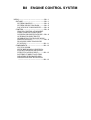
ENGINE CONTROL SYSTEM
3SZ,K3 ------------------------------------ B81
OUTLINE------------------------------- B81
SYSTEM DRAWING ---------------- B82
SYSTEM WIRING DIAGRAM ------- B85
LOCATION OF COMPONENTS----- B88
CONTROL ----------------------------- B89
IDLE-UP CONTROL AT MOMENT
WHEN VEHICLE STARTS MOVING(EUROPE SPECIFICATIONS) -- B89
ALTERNATOR ELECTRICITY
GENERATION CONTROL(EUROPE
SPECIFICATIONS)------------------ B89
DIAGNOSIS (SELF-DIAGNOSIS)
FUNCTION ----------------------- B811
COMPONENTS ---------------------- B813
CLUTCH UPPER
SWITCH(EUROPEAN SPECIFICATION M/T VEHICLES MOUNTED
WITH TYPE 3SZ ENGINES) ------ B813
BATTERY CURRENT AND TEMPERATURE INTEGRATED SENSOR(EUROPE SPECIFICATIONS)
----------------------------------- B813
B8-1
3SZ,K3
1 OUTLINE
Refer to TERIOS TECHNICAL INFORMATION
1. With the adoption of idle-up control at the moment when the vehicle starts moving, the following
changes have been made.(Europe specifications)
(1) A clutch upper switch has been added. (M/T vehicles mounted with type 3SZ engines)
2. With the adoption of alternator electricity generation control, the following changes have been
made.(Europe specifications)
(1) An integrated battery current and temperature sensor has been added.
(2) Some diagnosis (self-diagnosis) function specifications have been added.
(3) Some fail-safe function specifications have been added.
3. With the adoption of cylinder identification in the primary ignition system, the following changes have
been made. (General export specifications)
(1) Some diagnosis (self-diagnosis) function specifications have been added.
B8-2
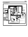
1-1 SYSTEM DRAWING
Europe specifications
Starter
Intake air
temperature sensor
Fuel pump
motor
CAN communication
Each relay
Shift range
information signal
(A/T vehicle)
Air cleaner
Radiator fan
motor
A/T
ECU
Compressor
magnet clutch
Shift position switch
(A/T vehicle)
Stop lamp switch
Battery current
and temperature Canister check
integrated sensor valve
Engine control computer
Vehicle speed
signal
VSC ECU
OR
Meter ECU
Fuel tank
Charcoal canister
Alternator
Throttle
position
sensor
VSV for evaporative
emission control
system purge control
Oil control
valve
PCV
valve
*1
Ignition coil
*2
Clutch upper switch
(M/T vehicle)
Manifold
absolute
pressure
sensor
Cam
angle
sensor
Fuel pump OFF demand signal
Valve for ISC
Surge
tank
Injector
Airbag ECU
EFI-Tterminal signal
DLC
Oxygen sensor
(with heater )
Variable valve timing
controller
Three-way
catalyst
Knock sensor
Water temperature sensor
Rear oxygen sensor
(with heater )
Engine revolution
sensor
J13E1502ES35
*1: Ion current detection device built-in
*2: M/T vehicles mounted with type 3SZ engines
B8-3
China specifications
Starter
Intake air
temperature sensor
Fuel pump
motor
CAN communication
Each relay
Shift range
information signal
(A/T vehicle)
Air cleaner
Radiator fan
motor
A/T
ECU
Compressor
magnet clutch
Shift position switch
(A/T vehicle)
Canister check
valve
Engine control computer
Vehicle speed
signal
VSC ECU
OR
Meter ECU
Fuel tank
Charcoal canister
Alternator
Throttle
position
sensor
VSV for evaporative
emission control
system purge control
Oil control
valve
PCV
valve
*1
Ignition coil
Manifold
absolute
pressure
sensor
Cam
angle
sensor
Fuel pump OFF demand signal
Valve for ISC
Surge
tank
Injector
Airbag ECU
EFI-Tterminal signal
DLC
Oxygen sensor
(with heater )
Variable valve timing
controller
Three-way
catalyst
Knock sensor
Water temperature sensor
Rear oxygen sensor
(with heater )
Engine revolution
sensor
J13E1508ES35
*1: Ion current detection device built-in
B8-4
General specifications
Starter
Intake air
temperature sensor
Fuel pump
motor
CAN communication
Each relay
Shift range
information signal
(A/T vehicle)
Air cleaner
Radiator fan
motor
A/T
ECU
Compressor
magnet clutch
Shift position switch
(A/T vehicle)
Canister check
valve
Engine control computer
Vehicle speed
signal
VSC ECU
OR
Meter ECU
Fuel tank
Charcoal canister
Alternator
Throttle
position
sensor
VSV for evaporative
emission control
system purge control
Oil control
valve
PCV
valve
Manifold
absolute
pressure
sensor
Cam
angle
sensor
Ignition coil
Fuel pump OFF demand signal
Valve for ISC
Surge
tank
Injector
Airbag ECU
EFI-Tterminal signal
DLC
Oxygen sensor
(with heater )
Variable valve timing
controller
Three-way
catalyst
Knock sensor
Water temperature sensor
Rear oxygen sensor
*1
Engine revolution
sensor
J13E1509ES35
*1:Rear oxygen sensor equipped vehicle
B8-5
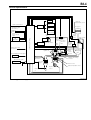
1-2 SYSTEM WIRING DIAGRAM
Engine
earth
Battery
Starter
STSW
Refer to the wiring
diagram for the details
of the air conditioner
illumination.
3
43
42
11
44
46
117
40
STP
DEF
BLW ACSW
A/T
FPOF
HGS2
DLC
41
113
E
C
U
-+
57
52
122
12
E
P
S
118
116
45
Evaporator temperature sensor
64 129
20 125
109
Outside air temperature sensor
Battery current
and temperature
integrated sensor
55
Intake air temperature sensor
Throttle position sensor
Oxygen sensor heater
123 15
Rear oxygen sensor
To A
18 14 19
56
53
54
Water temperature sensor
Oxygen sensor heater
121
Front oxygen sensor
To A
EFI T
REV
127
Knock sensor
58
PIM
VCPM
E2PM EPS
ACEV
E21
OUTTP
E1
E01
Manifold absolute pressure sensor
Cam angle sensor
128
STSW
107
ST
7.5A
107
Starter
M/T
vehicles
F/L
AM2
A/T
vehicles
ST
7.5A
Starter relay
E
C
U
A
/
T
63
Engine
10A
Ignition coil 1
CM
BATTP
39
27
38
48
49 60
61
51 62
50
Ignition coil 2
IG4
BAT
MRO
IG2
IG3
ICMB1 ICMB2 ICMB3 ICMB4 'B
To spark plug
IG1
A
EFI
15A
Main relay
Ignition coil 4
Engine control computer
W
23
24
28
M
F/P motor
Ignition coil 3
ACC
IG1
IG2
ST
ALT
ALTC
13
65
ISC
21
22
16
#
4
#
3
#
2
#
1
Injector
FC2 #10 #20 #30 #40 PRG
For evaporative purge VSV
N1(
N2(
THW
OXH1 OXH2
VC
N1'
N2'
KNK OX1
OX2
E2
VTH
THA
37
25
26
120
ECU IG2
7.5A
Engine check lamp
Valve for ISC
IG switch
OCV'
FAN1
IGSW
OCV(
M
Radiator fan
30A
Radiator fan relay
Oil control valve
AM1
Clutch upper switch(M/T vehicles)
Radiator fan motor
F/P relay
Immobilizer ECU
H/L
Magnet clutch relay
Wiper switch
59
IG1/
BACK
7.5A
36
MGC
10A
Compressor
magnet clutch
9
(CAN communication)
Airbag ECU
SIO2
4
6
8
7
(CAN communication)
HCAN
CANH
ATNE
LCAN
CANL
A/T
ECU
Alternator
MGC
135 134
Europe specifications
Engine revolution sensor
J13E5501ES45
B8-6
STSW
ST
7.5A
A/T
vehicles
Engine
earth
Body
earth
Battery
Starter
STSW
ST
7.5A
107
Starter
M/T
vehicles
F/L
AM2
IG switch
AM1
107
ACC
IG1
IG2
ST
Starter relay
E
C
U
A
/
T
63
Refer to the wiring diagram for
the details of the air conditioner illumination.
3
42
BLW ACSW
40
44
117
124
DLC
116
113
118
REV
EFI T
E21
45
ACEV
-+
To A
Oxygen sensor heater
Oxygen sensor heater
Front oxygen sensor
To A
THG
129
20 125
122
52
57
55
54
53
56
18 14 19
Throttle position sensor
Rear oxygen sensor
123 15
Engine
10A
Ignition coil 1
Water temperature sensor
121
51 62
50
Ignition coil 2
Intake air temperature sensor
Knock sensor
127
61
Ignition coil 3
Manifold absolute pressure sensor
58
39
27
38
49 60
48
To spark plug
IG1
A
EFI
15A
Main relay
Ignition coil 4
IG2
IG3
IG4
BAT
MRO
ICMB1 ICMB2 ICMB3 ICMB4 'B
F/P motor
F/P relay
Cam angle sensor
128
M
34
Injector
Outside air temperature sensor
59
24
#1
PIM
E1
VCPM
E2PM E01
23
#2
VTH
THA
THW
22
#3
Immobilizer ECU
Evaporator temperature sensor
VC
W
21
#4
Engine control computer
13
65
16
For evaporative purge VSV
FAN2 #10 #20 #30 #40 PRG
ISC
Engine check lamp
Valve for ISC
Airbag ECU
Power steering oil pressure switch
N2(
OXH1 OXH2
N1(
E2
N1'
OX2
N2'
KNK OX1
37
25
26
ECU IG2
7.5A
120
Oil control valve
OCV'
FAN1
IGSW
OCV(
Radiator fan
30A
M
Radiator fan motor
Radiator fan relay
43
11
DEF
STP
A/T
FPOF
SIO2
PST
Magnet clutch relay
ALT
135
4
6
7
8
36
IG1/
BACK
7.5A
MGC
10A
Compressor
magnet clutch
9
(CAN communication)
HCAN
CANH
ATNE
CANL
LCAN
A/T
ECU
(CAN communication)
MGC
Alternator
China specifications
Engine revolution sensor
J13E5513ES45
B8-7
Engine
earth
Refer to the wiring diagram for
the details of the air conditioner
illumination.
3
42
BLW ACSW
40
44
117
124
43
11
DEF
STP
A/T
FPOF
SIO2
PST
DLC
113
118
REV
116
45
129
20 125
-+
122
52
THG
E1
E01
PIM
E2PM
VCPM
57
ACEV
E21
Manifold absolute pressure sensor
55
THA
56
53
54
Water temperature sensor
19
Oxygen sensor heater
To A
18
123 15
Rear oxygen sensor
121
Front oxygen sensor
58
127
Knock sensor
128
Cam angle sensor
59
STSW
STSW
107
ST
7.5A
Body
earth
Starter
Battery
Engine control computer
VC
63
107
ST
7.5A
A/T
vehicles
Starter
M/T
vehicles
F/L
AM2
E
C
U
A
/
T
ACC
IG1
IG2
ST
IG1
Engine
10A
Ignition coil 1
Starter relay
Outside air temperature sensor
Throttle position sensor
Ignition coil 2
N2(
OXH1
E2
N1(
N1'
OX2
N2'
KNK OX1
61
IG3
62
IG2
Ignition coil 3
Evaporator temperature sensor
Intake air temperature sensor
VTH THW
39
27
38
BAT
60
Ignition coil 4
IG4
To spark plug
Main relay
MRO
'B
F/P motor
A
EFI
15A
W
13
22
23
24
35
M
F/P relay
ISC
65
16
21
#
4
#
3
#
2
#
1
Injector
FC1 #10 #20 #30 #40 PRG
For evaporative purge VSV
IG switch
Immobilizer ECU
Engine check lamp
Valve for ISC
AM1
Airbag ECU
Power steering oil pressure switch
EFI T
37
25
26
ECU IG2
7.5A
120
Oil control valve
ALT
135
M
Radiator fan
30A
Radiator fan relay
ATNE
4
6
7
8
9
36
Compressor
magnet clutch
MGC
10A
IG1/
BACK
7.5A
Magnet clutch relay
Radiator fan motor
HCAN
CANH
LCAN
CANL
(CAN communication)
MGC
A/T
ECU
(CAN communication)
OCV'
FAN1
IGSW
OCV(
Alternator
General specifications
Engine revolution sensor
J13E5512ES45
B8-8
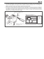
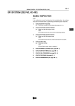
1-3 LOCATION OF COMPONENTS
s
l
q
k
t
c
j
p
r
n
v
a
u
b
h
w
i
d
g
m
f
e
o
J13E1501S30
Code
Part name
Code
a
Fuel pump
m*1
b
Engine control computer
n
c
Relay block
o
d
Cam angle sensor
p
e
Injectors
q
f
Knock sensor
r
g
Front oxygen sensor
s
h
Rear oxygen sensor
t
i
Engine coolant temperature sensor
u*2
j
Rotary ISC
v*3
k
Throttle position sensor
w*4
l
Manifold absolute pressure sensor
*1:Ion current detection device built-in for Europe and China specifications
*2:Automatic transaxle vehicles
*3:Europe specifications
*4:European specification (M/T vehicles mounted with type 3SZ engines)
Part name
Ignition coil
Oil control valve
Engine revolution speed sensor
VSV control for evaporative purge
DLC
Intake air temperature sensor
Combination meter
Fuse block
A/T ECU
Battery current and temperature integrated sensor
Clutch upper switch
B8-9
2 CONTROL
2-1 IDLE-UP CONTROL AT MOMENT WHEN VEHICLE STARTS MOVING(EUROPE
SPECIFICATIONS)
2-1-1 DESCRIPTION
1. When the vehicle starts moving with the shift lever in range, the engine control computer increases the idling speed of the engine to increase the creep power. (A/T vehicles)
2. When the clutch pedal is depressed, the engine control computer increases the idling speed of the
engine, making it easier for the vehicle to start moving. (M/T vehicles mounted with type 3SZ engines)
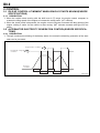
2-2 ALTERNATOR ELECTRICITY GENERATION CONTROL(EUROPE SPECIFICATIONS)
2-2-1 DESCRIPTION
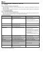
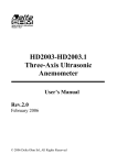
1. Through continuous monitoring of the battery status, the excessive electricity generation of the alternator can be prevented.
Regenerative condition
Restrained charging
condition
Running
condition
Acceleration
Deceleration
Stationary
Deceleration
Acceleration
J13E1005ES16
B8-10
2. The battery temperature sensor determines the temperature of the battery fluid surrounding the battery and sends signals to the engine control computer to perform charging control. Accordingly, the
battery is protected, and a drop in battery capacity can be prevented.
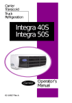
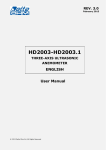
3. The Hall IC is used to detect the amount of current discharged. It converts the amount of change in
the magnetic flux density, which is generated at the core by the current discharged from the battery,
into voltage. The engine control computer receives this voltage as a signal, and calculates the battery
capacity from the change in the signal voltage.
Battery discharging current
Hall IC
Battery current and temperature
integrated sensor diagram
VC
VDD
Battery
current
sensor
Vout
CM
Engine
control
computer
BATP
GND
Battery
temperature
sensor
E2
Battery current and temperature
integrated sensor
Engine control computer
J13E1504ES16
B8-11
2-3 DIAGNOSIS (SELF-DIAGNOSIS) FUNCTION
2-3-1 OUTLINE
Refer to TERIOS TECHNICAL INFORMATION
1. With the addition of alternator electricity generation control, a diagnosis (self-diagnosis) function has
also been added.
2. With the adoption of cylinder identification in the primary ignition system,a diagnosis (self-diagnosis)
function has been added.
2-3-2 FAIL-SAFE FUNCTION
Refer to TERIOS TECHNICAL INFORMATION
1. When the malfunction is remedied to the normal condition after an abnormality was detected, the failsafe control will be released. However, the diagnosis result remains.
Fail-safe specifications
Item
Camshaft angle sensor system
Ignition primary system*1
Knock sensor system
Rear oxygen sensor system*2
Manifold absolute pressure sensor signal system
Throttle position sensor signal
system
Water temperature sensor signal
system
Intake air temperature sensor
signal system
Air conditioner evaporator temperature sensor signal system
Variable valve timing system
Rotary ISC system
Oil control valve system
Fail-safe execution conditions
When an abnormality occurs in the signal
from the camshaft angle sensor
When malfunction takes place in the ignition
signal
When abnormality takes place in the signal
from the knock sensor circuit
When malfunction takes place in the signal
from the rear oxygen sensor
When abnormality takes place in the signal
from the manifold absolute pressure sensor
When malfunction takes place in the signal
from the throttle position sensor
When malfunction takes place in the signal
from the water temperature sensor
When malfunction takes place in the signal
from the intake air temperature sensor
When malfunction takes place in the signal
from the A/C evaporator temperature sensor
When an abnormality occurs in the valve timing control twice in a row
When an abnormal signal occurs in the for
ISC
When malfunction takes place in the control
voltage for the oil control valve
*1:General specifications
*2:Rear oxygen sensor equipped vehicles
Fail-safe specifications
The signal from the camshaft angle sensor
is set to a constant value.
Fuel injection is stopped.
The fuel to each cylinder is cut.
Air-to-fuel ratio feedback control is prohibited.
The target displacement angle is kept constant.
The ignition timing is retarded.
The feedback control is turned to open control.
The manifold absolute pressure is estimated by the throttle opening angle and the
engine revolution speed.
When abnormality occurs in the signal from
the throttle position sensor, the signal from
the manifold absolute pressure sensor is set
to the constant value.
If both the throttle opening angle and engine speed exceed their set values, the fuel
is cut.
The signal from the throttle position sensor
is set to a constant value.
The signal from the water temperature sensor is set to a constant value.
The signal from the intake air temperature
sensor is set to a constant value.
The air conditioner will be cut.
The variable valve timing is set to the most
retarded timing angle.
Cut off the energizing control for ISC.
Prohibit the oil control valve energizing control.
B8-12
Item
Ion current control system*1*2
Battery current sensor signal
system*1
Battery temperature sensor signal system*1
Starter relay drive output system
Immobilizer signal circuit malfunction*3
CAN communication system
*1:Europe specifications
*2:China specifications
*3:Immobilizer equipped vehicles
Fail-safe execution conditions
When an abnormality occurs in the ion current
detection signal
When an abnormality occurs in the signal
from the integrated battery current and temperature sensor
When an abnormality occurs in the signal
from the integrated battery current and temperature sensor
When an abnormality occurs in the starter
relay output circuit or starter relay output
monitor circuit
Fail-safe specifications
Ignition timing retarding control using ion
current control is prohibited.
Alternator electricity generation control is
prohibited.
Alternator electricity generation control is
prohibited.
Starter relay control is prohibited.
Fuel cut control is implemented. (When the
engine revolution speed is 3500 rpm or
more)
Prohibition of fuel injection at moment
when vehicle starts moving
Prohibition of fuel injection and ignition.
When abnormality occurs in the writing and
reading-out of the rolling codes into/from the
immobilizer ECU during immobilizer communication.
When the rolling codes can not be exchanged
between the EFI ECU and immobilizer ECU
or rolling codes are not matched.
When an abnormality occurs in the CAN
The values used for control are kept concommunication system
stant.
B8-13
3 COMPONENTS
3-1 CLUTCH UPPER SWITCH(EUROPEAN
SPECIFICATION M/T VEHICLES MOUNTED
WITH TYPE 3SZ ENGINES)
Pedal bracket
The clutch upper switch is installed in the return stopper bolt
of the pedal bracket, and inputs the "ON" and "OFF" signals
of the clutch into the engine control computer.
Clutch upper
switch
J13E1003ET16
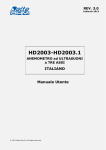
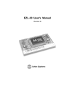
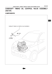
3-2 BATTERY CURRENT AND TEMPERATURE INTEGRATED SENSOR(EUROPE
SPECIFICATIONS)
The battery current and temperature integrated sensor is located on the side of the negative terminal of
the battery, where it is less likely to be affected by the heat of the engine, and detects both the charging
status and the temperature status of the battery.
Output
voltage
(V)
CM
E2
(()
BATP
VC
Current (A)
(')
A
View A
J13E1503ES16