1
When using this document, keep the following in mind:
nti
al
General Notice
1. This document is confidential. By accepting this document you acknowledge that you are bound
by the terms set forth in the non-disclosure and confidentiality agreement signed separately and /in
the possession of SEGA. If you have not signed such a non-disclosure agreement, please contact
SEGA immediately and return this document to SEGA.
de
2. This document may include technical inaccuracies or typographical errors. Changes are periodically made to the information herein; these changes will be incorporated in new versions of the
document. SEGA may make improvements and/or changes in the product(s) and/or the
program(s) described in this document at any time.
nfi
3. No one is permitted to reproduce or duplicate, in any form, the whole or part of this document
without SEGA’S written permission. Request for copies of this document and for technical
information about SEGA products must be made to your authorized SEGA Technical Services
representative.
4. No license is granted by implication or otherwise under any patents, copyrights, trademarks, or
other intellectual property rights of SEGA Enterprises, Ltd., SEGA of America, Inc., or any third
party.
Co
5. Software, circuitry, and other examples described herein are meant merely to indicate the characteristics and performance of SEGA’s products. SEGA assumes no responsibility for any intellectual
property claims or other problems that may result from applications based on the examples
describe herein.
GA
6. It is possible that this document may contain reference to, or information about, SEGA products
(development hardware/software) or services that are not provided in countries other than Japan.
Such references/information must not be construed to mean that SEGA intends to provide such
SEGA products or services in countries other than Japan. Any reference of a SEGA licensed product/program in this document is not intended to state or simply that you can use only SEGA’s
licensed products/programs. Any functionally equivalent hardware/software can be used instead.
7. SEGA will not be held responsible for any damage to the user that may result from accidents or any
other reasons during operation of the user’s equipment, or programs according to this document.
SE
NOTE: A reader's comment/correction form is provided with this
document. Please address comments to :
SEGA of America, Inc., Developer Technical Support (att. Evelyn Merritt)
150 Shoreline Drive, Redwood City, CA 94065
SEGA may use or distribute whatever information you supply in any way
it believes appropriate without incurring any obligation to you.
(11/2/94- 002)
SE
GA
Co
nfi
de
nti
al
TM
The SATURN
SCU DSP Simulator
User's Manual
Addendum
Doc. # ST-240-B-SP1-052295
© 1994-95 SEGA. All Rights Reserved.
nti
al
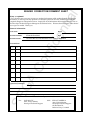
READER CORRECTION/COMMENT SHEET
Keep us updated!
If you should come across any incorrect or outdated information while reading through the attached
document, or come up with any questions or comments, please let us know so that we can make the
required changes in subsequent revisions. Simply fill out all information below and return this form to
the Developer Technical Support Manager at the address below. Please make more copies of this form if
more space is needed. Thank you.
General Information:
Phone
de
Your Name
Document number
ST-240-B-SP1-052295
Document name
The SATURN SCU DSP Simulator User's Manual Addendum
Date
Corrections:
Correction
nfi
pg. #
GA
Co
Chpt.
SE
Questions/comments:
Fax:
Where to send your corrections:
(415) 802-1717
Attn: Evelyn Merritt,
Developer Technical Support
Mail:
SEGA OF AMERICA
Attn: Evelyn Merritt,
Developer Technical Support
150 Shoreline Dr.
Redwood City, CA 94065
nti
al
The SATURN SCU DSP Simulator
User's Manual Addendum
by Dennis Caswell
5/17/95
Introduction
de
The DSP simulator (dspsim.exe) is a simple, command-line-oriented software emulator which makes
it possible to load, execute, and debug programs written for the DSP that is a part of the SATURN
System Control Unit (SCU).
Types of Memory Supported by the Simulator
nfi
The DSP simulator emulates the two types of memory found within the DSP itself (program RAM
and the four banks of data RAM), and it also simulates a 256-megabyte external memory space,
which can be used as a source or destination for DMA transfers performed by a DSP program. It is
not clear how this simulated memory is actually implemented or what would happen if you tried to
use all of it.
Co
Addresses in the DSP’s internal memory are 32-bit-word-addresses, while addresses in external
memory are byte addresses. Nonetheless, the simulator will only access external memory in 32-bit
chunks that are aligned on 32-bit boundaries, so all external memory addresses used in commands to
the simulator should be divisible by 4.
Command Summary
GA
Mini-assembler
Breakpoints
Dump memory
Enter one or more values into memory
Fill a range of memory with a specified value
Go
Execution history
Load a binary or S-record file
Move memory
Set program memory size
Quit
Display and set registers
Single step
Disassemble (unassemble)
Write a binary or S-record file
Command history
Repeat last command
Repeat specified command
Display on-line command summary
SE
A
B
D
E
F
G
H
L
M
P
Q
R
S
U
W
^
!!
!
?
The SATURN SCU DSP Simulator
User's Manual Addendum
1
Command Descriptions
nti
al
A [<prog addr>]
Activate the mini-assembler, storing instructions starting at the specified address. The assembler
accepts all DSP mnemonics, but it does not accept labels, assembler directives, or expressions.
Exit the mini-assembler by entering a blank line.
B <prog addr>, B, B-, BX [<n>]
D [[<ram>] [<addr1> [<addr2>]]]
de
B <prog addr> sets an execution breakpoint at the specified address in program memory.
B lists all current breakpoints.
B- deletes all breakpoints.
BX [<n>] deletes the breakpoint that occupies the specified position in the list of breakpoints. If the
parameter is omitted, BX is the same as B-.
E [<ram>] <addr1> [<value>]
nfi
Dump memory from <addr1> through <addr2>. The <ram> parameter specifies the type of
memory to be dumped. Substitute p for program RAM, m for external RAM, or r0, r1, r2, or r3
for one of the DSP’s four banks of data RAM. If <ram> is omitted, it defaults to the most-recentlyreferenced memory area. If <addr2> is omitted, it defaults to <addr1> + 0x3f for program or data
memory and <addr1> + 0xff for external memory. If all of the parameters are omitted, the next 64
32-bit words are displayed.
Store the value to the current address and go to the next address.
Go to the next address without altering the contents of the current address.
Back up to the previous address without altering the contents of the current address.
Exit the data-entry mode and return to the simulator’s main command prompt.
Same as @.
GA
<value>
@
^
.
<enter>
Co
Enter one or more 32-bit numbers into memory. The <ram> parameter specifies the type of memory
to use. Substitute p for program RAM, m for external RAM, or r0, r1, r2, or r3 for one of the DSP’s
four banks of data RAM. If <ram> is omitted, it defaults to the most-recently-referenced memory
area. If <value> is omitted, then the simulator enters a command mode in which a series of values
may be entered into consecutive memory addresses. When in this mode, the simulator prompts with
an address and accepts one of the following commands:
F [<ram>] <addr1> <addr2> <value>
SE
Fill a range of memory with a single 32-bit value. The <ram> parameter specifies the type of memory
to be filled. Substitute p for program RAM, m for external RAM, or r0, r1, r2, or r3 for one of
the DSP’s four banks of data RAM. If <ram> is omitted, it defaults to the most-recently-referenced
memory area.
G [<prog addr1> [<prog addr2>]
Start executing instructions at the specified address in program memory. If a second address is
specified, execution terminates at that address.
2
H [<n>], H+, H-, H@
nti
al
H [<n>] displays a history of register values extending back for the specified number of instructions. The default is 10.
H+ enables the history mechanism (the default).
H- disables the history mechanism.
H@ clears the history buffer.
L <ram> <file> <addr>
de
Load a binary or S-record file. File names having the extensions “.s” or “.mot” are presumed to be Srecord files. Files having other extensions are presumed to be binary files. The <ram> parameter
specifies the type of memory to be loaded. Substitute p for program RAM, m for external RAM, or
r0, r1, r2, or r3 for one of the DSP’s four banks of data RAM. When loading an S-record file,
the <addr> parameter is added to the addresses contained in the S-record file.
M <ram1> <addr1> <addr2> [<ram2>] <addr3>
nfi
Move a range of memory to the specified address. The <ram1> and <ram2> parameters specify the
types of memory to be read and written. Substitute p for program RAM, m for external RAM, or r0,
r1, r2, or r3 for one of the DSP’s four banks of data RAM. If <ram2> is omitted, it defaults to
<ram1>. Overlapping source and destination ranges are handled correctly.
P, PE, PR
Co
P displays current program size setting.
PE sets size of simulated program memory to 2048 32-bit words.
PR sets size of program memory to 256 32-bit words (the default).
Q
Quit to DOS (no confirmation).
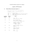
R, R@, R {<reg>|<flag>} <value>
GA
R display the contents of all of the registers and processor flags.
R@ sets all registers and flags to zero.
R {<reg>|<flag>} <value> sets the specified register or processor flag to the specified value. To
set one of the registers, substitute one of the following for the <reg> parameter: PC, TP, LP,
CT0, CT1, CT2, CT3, TN, RA, WA, RX, RY, PH, PL, ACH, or ACL. The following table
shows how to specify the various processor flags, along with the symbol used to label each flag in the
simulator’s register display.
SE
Specified as Labeled as Definition
Specified as Labeled as Definition
PR
P
Pause reset
V
V
Overflow
EP
e
Execute pause
E
E
End interrupt
T0
T
Transfer 0 (D0 DMA flag)
ES
s
Execute step
S
S
Sign
EX
x
Execution control
Z
Z
Zero
LE
L
PC load enable
C
C
Carry
The SATURN SCU DSP Simulator
User's Manual Addendum
3
S [<n>]
Execute the specified number of instructions (the default is 1).
U [<prog addr1> [<prog addr2>]]
nti
al
Note that version 2.11 of the simulator contains a bug in the implementation of the V flag (see Bugs,
below).
V, VM, VS
W <ram> <addr1> <addr2> <file>
nfi
V displays current emulation mode (Model M or Model S).
VM sets midbox (Model M) emulation mode.
VS sets small box (Model S) emulation mode (the default).
de
Disassemble (unassemble) the specified range of program memory. If <prog addr2> is omitted, it
defaults to <prog addr1> + 0xf. The disassembled data is formatted so that the so-called “Operation Commands” (instructions controlling the ALU, the X-bus, the Y-bus, and the D1-bus) are aligned
in columns according to which subcomponent of the DSP they use. This makes it easier to see which
subcomponents are idle at any given time, which in turn makes it easier to increase parallelism.
Co
Write the specified range of memory to a binary or S-record file. File names having the extensions
“.s” or “.mot” will be written as S-record files. Files having other extensions will be written as binary
files. The <ram> parameter specifies the type of memory to be written. Substitute p for program
RAM, m for external RAM, or r0, r1, r2, or r3 for one of the DSP’s four banks of data RAM. The
S-record files produced by this command are UNIX-flavored, i.e. they contain no carriage returns,
only linefeeds, so you may wish to convert them with a utility such as unix2dos.exe.
^ [<n>]
Display the last n entries in the command history (default is 20). The command history buffer holds
the most recent 50 commands.
GA
!!
Repeat the last command.
! <n>
Repeat the nth command in the command history.
?
SE
Display an on-line command summary.
<enter>
If the last command was S, D, or U (with or without parameters), then pressing <enter> is equivalent to typing S, D, or U without parameters, i.e. it executes the next instruction, or it dumps or
disassembles the next chunk of memory. Otherwise, it does nothing.
4
Notes
nti
al
Memory addresses and values to be stored in memory must be expressed in hexadecimal. Other
numerical parameters must be expressed in decimal.
Any address parameter may be appended with the letter L, which causes it to be multiplied by four.
This is intended as a convenience in addressing external memory. For example, to move the second
32-bit word (word 1) of program memory to the third 32-bit word (bytes 8 through 11) of external
memory, you could say either M P 1 1 M 8 or M P 1 1 M 2L. For what it’s worth, this notation
can be used with memory data parameters as well.
Commands and parameters may be typed in either upper or lower case.
de
You can create a batch file of simulator commands that will be executed when the simulator is
launched. Create a text file containing one simulator command per line, then invoke the simulator
with a command of the form dspsim batchfil.
Bugs
SE
GA
Co
nfi
Version 2.11 of the simulator contains a bug in the implementation of the V flag, which is used to
detect signed arithmetic overflows caused by the ADD, AD2, and SUB instructions. In the actual
DSP, the V flag is set when addition or subtraction results in a signed arithmetic overflow (e.g. adding
two positive numbers and getting a negative result). If there is no overflow, the V flag is cleared. In
the simulator, the V flag is set whenever the C flag is set as a result of addition or subtraction, and it is
never cleared. To clear it, you must issue the command r v 0.
The SATURN SCU DSP Simulator
User's Manual Addendum
5