1
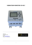
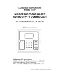
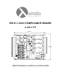
EN 81.1-2/A3 COMPLIANCE BOARD
L-A3-1 V1
L1
90 mm
RLY-4
LD7
K2
IC1A
D1
C1
K1
C2
IC1
RLY-3
LD8
C4
C5
BR1
F1
RLY-2
LD9
C6
80 mm
L2
RLY-1
LD10
L-A3-1
LD11
C7
IC7
SW1
X1
LAMDA Inc.
LD12
RST
HUD
JP8
J1
2T
USER’S MANUAL & INSTALLATION GUIDE
USER’S MANUAL
2
LAMDA ELECTRONICS S.A.
INNOVATION THAT LIFTS YOU USER’S MANUAL
Copyright
© 2011 Lamda Electronics. All Rights Reserved.
This document may not be reproduced, electronically or mechanically, in whole or in
part, without written permission from Lamda Electronics.
Warning and Disclaimer
Although every effort has been made to make this document as complete and
accurate as possible, Lamda Electronics and the document authors, publishers, distributors,
and representatives have neither liability nor responsibility for any loss or damage arising
from information contained in this document or from informational errors or omissions.
Information contained in this document shall not be deemed to constitute a commitment to
provide service, equipment, or software by Lamda Electronics or the document authors,
publishers, distributors, or representatives.
Limited Warranty
Lamda Electronics (manufacturer) warrants its products for a period of 24 months
from the date of shipment from its factory to be free from defects in workmanship and
materials. Any defect appearing more than 24 months from the date of shipment from the
factory shall be deemed to be due to ordinary wear and tear. Manufacturer, however,
assumes no risk or liability for results of the use of the products purchased from it, including,
but without limiting the generality of the forgoing: (1) The use in combination with any
electrical or electronic components, circuits, systems, assemblies or any other material or
equipment (2) Unsuitability of this product for use in any circuit, assembly or environment.
Purchasers’ rights under this warranty shall consist solely of requiring the manufacturer to
repair, or in manufacturer's sole discretion, replace free of charge, F.O.B. factory, any
defective items received at said factory within the said 24 months and determined by
manufacturer to be defective. The giving of or failure to give any advice or recommendation
by manufacturer shall not constitute any warranty by or impose any liability upon the
manufacturer. This warranty constitutes the sole and exclusive remedy of the purchaser and
the exclusive liability of the manufacturer, AND IN LIEU OF ANY AND ALL OTHER
WARRANTIES, EXPRESSED, IMPLIED, OR STATUTORY AS TO MERCHANTABILITY,
FITNESS, FOR PURPOSE SOLD, DESCRIPTION, QUALITY PRODUCTIVENESS OR ANY
OTHER MATTER. In no event will the manufacturer be liable for special or consequential
damages or for delay in performance of this warranty.
Products that are not manufactured by LAMDA ELECTRONICS are not covered
under the above warranty terms. LAMDA ELECTRONICS, however, extends the same
warranty terms that the original manufacturer of such equipment provide, with their product
(refer to the warranty terms for such products in their respective manual).
LAMDA ELECTRONICS S.A.
INNOVATION THAT LIFTS YOU 3
USER’S MANUAL
Table of contents
Table of contents .................................................................................................................... 4
SAFETY PRECAUTIONS ............................................................................................................. 5
Information on Safety ............................................................................................................ 5
Personnel’s Safety Precautions............................................................................................. 5
Product’s Safety Precautions ................................................................................................ 5
Symbols and Safety terms ...................................................................................................... 5
Technical Characteristics........................................................................................................... 6
Inputs ......................................................................................................................................... 7
Outputs ...................................................................................................................................... 7
Connection Diagrams ................................................................................................................ 8
Hydraulic Lift Connection Diagram.......................................................................................... 8
Traction Lift Connection Diagram ............................................................................................ 9
Tables – Figures Catalogue ................................................................................................ 10
Revision history..................................................................................................................... 10
LAMDA ELECTRONICS S.A.
INNOVATION THAT LIFTS YOU 4
USER’S MANUAL
SAFETY PRECAUTIONS
Information on Safety
Please, read this manual carefully, before you proceed to the installation of the
Control Cabinet, the cabling and the regular inspection of the cabinet. Keep this manual in a
safe place and available to all installation and engineering personnel during the operation of
the lift control cabinet.
The product that is described in this manual can be adjusted so that it can comply with the
international norms and EE derivatives. LAMDA ELECTRONICS shall take no responsibility if
the installation company does not adjust the product according to the current laws which are
effective in the country which the installation process is taking place.
Personnel’s Safety Precautions
Do not touch any of the electric, electrical or electronic part of the system which is
under voltage.
Before you start operating the lift control cabinet or a part of it, be sure that there are
no people close to you that could be hurt by the lift’s move or any part of it. All safety
components should be checked for their proper functionality. In any case, the lift should be in
the inspection position.
Product’s Safety Precautions
•
Do not plug or unplug electronic boards or electronic components under voltage.
•
Do not use a megometer when the electronic boards (PCBs) are plugged in.
Megometers operate under high voltage and can easily destroy the PCB’s
semiconductors.
Do not force the terminal blocks while you install them. They are designed for easy
use and installation. If you cannot install them easily, it’s probably because either you
try to install them up-side-down or they are not aligned.
Do not install the product near heating sources, vibrating sources or sources of high
humidity.
Check out and be sure about the grounding quality. All groundings should have star
type connections. Groundings of bad quality can cause interference in the proper
operation of the system.
Use proper material for packaging the entire product or parts of it.
•
•
•
•
Symbols and Safety terms
The symbols below might appear either on the product or in the installation manual.
DANGER
HIGH VOLTAGE
ATTENTION
NOTE
GROUNDING
Table 1
LAMDA ELECTRONICS S.A.
INNOVATION THAT LIFTS YOU 5
USER’S MANUAL
Technical Characteristics
L1
90 mm
RLY-4
LD7
K2
IC1A
D1
C1
K1
C2
IC1
RLY-3
LD8
C4
C5
6
BR1
F1
RLY-2
LD9
C6
80 mm
L2
RLY-1
LD10
L-A3-1
LD11
C7
IC7
SW1
X1
LAMDA Inc.
LD12
RST
HUD
JP8
J1
2T
Figure 1
The board dimensions are: 9Χ8 cm. The board has been designed with four
(4) holes near the edges for its installation using M3 spacers.
Power Supply
Units
CPU
Terminal Blocks
Operating
Voltage
24VDC
Operating
Current
150mA
Comments
Controller
Signals
IN1~/+ - IN1~/IN2~/+ - IN2~/IN3~/+ - IN3~/IN4~/+ - IN4~/IN5~/+ - IN5~/-
12 – 115 VDC / VAC
1.5mA
(24VDC)
Common or
ground 12 – RLY-1 COM - RLY-1 NC
RLY-2 COM - RLY-2 NC
RLY-3 COM- RLY-3 NC- RLY-3 NO
RLY-4 COM - RLY-4 NO
230V AC/DC
(220250VAC/DC)
+24VDC
GND
115 VDC / VAC (depending on the voltage used) Inputs
Outputs
RLY-1 ~ 4
-
12A /
250VAC
Power
Relays
Table 2
LAMDA ELECTRONICS S.A.
INNOVATION THAT LIFTS YOU USER’S MANUAL
Inputs
The Lamda A3 Compliance Board inputs are activated with signals of voltage 12 –
115 VDC / VAC. A description of the input block terminals is given in the following table.
Inputs
IN1~/+ - IN1~/IN2~/+ - IN2~/IN3~/+ - IN3~/IN4~/+ - IN4~/IN5~/+ - IN5~/-
Operation
Input from the safety circuit just before the landing doors
Input from the safety circuit just after the landing doors
Intended Car Movement Signal (Given by the Controller)
Direction Signal (Up or Down), (Given by the controller)
Zone Signal. Typically coming from a magnetic switch.
Table 3
7
Outputs
The board’s outputs are dry relay contacts. The description of their operation is given
in the table below.
Outputs
Operation
RLY-1
The normally closed contact (N.C.) of this relay is placed in-between the safety
circuit. Ideally just before the final limit switches. When an Unintended Car
Movement (UCM) is detected the relay will open the safety circuit.
The normally closed contact (N.C.) of this relay is placed in-between the signal
that activates the motor power relay. In the case of a traction lift it is placed inbetween the base block of the VVVF device. When an Unintended Car
Movement (UCM) is detected, while moving upwards, the relay will be activated.
This relay haw two contacts. One is Normally Open (NO) and one is Normally
Closed (NC). The NO contact is used in the case of a Hydraulic lift and activates
the A3 valve coil. The NC contact is used in the case of a Traction lift and its
purpose is to block the brake signal.
The normally open contact of this relay activates the overspeed governor.
RLY-2
RLY-3
RLY-4
Table 4
LAMDA ELECTRONICS S.A.
INNOVATION THAT LIFTS YOU /2.0
0
-S1
+
14
13
-
L-A3-1
GND +24VDC
Project
12 - 115 VDC / VAC
12
11
12
11
12
4
12
11
10
9
8
7
6
5
4
3
2
1
I N5 ~/-
I N 5 ~/+
I N4 ~/-
I N 4 ~/+
I N3 ~/-
I N 3 ~/+
I N2 ~/-
I N 2 ~/+
I N1 ~/-
I N 1 ~/+
GND
+24 V DC
K1
F1
SAFETY LINE BEFORE CAR DOORS
Pro ject template with IEC identifier stru cture
/2.3
ZONE MAGNETIC SWITCH
LOCKS
CAR DOORS
SAFETY LINE
11
B / 1.7
A / 1.7
EPLAN
DIRECTION SIGNAL COMMON
DIRECTION SIGNAL
INTENDED CAR MOVEMENT COMMON
INTENDED CAR MOVEMENT
SAFETY LINE COMMON
SAFETY LINE LINE END
SAFETY LINE START
3
C1
C5
C4
5
C6
HUD
JP8
2T
IC1
L1
C7
LD10
L2
LD9
BR1
LD8
LD7
/
VIN COM
J1
IC7
HYDRAULIC
A3 VALVE / VIN COM
OVERSPEED GOVERNOR
L AMD A Inc.
C2
2
D1
IC1A
1
6
RLY-4
RLY-3
RLY-2
LAMDA ELECTRONICS S.A.
X1
SW1
GND
RLY4-NO
RLY4-COM
RLY3-NO
RLY3-NC
RLY3-COM
RLY2-NC
RLY2-COM
RLY1-NC
RLY1-COM
K2
R ST
LD12
LD11
L -A3-1
RLY-1
CONTROL
PANEL
10
9
8
7
6
5
4
3
2
1
SAFETY LINE BEFORE CAR DOORS
8
9
-K1
Changed by
Creation date
-Y1
14/3/2012
OWNER
A2 Α3 VALVE
A1
Page
Page
Creator
Modification date
x2
x1
/
VIN
OVERSPEED
GOVERNOR
A3 VALVE
2
1
1 5/3/2012
FLAMOUROPOULOS
/
VIN
INTERVENES TO UP DIRECTION RELAY (POWER RELAY)
OVERSPEED
GOVERNOR
GND
/
/
A / 1.3
B / 1.3
7
USER’S MANUAL
Connection Diagrams
Hydraulic Lift Connection Diagram
8
Figure 2
INNOVATION THAT LIFTS YOU /2.0
0
-S1
/2.3
ZONE MAGNETIC SWITCH
LOCKS
CAR DOORS
SAFETY LINE
Project template with IEC identifier structure
EPLAN
INTENDED CAR MOVEMENT COMMON
INTENDED CAR MOVEMENT
SAFETY LINE COMMON
SAFETY LINE LINE END
SAFETY LINE START
2
+
14
13
-
12 - 115 VDC / VAC
12
11
12
11
12
11
A / 1.7
B / 1.7
3
Project
L-A3-1
GND +24VDC
12
11
10
9
8
7
6
5
4
3
2
1
IN5 ~/-
IN 5 ~/+
IN4 ~/-
IN 4 ~/+
IN3 ~/-
IN 3 ~/+
IN2 ~/-
IN 2 ~/+
IN1 ~/-
IN 1 ~/+
GND
+24 V DC
K1
F1
SAFETY LINE BEFORE CAR DOORS
4
C1
C5
C4
5
C6
HUD
JP8
2T
IC1
L1
C7
LD10
L2
LD9
BR1
LD8
LD7
/
VIN COM
J1
IC7
HYDRAULIC
A3 VALVE / VIN COM
OVERSPEED GOVERNOR
L AMD A I nc.
C2
D1
IC1A
1
6
RLY-4
RLY-3
RLY-2
LAMDA ELECTRONICS S.A.
X1
SW1
GND
RLY4-NO
RLY4-COM
RLY3-NO
RLY3-NC
RLY3-COM
RLY2-NC
RLY2-COM
RLY1-NC
RLY1-COM
K2
R ST
LD12
LD11
L-A3-1
RLY-1
CONTROL
PANEL
10
9
8
7
6
5
4
3
2
1
SAFETY LINE BEFORE CAR DOORS
8
9
-K1
Changed by
Creation date
A2
A1
Creator
Page
Page
M odification date
X
14/3/2012
x1
x2
-Y1
Α3 VALVE
/
VIN
OVERSPEED
GOVERNOR
A3 VALVE
1 9/3/2012
FLAMOUROPOULOS
1
2
/
VIN
INTERVENES TO UP DIRECTION RELAY (POWER RELAY)
OVERSPEED
GOVERNOR
GND
/
/
A / 1.3
B / 1.3
7
USER’S MANUAL
Traction Lift Connection Diagram
9
Figure 3 INNOVATION THAT LIFTS YOU USER’S MANUAL
Tables – Figures Catalogue
Figure 1 .................................................................................................................................... 6
Figure 2 .................................................................................................................................... 8
Figure 3 .................................................................................................................................... 9
10
Table 1...................................................................................................................................... 5
Table 2...................................................................................................................................... 6
Table 3...................................................................................................................................... 7
Table 4...................................................................................................................................... 7
Revision history
The revision dates and content of the revised manual appear on the following
table.
Date of publication
March 2012
LAMDA ELECTRONICS S.A.
Revision number
1
Revised content
First edition
INNOVATION THAT LIFTS YOU 4, Riga Fereou Str.
XANTHI – GREECE
EL. & FAX +(30)25410 – 78852
www.lamdaelectronics.com
E-mail: [email protected]