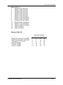
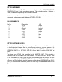
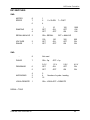
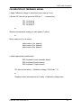
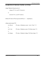
1
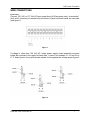
The MP SERIES CONTROLLER User’s Manual ISE, Inc. 10100 Royalton Rd. Cleveland, OH 44133 USA Tel: (440) 237-3200 Fax: (440) 237-1744 http://variac.com Form No, 003-1622 Rev G 02/25/2009 The MP Series Controller Form No. 003-1622 Rev G MP Series Controller CONTENTS INTRODUCTION ............................................................................................................. 6 General Description ..................................................................................................... 6 Model Number System ................................................................................................ 6 WIRE CONNECTIONS ................................................................................................... 7 Voltage Feedback Signals(s) ....................................................................................... 8 Motor Control ............................................................................................................... 9 Set Point Input ........................................................................................................... 10 Remote Signal ........................................................................................................... 10 High/Low Limits ......................................................................................................... 11 Set-Up Switches ........................................................................................................ 12 Motor Speed .............................................................................................................. 12 Ramping .................................................................................................................... 12 Serial\Analog ............................................................................................................. 12 Voltage Range ........................................................................................................... 12 Phase ........................................................................................................................ 13 Deadband .................................................................................................................. 13 Averaging .................................................................................................................. 13 Local/Remote ............................................................................................................ 13 Option S (Process Control Set Point) ........................................................................ 14 Option T(Microterminal).............................................................................................. 15 Display Signal (Voltage) ............................................................................................ 15 Display Set Point Target ............................................................................................ 15 Input New Target Set Point ........................................................................................ 15 Three Phase Operation ............................................................................................. 15 High/Low Limit Set Point ............................................................................................ 16 Form No. 003-1622 Rev G 1 MP Series Controller Option 2 (RS-232) ........................................................................................................ 17 <COMMAND><SUBCOMMAND><POSITION><SPACE><VALUE><ETX> ............. 17 Communications ........................................................................................................ 17 Pin Assignments ........................................................................................................ 17 Commands ................................................................................................................ 18 Subcommands ........................................................................................................... 18 Tables ........................................................................................................................ 18 Mode Table (M) ...................................................................................................... 18 Target Voltage Table (T) ........................................................................................ 18 Voltage Reading Table (V) ..................................................................................... 18 Alarm Table (L) ...................................................................................................... 19 EXAMPLES ............................................................................................................... 20 OPTION 4 (RS-422) ...................................................................................................... 21 PIN ASSIGNMENTS.................................................................................................. 21 OPTION L (Phase Loss) .............................................................................................. 21 DIP SWITCHES ............................................................................................................ 22 SW2: .......................................................................................................................... 22 SW3: .......................................................................................................................... 22 CALIBRATION OF FEEDBACK SIGNAL .................................................................... 23 CALIBRATION OF PROCESS CONTROL (S option) ................................................. 24 Form No. 003-1622 Rev G 2 MP Series Controller INTRODUCTION GENERAL DESCRIPTION The MP Series Voltage Controller is a microprocessor based controller designed for controlling motor driven variable transformers. The controller accepts set point and feedback voltage inputs and provides output signals until the feedback voltage matches the set point. The input set point signal may be any of many different forms of voltage, current or computer interface type signals. The feedback signal may be any of many voltage levels or frequencies. The output signals can be many types including form C type closures, digital or computer interface type signals. Input signals can be measured using peak, average or RMS techniques with software averaging. Output control can be simple increase/decrease signals. Multiple set points may be programmed using variable speed (time proportioning) ramping with variable dwell. MODEL NUMBER SYSTEM The model numbering system gives you information about your MP controller. The following list shows how to determine your controller's configuration from the model number. Model Function MPA Single channel feedback and control. MPB Two independent channels of control and feedback. MPC Three independent channels of control and feedback. Options Function T Microterminal mounted on front door of enclosure. S External process control set point. User configurable for 0-1 mA, 4-20 mA, 0-50 mVDC, or 0-10 VDC. I Isolated feedback signals and/or isolated process control signal. 2 RS-232C computer interface. 4 RS-422 computer interface for polled operation. 8 IEEE 488 interface. Form No. 003-1622 Rev G 6 MP Series Controller WIRE CONNECTIONS Input Power Connect 120, 240, or 277 Volt AC input power lines (#14 Awg wires max.) to terminals 1 (hot) and 2 (common) of terminal strip at bottom of panel mounted inside the controller (see figure 1). Figure 1 If voltage is other than 120 Volt AC, locate power supply board assembly mounted inside the controller in the upper left hand side. Locate 3 pin headers J3, J4, and J5 on P. C. board (next to fuse) and relocate shunts for the appropriate voltage as per figure 2. Figure 2 Form No. 003-1622 Rev G 7 MP Series Controller VOLTAGE FEEDBACK SIGNALS(S) Connect VOLTAGE FEEDBACK SIGNAL sense channels to terminal strip as follows (Figure 3 or 4): Sense channel Phase A to positions 4 and 6, and if three phase option is used, sense channel Phase B to positions 7 and 9 and sense channel Phase C to positions 10 and 12 (#14 Awg wires max.). The 5 pin connectors at J7 on main microcontroller board and if three phase option is used, connectors J8 and J9 on the lower microcontroller board must be configured based on the selected voltage feedback range (see DIP SWITCHES SW2-1 and 2). If the 150 or 300 voltage range is selected, the blue/white and black/white leads from the sense transformers must be configured for each transformer respectively (see figure 3). If the 150 voltage range is selected, place the 5 pin connectors to the left so that pin #1 of the connector matches up with pin #1 of the header on the board and pin #6 of the header on the board is not connected (see figure 3). If the 300 voltage range is selected, place the 5 pin connectors to the right one (1) position so that pin #1 of the connector matches up with pin #2 of the header on the board and pin #1 of the header on the board is not connected (see figure 3). Figure 3 If the 300 or 600 voltage range is selected, the blue/white and black/white leads from the sense transformers must be configured for each transformer respectively, the 5 pin connectors must be positioned as shown (see figure 4). Figure 4 Form No. 003-1622 Rev G 8 MP Series Controller MOTOR CONTROL The microcontroller is capable of controlling all STACO's motor driven autotransformers. Connect 120 Volt AC power to J2-1 on the microcontroller main printed circuit (PC) board, connect 120 Volt AC neutral to terminal C on the variable motor drive terminal strip, connect J2-2 on the microcontroller PC main board to terminal R on the variable motor drive terminal strip, and connect J2-3 on the microcontroller main PC board to terminal L on the variable motor drive terminal strip (see figure 5). If the THREE PHASE option is being used, connect 120 Volt AC power to J3-1 and J12-1 on the lower microcontroller lower PC board, connect 120 Volt AC neutral to terminal C on the phase B and C variable motor drive terminal strips, connect J3-2 on the microcontroller lower PC board to terminal R on the phase B variable motor drive terminal strip, connect J3-3 on the microcontroller lower PC board to terminal L on the phase B variable motor drive terminal strip, connect J12-2 on the microcontroller lower PC board to terminal R on the phase C variable motor drive terminal strip, and connect J12-3 on the microcontroller lower PC board to terminal L on the phase C variable motor drive terminal strip (see figure 5). Figure 5 Form No. 003-1622 Rev G 9 MP Series Controller SET POINT INPUT The microcontroller will accept set input from different sources. The basic unit is supplied with a potentiometer mounted to the enclosure back panel with the wiper connected to connector J1-7 on the main microcontroller PC board, counter clockwise end of the pot connected to J1-6, the clockwise end of the pot connected to J1-9 (see figure 6), and wing resistors R28 and R29 at 0 ohm. The operating set point also may be controlled using the following options: S - PROCESS CONTROL SET POINT T - MICROTERMINAL 2 - RS-232 4 - RS-422 8 - IEEE-488 Figure 6 REMOTE SIGNAL Low level logic signals (150 ma @ 5 VDC) for raise/lower control, high/low alarms and other functions are available at connector J4 on the main PC board and J5 and J6 on the option board (see fig. 7). Figure 7 Form No. 003-1622 Rev G 10 MP Series Controller HIGH/LOW LIMITS Microcontrollers with either T (microterminal) or 2,4, or 8 (serial interfaces - RS232, RS422 or IEEE) options have available a high and low limit for each phase. These limits will responds to the feedback signal(s) and user programmable limit set points. The output for these limits is a low level logic signal (150 MA @ 5VDC) which is available on P4 for phase A and P5 for phases B and C (see fig. 7). The limit signal level is "high" (+5VDC) if the limit is in a "safe" condition when the corresponding feedback signal is above the LOW LIMIT or below the HIGH LIMIT. The limit signal is low (0 VDC) if the limit is in a "tripped" condition when the feedback signal is (below the LOW LIMIT or above the HIGH LIMIT for longer than the Alarm On Delay(factory set at 0 seconds or user setable from 2,4, or 8 option table L). Once exceeded the limit(s) will remain in the "tripped" state until the corresponding feedback signal has returned to a "safe" level and the feedback signal is within the preset control deadband for a continuous Alarm Off Delay (factory set at 5 seconds or user setable from 2,4, or 8 option table L). Refer to OPTION T (microterminal - HIGH/LOW LIMITS) or OPTION 2 (RS-232 Alarm Table L) for setting set points. All of the HIGH/LOW LIMIT alarms may be monitored or reset with the OPTION 2 , 4 or 8 (ref. Alarm Table L). A set of MASTER LIMITs are also available on connector P4 (see fig. 7), one normally high (5 VDC = NH) and one normally low (0 VDC = NL). These signals are a summary of all the HIGH and LOW LIMIT alarms. The MASTER LIMITs change state when any of the HIGH or LOW LIMITS go from a safe condition to a tripped condition and return to normal when all tripped alarms are safe. Form No. 003-1622 Rev G 11 MP Series Controller SET-UP SWITCHES The microcontroller is capable of operating in several different operation modes with selectable control ranges. The selection of a particular operating mode or range is made by using miniature switch on the microprocessor printed circuit board. MOTOR SPEED The microcontroller using pulse width modulation causes the motor on the variable transformer to operate at two speeds (High - range 1 and Low - range 2). The motor is run in High speed when there is a large difference between the signal value and the set point (range 1). When there is a small difference between the signal value and the set point(range 2), the microcontroller will cause the motor to operate at a lower speed relative to the high speed. The SPEED switches, SW2-8, 7, and 6 determine the operating speed of the motor with FAST being full motor speed for high speed. The relationship between fast and slow is fixed. RAMPING The RAMPING switches, SW2-5, and 4 determine a multiplication factor for the times loaded in the ramping table (R). The microcontroller will multiply the time set in the ramping table by the number set by these switches (1, 10, 100, 1000). SERIAL\ANALOG The SERIAL\ANALOG switch, SW2-3 determines the source of the set point. Serial selection receives set point information from option T (microterminal), option 2 (RS-232), option 4 (RS-422), or option 8 (IEEE-488). Analog selection receives set point information from the potentiometer mounted on the microcontroller enclosure back panel or from an option S input (process control signal). This switch is used in conjunction with the LOCAL/REMOTE switch. VOLTAGE RANGE The VOLTAGE RANGE switches, SW2-2, and 1 determine the gain of the feedback signal and are selected with the placement of J7, J8, and J9. Feedback ranges of 100, 150, 300 and 600 may be selected. Form No. 003-1622 Rev G 12 MP Series Controller PHASE The PHASE switch, SW3-7 determines if the microcontroller is controlling one variable transformer motor (1φ) or three independent variable transformer motors. DEADBAND The DEADBAND switches, SW3-6, and 5 determine the voltage range where the microcontroller will not make corrections. Ranges of 0.5 Volt, 1.0 Volt, 2.0 Volt and 4.0 Volt may be selected. AVERAGING The AVERAGING switches, SW3-4, 3, and 2 determine the number of reading cycles used for averaging readings. These readings are used by the microcontroller for control of the variable transformer. LOCAL/REMOTE This LOCAL/REMOTE switch, SW3-1 determines if the set point used by the microcontroller is obtained from an external input source option S (Process Control]) or from a local source [potentiometer (mounted on back panel) or option T (Microterminal)]. This switch is used in conjunction with the SERIAL/ANALOG switch SW2-3. Form No. 003-1622 Rev G 13 MP Series Controller OPTION S (PROCESS CONTROL SET POINT) A remote set point voltage of 0 - 10 VDC or 0 - 50 mV may be connected between J1-3 (+) and J1-5, COM (see figure 6). If 0 - 10 VDC is used place jumper W31 on the main PC board to the left and remove any jumper on W32, if 0 - 50 mV is used place jumper W32 to the right and remove any jumper on W31, jumper W26 must be in the left position for a voltage set point input (see figure 8). A remote current (0 - 1 ma or 4 - 20) input set point may be connected between J1-4 (input) and J1-5, RETURN (see figure 6). If 0 - 1 ma is used place jumper W25 on the main PC board in the left position, place W31 in the right left position, and remove any jumper on W32, if 4 - 20 ma is used place jumper W25 in the right position, place W32 in the left position and remove any jumper on W31, jumper W26 must be in the right position for a current set point input (see figure 8). Figure 8 Form No. 003-1622 Rev G 14 MP Series Controller OPTION T(MICROTERMINAL) The option T microterminal provides for local display of the feedback signal and access to the target set point(s). Space 1 2 3 VOLTAGE L1 (A) SET PT. L1 Delete 4 5 6 VOLTAGE L2 (B) SET PT. L2 Clear 7 8 9 VOLTAGE L3 (C) SET PT. L3 0 Enter DISPLAY SIGNAL (VOLTAGE) Press the desired phase signal push button and then press the "Enter" push button. For example to select the φA signal for display press <φA Signal><enter>. DISPLAY SET POINT TARGET Press the desired phase set point push button and then press the "Enter" push button. For example to select the φA set point press <φA Set point><enter>. The present set point target will be displayed for about 10 seconds and then the display will switch and display the signal. INPUT NEW TARGET SET POINT Press the desired phase set point push button and then enter the new set point in integer form and then press the "Enter" push button. For example to input a new φA set point target of 125 press <φSet point><1><2><5><enter>. THREE PHASE OPERATION On three phase units, all three phase's set points can be set and displayed by using the number "4" button. To display the common three phase set point press the number "4" button and then press the "Enter" push button. If all three set points are the same, the display will display the set point common to all three phases. If the set points are not the same the display will read "Unmatched SPts". Form No. 003-1622 Rev G 15 MP Series Controller HIGH/LOW LIMIT SET POINT High and low limits may be set from the microterminal using the number "5" and number "6" buttons on the terminal (ref. HIGH/LOW LIMITS section). Press the number "5" followed by the desired set point and the then press the "Enter" button to set all three (if three phase controller - MPBxx or MPCxx) LOW LIMIT set point(s) to the entered value. Press the number "5" and then press the "Enter" push button to display the current LOW LIMIT set point. Press the number "6" followed by the desired set point and then press the "Enter" button to set all three (if three phase controller - MPBxx or MPCxx) HI LIMIT set point(s) to the entered value. Press the number "6" and then press the "Enter" push button to display the current HI LIMIT set point. The set point value displayed is for phase 1, the set points for phase 2 and phase 3 will be the same value if the set point was entered from the microterminal. If limit values are being entered from the 2, 4, or 8 options (serial interfaces - RS232, RS422 or IEEE), the values for phases 2 and 3 could be different. Form No. 003-1622 Rev G 16 MP Series Controller OPTION 2 (RS-232) The 2 option allows RS-232 communication between the MICROPROCESSOR CONTROLLER and a host computer or terminal. The controller can be a Listener, a Talker, or Neither. On power up the controller is Neither. Communications protocol with the controller is by an ASCII serial message made up of 1 to 4 elements terminated by an ETX character (03). <COMMAND><SUBCOMMAND><POSITION><SPACE><VALUE><ETX> Command, Subcommand and Position are single characters. Value is an integer number from 1 to 65,000. The ETX, message terminator can be sent from a keyboard with Control-C (^C). If an unrecognizable command is sent, the controller returns a NAK (21). An ACK (06) is returned when a command is recognized. If a timeout is exceeded (10 sec.) before the ETX is sent, the controller sends a NAK. Before the tables can be accessed the unit must be put into the "Listen" mode. This is accomplished by sending a "Listen" message to the target unit. The message contains the L (listen) A (Address) <SERIAL NUMBER> ETX (ex. L A 1234^C). COMMUNICATIONS 9600 8 1 NONE NONE BAUD DATA BITS STOP BITS PARITY FLOW CONTROL PIN ASSIGNMENTS Pin No. 1 2 3 4 5 6 7 8 9 Form No. 003-1622 Rev G Description NC Send Data Receive Data NC Ground NC NC NC NC I/O Output Input Ground - 17 MP Series Controller COMMANDS L Listen T Talk S Set table value R Read table value G Go Q Quiet (Neither Talk nor Listen) SUBCOMMANDS A Address (only with L or T) M Mode Table (Read only) T Target Set point table V Voltage reading table (Read only) 1,2,3 only with 'G' R Ramping table TABLES Mode Table (M) - reflect setting of DIP switches SW2 and SW3 1. Motor speed 2. Ramping 3. Pot/Serial flag (set point) 4. Voltage range (feed back) 5. Number of Phases 6. Deadband 7. Averaging 8. Local/Remote flag Target Voltage Table (T) 1. Phase A target 2. Phase B target 3. Phase C target Voltage Reading Table (V) 1. Phase A voltage 2. Phase A average voltage 3. Phase B voltage 4. Phase B average voltage 5. Phase C voltage 6. Phase C average voltage Form No. 003-1622 Rev G 18 MP Series Controller Alarm Table (L) 1. Phase A Low Trip Point 2. Phase A High Trip Point 3. Phase B Low Trip Point 4. Phase B High Trip Point 5. Phase C Low Trip Point 6. Phase C High Trip Point 7. Phase A Low Limit Status 8. Phase A High Limit Status 9. Phase B Low Limit Status 10. Phase B High Limit Status 11. Phase C Low Limit Status 12. Phase C High Limit Status 13. Alarm Off Delay 14. Alarm On Delay Ramping Table (R) Ramp Time (seconds, max 600) Dwell Time (seconds, max 600) Terminator (1, 2, 3, or 4) Phase A Voltage Phase B Voltage Phase C Voltage Form No. 003-1622 Rev G Set Point Number 1 2 3 4 2 6 10 14 3 7 11 15 4 8 12 16 1 5 9 13 31 35 39 43 61 65 69 73 19 MP Series Controller EXAMPLES To put the unit with serial number 0002 into a Listen mode LA0002^C To read Mode table position 4 (Voltage range) RM4^C To read the present feed back voltage on Phase A RV1^C To set a target voltage for Phase A of 115 volts ST1 115^C The unit will repeat the received value 115 To tell the unit to Go to the target value in position 1 of the Target table G1^C Form No. 003-1622 Rev G 20 MP Series Controller OPTION 4 (RS-422) The 4 option allows RS-422 communication between the MICROPROCESSOR CONTROLLER and a host computer or terminal. The controller can be a Listener, a Talker, or Neither. On power up the controller is Neither. Option 4 uses the same communication protocol, communication parameters, commands, subcommands and tables as OPTION 2 (RS-232). PIN ASSIGNMENTS Pin No. 1 2 3 4 5 6 7 8 9 Description +RTS -RTS Ground +TXD -TXD +CTS -CTS +RXD -RXD I/O Output Output Ground Output Output Input Input Input Input OPTION L (PHASE LOSS) The L option is a control voltage interface for controlling a power device like a contactor or shunt trip circuit breaker used to shut off power when one or more phases of the supply power drops below a set voltage level . Refer to OPTION T (microterminal HIGH/LOW LIMITS) or OPTION 2 (RS-232 - Alarm Table) for setting LOW LIMIT set points. The phase loss OPTION L is controlled by the MASTER LIMIT. This signal is a summary of all the HIGH and LOW LIMIT alarms. The MASTER LIMIT is "high" when all the HIGH and LOW LIMITS are in a safe condition and goes low if any of the these signals are tripped. The MASTER LIMIT will stay low until all limits have returned to a safe level and the feedback signal(s) has been within the set DEADBAND (see SW3-6 and 5) for a continuous 5 seconds (factory set time may be changed with the OPTION 2). Form No. 003-1622 Rev G 21 MP Series Controller DIP SWITCHES SW2: MOTOR SPEED RAMPING 8 7 6 1 2 4 5 4 1 OFF OFF 0 = SLOW 7 = FAST 10 ON OFF 100 OFF ON SERIAL/ANALOG 3 ON = SERIAL VOLTAGE RANGE 2 1 100 OFF OFF - 8 Not used PHASE 7 ON = 3φ OFF = 1φ 6 5 0.5 V OFF OFF 1.0 V ON OFF AVERAGING 4 3 2 2 4 16 LOCAL/REMOTE 1 ON = LOCAL OFF = REMOTE 1000 ON ON OFF = ANALOG 150 ON OFF 300 OFF ON 600 ON ON 2.0 V OFF ON 4.0 V ON ON SW3: DEADBAND Number of cycles / reading DOWN = TRUE Form No. 003-1622 Rev G 22 MP Series Controller CALIBRATION OF FEEDBACK SIGNAL Apply Calibration voltage to transformer input (see fig 3 or 4). Monitor DC value at (ref ground at W35 pin 1 -- exposed pin ): TP1 for phase A TP2 for phase B TP3 for phase C or Observe microterminal reading for each phase (T option). or Query serial port (2,or 4 option): table location 1 for phase A table location 3 for phase B table location 5 for phase C Adjust appropriate potentiometer: R43 for phase A (main controller board) R35 for phase B (option board) R59 for phase C (option board) DC value (at test point) = Calibration voltage / Full Scale * 10 or Displayed value (microterminal or V table) = Calibration voltage value Form No. 003-1622 Rev G 23 MP Series Controller CALIBRATION OF PROCESS CONTROL (S OPTION) Apply Calibration Signal (see fig. 6) voltage at P1-3 (+) and P1-5 (common) or current at P1-4 (+) and P1-5 (return) Monitor DC value at TP4 (ref ground at W35 pin 1 -- exposed pin ): Adjust potentiometer R-53 for 4-20 mA: DC value = (Calibration current - 4 mA) / 16 mA * 10 or for 0-1 mA: DC value = Calibration current / Full Scale current * 10 or for Voltages: Form No. 003-1622 Rev G DC value = Calibration Voltage / Full Scale voltage * 10 24 Jumper Selection-Main PC Board MP Series Controller Form No. 003-1622 Rev G 25 Jumper Selection-Option PC Board MP Series Controller Form No. 003-1622 Rev G 26 Main Controller Board MP Series Controller Form No. 003-1622 Rev G 27 Option Board MP Series Controller Form No. 003-1622 Rev G 28 Form No. 003-1622 Rev G 13.00 [330.2] Clear Delete Space 7 4 1 0 8 5 2 Microcontroller Enclosure 6.50 [165.2] 12.50 [317.5] 11.12 [282.6] OFF 12.50 [317.5] LATCH - (2) PLACES 6.22 [157.9] Enter OPTION "T" MICROTERMINAL 8.12 [206.4] ON 9 6 3 .22 [5.9] X .28 [7.1] MOUNTING SLOTS 4 PLACES MP Series Controller 29 Form No. 003-1622 Rev G PHASE A 120V 150 VAC MAX. 277V 240V 208V 300 VAC MAX. 600V 480V 380V 6 VAC 6 VAC 6 VAC TRANSFORMER DIAGRAMS OPTION BOARD 600 VAC MAX. J1 120/240V A RETURN CURRENT VOLTAGE JA4 RS-422 PHASE C PHASE B JA2 RS-232 J11 J9 J8 JB2 J1 J7 J1 RS-232 IEEE-488 INTERFACE TB1 J2 RECTIFIERS & REGULATORS REMOTE SET POINT INPUT +15V -15V 7.5V MICROTERMINAL SPARE 277V 120V 240/277V 120V OPTIONAL 3 PHASE FEEDBACK REMOTE SET POINT INPUT CONFIGURED FOR EITHER: 1.) 4-20mA 2.) 0-1mA 3.) 0-50mVDC 4.) 0-10VDC TB1 CONTROLLER BOARD FEEDBACK VOLTAGE DC THRU 400Hz (SEE TRANSFORMER DIAGRAMS) 120/240/277 VAC 50-400Hz POWER SUPPLY ASSEMBLY COMPUTER INPUT COMPUTER INPUT REMOTE SET POINT 6 VAC PHASE A COMMON +V 6 VAC PHASE C 6 VAC PHASE B ISOLATION AMPLFIER ISOLATION AMPLFIER ISOLATION AMPLFIER JA1 JB1 ISOLATION AMPLFIER PRECISION RECTIFIER CIRCUIT TRUE RMS CONVERTER IEEE-488 DRIVER CIRCUIT PRECISION RECTIFIER CIRCUIT TRUE RMS CONVERTER PRECISION RECTIFIER CIRCUIT JA1 JB1 PEAK HOLD CIRCUIT RS-422 DRIVER CIRCUIT DUAL RS-232 DRIVER CIRCUIT SPEEDS OPTIONS SELECT DIP SWITCHES LOW PASS FILTER LOW PASS FILTER JA1 JB1 JA1 JB1 IEEE-488 DUAL UART 7 6 12 5 4 DG508 256K RAM BATTERY BACKED AVERAGING PERIODS LOCAL/REMOTE PHASES DEADBAND RAMPING SERIAL/ANALOG VOLTAGE RANGE LOW PASS FILTER 512K EPROM INTERFACE CIRCUIT PEAK HOLD CIRCUIT PEAK HOLD CIRCUIT WATCHDOG INT TRUE RMS CONVERTER JA1 JB1 CLOCK TIMER 80C188 MICRO (10 MHz) Microcontroller Block Diagram HIGH LOW HIGH LOW 9 PIN MINIATURE D CONNECTOR COMPUTER INPUT 9 PIN MINIATURE D CONNECTOR 5 4 3 HIGH LOW 8 7 6 2 1 +5VDC DGND +15VDC AGND -15VDC 60Hz J10 8 OUTPUT PORT OUTPUT PORT JA1 JB1 12 BIT A/D OUTPUT PORT INPUT PORT INPUT PORT COM BUFFER DRIVER BUFFER DRIVER COM COM OPTO TRIACS BUFFER DRIVER OPTO TRIACS J6 J5 L R G G SYNCH. MOTOR OUTPUTS LIMITS AUX. MOTOR C 120 VAC MOTOR B 120 VAC OPTION BOARD CONTROLLER BOARD LIMITS AUX. LOWER RAISE J12 L R J3 J4 3 2 J2 1 120 VAC INPUT MP Series Controller 30 MP Series Controller NOTES: ````` Form No. 003-1622 Rev G