1
US007015791B2
(12)
(54)
United States Patent
(10) Patent N0.:
Huntzicker
(45) Date of Patent:
KEYLESS ENTRY MODULE AND METHOD
US 7,015,791 B2
Mar. 21, 2006
OTHER PUBLICATIONS
(75) Inventor: Fred W_ Huntzicker, Ann Arbor, MI
(Us)
An article containing 1) Aportion of What is believed to be
user’s manual entitled Lock and Secur1ty-Keyless Entry
(73) Assignee: General Motors Corporation, Detroit,
2) A PhOIQgYaPh of a Keyless entry module believed to be
System Associated With Ford or Lincoln/Mercury vechicles;
MI (Us)
that described in Item (1); and 3) An electrical schematic
Subject to any disclaimer, the term of this
Board E20503A.SCH, Author D. Pearson,” dated Feb. 5,
under 35
P atent is extended or ad'usted
J
2003, believed to be related to items 1 and 2 . Obtained
diagram entitled “Enterprise Electronics-Combination RKE,
(4)
Notice:
U_S_C_ 154(k)) by 218 days_
from the Internet Web site, https://gullfoss2.fcc.gov/cgi-bin/
Ws.eXe/prod/oet/forms/reports/SearchiForm.
hts?mode=Edit&form=Exhibits&applicationiid=615137
(21) Appl, N0.: 10/643,731
&fcc id=QV4-LRL0001.
(
22
)
(65)
F1 d:
16
A
ug
. 19 2003
’
* cited by examiner
Prior Publication Data
US 2005/0040933 A1
Feb. 24, 2005
Primary Examiner—Brian Zimmerman
Assistant Ex?miner—clara Yang
(74) Attorney, Agent, or Firm—Laura C. Hargitt
(51) Int. Cl.
G08C 19/00
(2006.01)
G08C 19/12
(200601)
(52)
_
US. Cl. ............. .. 340/554, 340/585, 340/825.69,
_
(58)
(57)
_
_
_
?rst portion is continuously coupled to a poWer source and
Field of Classi?cation Search ............. .. 340/5 .54,
a Second portion receives power from the Source only when
_ _340/5~72>5~85; 341/173> 176;_ 307/104
See apphcanon ?le for Complete Search hlstory-
a coupling sWitch is ON. The ?rst portion comprises a
keypad for entry of a lock actuation code, and a detector that
senses the ?rst keystroke and turns the sWitch ON. The
References Clted
US PATENT DOCUMENTS
second portion includes an RF transmitter and preferably a
memory With valid actuation codes stored therein, and a
*
4754255 A *
processor coupled to the memory, to the keypad and to the
6/1988 Sanders et a1‘ """"" " 340/572
2 *
£336; ' ' ' ' ' ' ' ' ' ' ' ' ' '
RF transmitter. When the entered and stored keystrokes
' ' ' " 334321;?‘
match, the RF transmitter sends an OPEN signal to the lock.
340/572
The method comprises detecting the ?rst keystroke, turning
5’ 4 42’3 41 A *
8/1995 Lamb
5:955:9s1 A *
9/1999 Rangan ................... .. 340/572
on the POWer Switch ON> Comparing the entered and Stored
6,617,975 B1 *
9/2003 Burgess ............... .. 340/815.47
keystrokes and 1f matched, transml?lng an OPEN Command
FOREIGN PATENT DOCUMENTS
EP
for actuating a lock responsive to a Valid OPEN SignaL A
340/825'72’ 341/173’ 341/176
_
(56)
ABSTRACT
Methods and apparatus are provided for a key-less system
0950784 A3
to the lock.
11/2001
18 Claims, 5 Drawing Sheets
156
\
\152
/A.
U.S. Patent
Mar. 21, 2006
16
Sheet 1 015
US 7,015,791 B2
14
FIG. 3
56)‘- MEM‘Q’ £5
46% 32 55
KEYPAD ,
27
KEggTTggrKE
\26 40
447 >
K25
23A POWER
42
ON I OFF
24
PROCESSOR
1 r29
BATTERY \22
98
\52 as;
ANTENNA
I
33
I 484V K30
A
{54
F|G_ 4
31
TRANSMITTER /
|
\34
U.S. Patent
Mar. 21, 2006
Sheet 2 015
62
73
+
64
\
/
DETECT FIRST
KEYSTROKE.
US 7,015,791 B2
PQWER
_’
Up
7\4 v
7? v
DECODE
RETRIEVE'
KEYSTROKE
SEQUENCE
/
6°
88.
TRANSMIT
CODED
RF
KEY'CQDE
"66
U.S. Patent
Mar. 21, 2006
Sheet 3 015
US 7,015,791 B2
102
113
DETECT FIRST
.
‘'06
r
POWER
up
KEYSTROKE
108
TlK/E
,
’
DELAY
122
THQE
,
’
DELAY
} [110
__,
l
RECEIVE KEYCODE SEQUENCE
POWER
DOWN
1
} F012
DECODE
124
COMPARE
FIG. 6
12°
TRANSMET
ENTRY
CODE RF
L
132
Y
DE-SELECT '2
/ RECEIVE
COMMAND
12a
126
CODES
130x
TRANSMIT
L—_—-> COMMAND
CODE. RF
100
U°S° Patent
M313 21, 2006
Sheet 4 0f 5
US 7,015,791 B2
202
POWER <
DETECT FIRST
UP
KEYSTROKE
208
l /214
WHICH
/224
SET
SLEEP MODE ?
TIMER ———>
11
209/ ‘S
213
216
211/ S
DOWN
r
221
RESET
1' r210
POWER
b 223
r
TIMER ‘__—
PROCESS
ENTRY
CODE
2134~7 L215
L
318
SET SLEEP
i
MODE
FLAG
11
2/12
217
PROCESS
219
-—-> COMMAND
/
CODE
/
200
L220
1
,
MANUAL
SHUT-DOWN
FIG. 7
U.S. Patent
Mar. 21, 2006
Sheet 5 015
US 7,015,791 B2
US 7,015,791 B2
1
2
KEYLESS ENTRY MODULE AND METHOD
BRIEF SUMMARY
TECHNICAL FIELD
An apparatus is provided for a key-less system for actu
The present invention generally relates to a keyless entry
or activation system and method, and more particularly, a
keyless entry or activation system and method suitable for
vehicles or other equipment already adapted for fob-type
key-less entry or equivalent.
10
BACKGROUND
Modern vehicles and other equipment are often equipped
for remote entry control using a fob-type key device. A
fob-type key device is a small, pocket-siZed, radio-fre
15
quency (RF) signaling device, usually attached (like a fob)
to the same key ring holding the mechanical ignition key (or
ond portion comprises: a memory With one or more valid
actuation codes stored therein, a processor coupled to the
memory and the keypad, Wherein the processor receives
and/or turn on a portion of the vehicle or other equipment
Without having to insert a mechanical key in a mechanical
lock. This is a great convenience and an attractive safety
from the keypad, keystroke sequences representing the
feature. The fob-type keyless entry Works by sending a
coded RF signal to a receiver-decoder-actuator in the
25
other predetermined functions When it detects a valid
“OPEN” code or equivalent on the RF signal received from
the fob.
entered actuation code and compares them to valid actuation
codes retrieved from the memory to detect a match, and a
transmitter coupled to the processor, Wherein When the
processor detects the match, the transmitter sends out an RF
signal carrying a valid OPEN command recogniZable by the
lock. In a preferred embodiment, the transmitter uses the
same RF signal for the OPEN command as a fob-type
A disadvantage of such arrangement is that the fob-type
key must be brought into the vicinity of the vehicle for it to
function. Thus, the user must carry the fob-type key With
keyless entry device to Which the lock is already responsive,
thus taking advantage of the receiver-decoder-lock control
system already present in a vehicle.
A method is provided for key-less entry using a keypad,
him or her in order to be able to use it. Under these
circumstances, the physical security of the fob-type key is
essential for preventing unauthoriZed entry into the vehicle.
If the fob is lost or stolen, vehicle security is compromised.
Sometimes vehicles are provided With key-less entry
the sWitch is ON, Wherein the ?rst portion comprises: a
keypad having one or more keys that When depressed
provide an electronic signal representing an entered actua
tion code, and a detector coupled to the keypad that inter
cepts at least a ?rst keystroke of the multiple keys and in
response to the ?rst keystroke turns the sWitch ON, thereby
making the second system portion active; Wherein the sec
other control key). By pressing a sWitch button on the
fob-type key, the user is able to remotely open the door(s)
vehicle. This in-car system unlocks the door and/or performs
ating a lock responsive to a valid OPEN command. The
apparatus comprises a poWer source, a ?rst system portion
coupled to the poWer source and receiving poWer therefrom
While the system is in an active or inactive state, a second
system portion coupled to the poWer source by a sWitch and
receiving poWer therefrom and in an active state only When
35
a keystroke detector and a poWer sWitch coupled to a
processor, a memory and a transmitter, for remotely actuat
ing a lock responsive to an “OPEN” command. The method
systems Where the user only needs to remember a door code
comprises, detecting at least a ?rst keystroke, turning the
(e.g., a vehicle PIN number) and need not carry the elec
tronic or mechanical key along. This eliminates the security
poWer sWitch ON in response to detecting the at least ?rst
risk arising from having to carry the key. Such key-less entry
keystroke thereby preferably poWering up the processor,
40
systems usually have the form of a small keypad built into
the door of the car. To gain access to the vehicle, the user
merely enters his or her personal entry code into the keypad
and the door is automatically unlocked by the vehicle
electronic system. Aphysical key or remote fob-type key is
memory and at least the transmitter, receiving keystrokes
from the keypad and comparing the received keystrokes to
one or more valid entry codes stored in the memory, and if
a match, transmitting an RF signal containing the OPEN
45
not needed. This arrangement is Well knoWn and very useful.
command to the lock.
BRIEF DESCRIPTION OF THE DRAWINGS
HoWever such keyless entry systems are still only in limited
use and are usually available only as a hard-Wired, “factory
installed” option. “Factory installed” means that the com
The present invention will hereinafter be described in
ponents needed to provide the key-less entry function are
conjunction With the folloWing draWing ?gures, Wherein like
hard-Wired into the car at the time of construction and cannot
numerals denote like elements, and
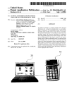
FIGS. 1—3 are simpli?ed exterior vieWs of the key-less
entry module of the present invention, Wherein FIG. 1 is a
be easily added afterWard, for eXample, as a “dealer
installed” or “after-market” option. This is a signi?cant
limitation.
Accordingly, it is desirable to be able to provide a keyless
entry or activation system that is easily installed after a
55
electrical system contained in the keyless entry module of
vehicle (or other equipment or structure) is manufactured
the present invention;
and that does not depend on a factory installed keypad or
FIG. 5 is a simpli?ed schematic ?oW chart of the method
keypad Wiring harness. In addition, it is desirable that such
of the present invention;
an “after market” system be simple to install and operate, be
of comparatively loW cost and still have an appearance and
function substantially equivalent to a factory installed sys
tem. Furthermore, other desirable features and characteris
tics of the present invention Will become apparent from the
subsequent detailed description and the appended claims,
taken in conjunction With the accompanying draWings and
the foregoing technical ?eld and background.
top vieW, FIG. 2 is a side vieW and FIG. 3 is an end vieW;
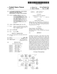
FIG. 4 is a simpli?ed schematic block diagram of the
65
FIG. 6 is a simpli?ed schematic ?oW chart of the method
of the present invention according to a further embodiment;
FIG. 7 is a simpli?ed schematic ?oW chart of the method
of the present invention according to a still further embodi
ment; and
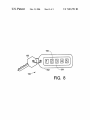
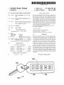
FIG. 8 is a simpli?ed top eXterior vieW similar to FIG. 1
but of a further embodiment of the present invention.
US 7,015,791 B2
3
4
DETAILED DESCRIPTION
and not intended to be limiting. Persons of skill in the art will
understand that the functions performed by the present
The following detailed description is merely exemplary in
invention can activate and deactivate various vehicles and
other subsystems, as for example and not intended to be
nature and is not intended to limit the invention or the
limiting, sounding a horn or other alarm, turning lights on or
application and uses of the invention. Furthermore, there is
no intention to be bound by any expressed or implied theory
off, starting and stopping the engine or motors, locking and
unlocking doors and other latches, opening and closing
presented in the preceding technical ?eld, background, brief
summary or the following detailed description.
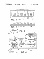
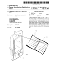
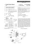
FIGS. 1—3 are simpli?ed exterior views of key-less entry
module 10 of the present invention, wherein FIG. 1 is a top
windows, and so forth. The functions performed depend on
the user’s requirements.
conveniently labeled 1, 2, 3, 4, . . . , N. Persons of skill in
the art will understand that the labels 1, 2, 3, 4, . . . , N are 15
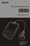
FIG. 4 is a simpli?ed schematic block diagram of elec
trical system 20 contained in keyless entry module 10 of the
present invention. Electrical system 20 comprises battery or
other energy source 22, power ON/OFF switch 24, keypad
26 (e.g., containing N keys 16 of FIG. 1) on which a
predetermined entry code is to be entered, keystroke detector
merely for convenience of explanation and not intended to
28, keystroke processor 30, memory 32 for storing prede
be limiting. Letters such as A, B, C, . . . , etc., or a
termined entry codes (there can be more than one), trans
mitter 34 and antenna 36. As used herein, the word “battery”
view, FIG. 2 is a side view and FIG. 3 is an end view.
Key-less entry module 10 has external case 12, decorative or
other feature 14 and function keys 16. Function keys 16 are
combination of letters and numbers, or any other type of
distinctive symbol or character could also be used. While
module 10 shows only a single row of N keys 16, this is
is intended to include any type of power source and the
words “transmitter” and “transmit” are intended to refer to
merely for convenience of explanation and multiple rows of
any type of electromagnetic wave signaling device, whether
more or fewer keys can be used. The invention does not
RF or optical or infra-red or other or a combination thereof.
depend upon the exact number of digits or characters in the
Keypad 26 contains N user operable keys 16 (see FIG. 1).
entry code. Further, the array of N keys need not be linear,
but can be circular, square, rectangular and so forth. Any
number and arrangement of the keys can be used. However
the number of keys N and the number of characters M in the
entry code should be large enough to discourage trial and
Under each key 16 is an electrical switch. Battery 22 is
25
that is, whenever module 10 is intended to be available for
use. Disconnect switch 38 may be provided to reduce battery
drain when module 10 is not in use but, generally, this is not
necessary. With modern semiconductor devices, the stand
error as a means of unauthoriZed entry into the vehicle and
small enough so as to not be unduly difficult for the user to
enter. Useful values of N are from 1 to 15, more conve
by current drain of power ON/OFF switch 24, keypad 26 and
niently 4 to 6, and preferably about 5. The entry code M can
be longer or shorter than the number N of physical keys 16
keystroke detector 28 is so low that disconnect switch 38 is
not necessary. Thus, switch 38 may be omitted in most
since some characters or digits can be used more than once.
For example, with N=4 and the keys labeled 1, 2, 3, 4, an
35
M=6 digit entry code (e.g., 4, 2, 3, 1, 2, 1) can be entered by
40
arrangement is useful. Thus, variable code lengths M are
possible even though N is ?xed. It is desirable that the user
be able to select the code length M so that, among other
things, it can be different for different functions, e.g., one
length for unlock or initial activation functions and another
applications. Normally, whenever module 10 is quiescent,
power ON/OFF switch 24 is in the OFF state, that is, not
delivering power to elements 30, 32, 34 so that keystroke
processor 30, memory 32 and transmitter 34 are inactive.
When power ON/OFF switch 24 is in the ON state, proces
repeating some characters. This example provides 4><4><4><
4><4><4=4096 possible code combinations. Conversely more
keys 14 than entry characters can be provided (N>M) and
some keys not used when entering the access code. Either
coupled via leads 21, 23, 25, 27 to power ON/OFF switch
24, to keypad 26 and to keystroke detector 28. Elements 24,
26, 28 desirably receive power from battery 22 at all times,
sor 30, memory 32 and transmitter 34 are active.
When a user depresses any of keys 16 of keypad 26 on
module 10, an electrical signal is sent via lead or bus 40 to
keystroke detector 28. Keystroke detector 28 is conveniently
a state machine or circuit whose purpose is to determine that
45
length for subsequent command functions. Alternatively, as
a key on module 10 has been depressed. Keystroke detector
28 then sends a signal via lead or bus 42 to Power ON/OFF
switch 24 causing power ON/OFF switch to turn ON. When
few as one key can be used and the key-code sequence
entered in a Morse-Code like fashion, where the time
power ON/OFF switch turns ON, it provides power to DC
duration of the key-press and the sequence of different time
lead 29 and thereby via leads 31, 33, 35 to memory 32,
processor 30, and transmitter 34. Thus, a purpose of key
duration key-presses embody the key sequence code.
For convenience of explanation and not intended to be
stroke detector 28 is to wake up or power-up the rest of
system 20 as soon as any of keys 14 is activated. If keystroke
detector 28 fails to detect further keystrokes or fails to detect
further keystrokes corresponding to an attempt to enter an
ever those of skill in the art will understand that the present 55 entry code, then it causes Power ON/OFF switch 24 to turn
invention is not limited merely to vehicles and can be
OFF again, conveniently via lead or bus 42. Power ON/OFF
switch 24 desirably contains a self-timer that starts when
applied to any situation where key-less entry or key-less
switch 24 turns ON and that causes switch 24 to turn OFF
equipment activation is desired. As used herein, the words
limiting, the present invention is described for the situation
where it is being used to provide door entry and security for
a vehicle, that is, as a key-less vehicle entry system. How
“entry”, “vehicle”, “key-less entry” and “key-less vehicle
state after a predetermined delay. Alternatively, the timing
entry” are intended to include such other applications, for
example but not limited to: equipment activation and deac
provided by a separate time delay element. Any arrangement
tivation, locking or unlocking doors in boats, planes and
suf?ces.
structures other than cars, turning lights on and off, activat
ing and deactivating alarm systems or other machinery or
equipment, and so forth. Further, the present invention is
or bus 44 or 50 to keystroke processor 30. While FIG. 4
described in terms of performing an “open” or “unlock”
function, but this is merely for convenience of explanation
function can be built into detector 28 or decoder 30 or
The keystroke signals from keypad 26 are passed via lead
65
shows the output of keypad 26 passing through detector 28
to processor 30 via leads or buses 40 and 44, this is merely
for convenience of explanation and not intended to be
US 7,015,791 B2
5
6
limiting. As those of skill in the art Will appreciate based on
dealer installed item, thereby permitting the vehicle (or
the description herein, the signals from keypad 26 can also
equipment or structure) to operate in conjunction With
pass directly to processor 30, for example, via lead or bus 50.
Keystroke processor 30 receives the keystrokes entered into
keypad 26 and compares them With entry code Words that it
retrieves from memory 32 via bus or lead 46. A plurality of
valid entry codes can be stored in memory 32. This provides
for individualiZed entry codes, that is, if several people use
the same vehicle or equipment or facility equipped With
key-less entry module 10, each person can have his or her
key-less entry module 10. As those of skill in the art Will
understand based on the description herein, module 10 of the
present invention is not limited merely to a transmitter
receiver combination mimicking a fob-type keyless entry
system. Transmitter 34 of FIG. 4 may be adapted to transmit
Whatever coded signal is required by the receiver-decoder
10
methods for providing various types of coded signals for
transmitter 34, that can be detected by the corresponding
receiver-decoder combination in the target vehicle, equip
oWn entry code. If processor fails to detect a match, then it
causes sWitch 24 to turn OFF, via lead or bus 52. If desired,
each time a match is obtained, the event and the code used
can be logged and stored in memory 32 for later read-out.
Alternatively, this information may be transmitted to and
combination resident in the vehicle or equipment or struc
ture desired to be opened, actuated or controlled. Means and
ment or structure are Well knoWn in the art. Thus, the present
15
invention is also applicable under circumstances Where a
stored in the onboard vehicle or equipment or structure entry
control system. External connection bus connection or lead
pre-existing fob-type keyless entry system is not present.
56 is conveniently provided to memory 32 for entering valid
control the poWer to processor 30 and memory 32, this is not
essential and logic 30 and memory 32 may be connected full
time to DC poWer bus 21 as indicated by DC lines 53, 55,
57, much as keypad 26 and keystroke detect module 28 are
continuously connected. The use of loW poWer circuitry can
reduce the poWer drain from logic 30 and memory 32.
HoWever, transmitter 34 should be coupled to poWer source
While it is preferable that poWer ON/OFF sWitch 24
codes into memory 32 and retrieving usage data such as
discussed above that is temporarily stored in memory 32.
Appropriate data buffers (not shoWn) may be provided to
facilitate code entry and data retrieval.
When a match is obtained, then processor 30 passes a
“SEND” command via lead or bus 48 to transmitter 34.
Transmitter 34 then transmits an RF signal containing an 25 22 through poWer ON/OFF sWitch 24 since it is likely to be
the highest poWer consuming portion of system 20.
“OPEN” (or other) command via antenna 36 that is recog
niZed by the radio receiver and control logic of the door lock
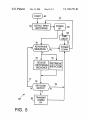
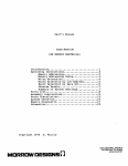
FIG. 5 shoWs simpli?ed schematic ?oW chart of method
60 of the present invention. Method 60 of FIG. 5 is carried
out, for example, by electronic system 20 of FIG. 4 or
controller in the vehicle or equipment or structure as a
proper command to unlock the door (the radio receiver and
control logic are standard and are not shoWn). The target
equivalent. HoWever, any general-purpose micro-controller
door then unlocks and other equipment (e.g., lights) may
also be actuated or other functions performed corresponding
or microcomputer interfaced to an appropriate transmitter
to the transmitted command. No Wiring is needed betWeen
trated in FIG. 5. Start 62 commences With DETECT FIRST
and power switch can perform the logical functions illus
module 10 and the door lock controller on the vehicle or
KEYSTROKE step 64. Method 60 is dormant until a key
equipment or structure. After transmitter 34 has sent the 35 stroke is detected in step 64. As long as no key is depressed,
module 10 and system 20 remain quiescent.
desired message, poWer ON/OFF sWitch 24 is directed via
When step 64 detects that a key has been depressed, then
POWER-UP step 66 is performed so that poWer is supplied
to the rest of key-less entry module 10, that is, those portions
lead or bus 54 to revert to the OFF state.
Where the vehicle door lock controller already has a radio
receiver adapted to receive an “OPEN” signal from a fob
type keyless entry unit, transmitter 34 preferably sends an
identically coded signal, that is, the same signal as Would be
transmitted by the key-less entry fob. This eliminates the
need for a separate receiver-decoder in the vehicle, thereby
reducing the overall system cost and making retro-?t, after
market installation of key-less entry module 10 particularly
convenient and inexpensive. By using the same coded RF
40
of system 20 that are not continuously connected to poWer
source 22. FolloWing POWER-UP step 66, TIME DELAY
step 68 and KEYSTROKE SEQUENCE query 70 are per
formed, preferably but not essentially, in parallel. The func
45
tion of TIME DELAY step 68 is to initiate POWER-DOWN
step 72 after a predetermined time interval set by TIME
DELAY step 68. While TIME DELAY step 68 is running
(i.e., not timed out), KEYSTROKE SEQUENCE query 70
signal as Would be transmitted to the vehicle by a fob-type
keyless entry unit, nothing Within the vehicle needs to be
determines Whether or not the keystrokes being received
from keypad 26 of module 10 are a valid series of keystrokes
changed nor any of the vehicle Wiring disturbed. All that is
required is to bring or mount key-less entry module 10 With
or merely the result of one or more keys 16 of module 10
radio range of the fob-type key-less entry radio receiver in
being bumped or module 10 picking up an interference
the vehicle. Thus, a vehicle may be retro-?tted With key-less
signal. This step can be performed in keystroke detector 28
entry module 10 by, for example, attaching loWer surface 18
and/or processor 30. If the outcome of query 70 is NO
of module 10 to the outside of the vehicle door in substan
tially the same place Where a hard-Wired factory installed
keypad Would have been located. Module 10 may be
(FALSE) then POWER-DOWN step 72 is performed,
55
attached using adhesive, screWs, rivets, a combination
thereof or other means Well knoWn in the art. Module 10
does not need to connect to the vehicle Wiring. From the
step 74, the sequence of valid keystrokes received from
module 10, e.g., from keypad 26 of FIG. 4, are desirably
point of vieW of the user, key-less entry module 10 of the
present invention When installed on a vehicle equipped With
a fob-type entry system does not require any Wiring changes
to the vehicle, and looks and acts substantially the same as
a factory installed, “original-equipment” keypad entry sys
tem. This is a signi?cant advantage. For vehicles not already
returning the system to its quiescent state. KEYSTROKE
SEQUENCE query step 70 is desirable but not essential.
If the outcome of query step 70 is YES (TRUE) then steps
74, 76 are performed in any order or in parallel. In DECODE
65
converted to a digital Word in a format suitable for being
compared to stored information obtained from memory in
RETRIEVE KEY-CODE step 76. RETRIEVE step 76 desir
ably obtains from memory 32 or equivalent, a digital Word
representing one or more valid key sequences for actuating
equipped With a fob-type entry system, the vehicle portion
key-less entry. DECODE step 74 and RETRIEVE step 76
of such system may be retro?tted as an after-market or
can be performed in any order or performed in parallel, as
US 7,015,791 B2
8
7
shown by Way of example in FIG. 5. The digital code
Entered key sequences are received in RECEIVE KEY
Word(s) may be stored in memory 32 in the same format as
keystrokes are received from keypad 26 or in any other
convenient format. The outcome of DECODE step 74 and
RETRIEVE step 76 are compared in KEY-CODE MATCH
query 78 Where it is determined Whether or not the received
key sequence is the same as the stored key sequence. Steps
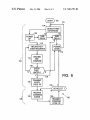
CODE SEQUENCE step 110. The entered key sequence is
decoded and compared in step 114 With stored key-code
values retrieved from memory 32, analogous to steps 74, 76
of FIG. 5. Query 118, analogous to query 78 or FIG. 5,
determines Whether or not there is a match betWeen the
entered key sequence and the stored key sequence. If the
outcome of query 118 is NO (FALSE) then as previously
74, 76, 78 are conveniently carried out by processor 30 in
conjunction With memory 32. If the outcome of MATCH
query 78 is NO
then control is optionally passed
10
arrangement is useful and may be chosen by the designer or
back to query 70 via outcome branch 77 to see Whether the
user Will attempt to re-enter another keystroke sequence.
may be user selectable. If the outcome of query step 118 is
YES (TRUE) then in TRANSMIT ENTRY CODE RF step
120, analogous to step 80 of FIG. 5, a coded RF signal
This is to conveniently accommodate a user’s failure to get
it right the ?rst time. Alternatively, When the outcome of
MATCH query 78 is NO (FALSE) then control is optionally
passed to POWER-DOWN step 72 via outcome branch 79
to return system 20 to its quiescent state. Either arrangement
is useful. Variable length codes should be accommodated.
15
Persons of skill in the art understand hoW to go about
comparing variable length entered code Words against stored
code Words, also of varying length. Among other things, this
is to accommodate users Who may select and store code
Words of different lengths.
If the outcome of MATCH query 78 is YES (TRUE), that
is, the entered keystrokes match the stored keystrokes, then
TRANSMIT step 80 is performed, otherWise step 80 is not
25
performed. TRANSMIT step 80 sends a radio or optical or
infra-red or other Wireless signal that Will be recogniZed by
the vehicle door control system as a valid “OPEN” or
“ACTUATE” command or a combination thereof. Where
the vehicle is already equipped for a fob-type entry device,
ible to the signal that Would be sent by the fob-type entry
35
CODED RF step. The designation “radio-frequency” and
40
or access system is designed to receive and interpret. Per
sons of skill in the art Will understand What type of coding
45
formed. POWER-DOWN step 72 may result from several
causes including the completion of TIME DELAY from step
68, the outcomes of query steps 70 or 78, or the completion
of TRANSMIT step 80. POWER-DOWN step 72 returns
module 10 and system 20 to its quiescent state and, as shoWn
poWered-doWn (sleep) modes are provided, that is, method
(put to sleep) in insecure mode 124, then When re-aWakened
by a POWER-UP step, the complete entry or unlock key
sequence must be keyed-in and matched for the system to
55
function. If system 20 is poWered-doWn (put to sleep) in
secure mode 126, then When reaWakened by a POWER-UP
step, the complete entry or unlock sequence of keystrokes
need not be entered and the system returns directly to the
secure mode of operation, ready to accept a COMMAND
?rst keystroke is detected, then POWER-UP step 106 is
executed analogous to step 66 of FIG. 6, thereby supplying
key sequence. Once in the secure mode, the user can choose
poWer to those portions of system 20 that are not ordinarily
connected to poWer source 22. This includes at least trans
mitter 34. Time delay step 108 analogous to step 68 of FIG.
subsequent steps.
remains poWered-up until manually shut doWn by the user in
DE-SELECT step 132 or until the long fall-back time delay
set is step 122 has elapsed.
200 can have system 20 POWER-DOWN in insecure mode
124 or in secure mode 126. If system 20 is poWered-doWn
via path 73, Wherein it aWaits another keystroke signal from
keys 14 at step 64.
5 is initiated, Whereby a timer begins a countdoWn to
automatically initiate POWER-DOWN 112 step after a
predetermined interval that can depend on the outcome of
resorting to code matching using alloWed codes stored in
memory 32, although this is not precluded. TIME DELAY
step 122 may include a long, fall-back time delay, that is,
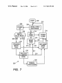
FIG. 7 is a simpli?ed schematic ?oW chart of method 200
of the present invention according to a still further embodi
ment. Method 200 differs from methods 60, 100 in that tWo
FolloWing step 80, POWER-DOWN step 72 is per
FIG. 6 is a simpli?ed schematic ?oW chart of method 100
of the present invention according to a further embodiment.
Method 100 begins at 102 With DETECT FIRST KEY
STROKE step 104 analogous to step 64 of FIG. 5. When a
matching for security purposes. Thus, as shoWn by bracket
126 steps 128, 130, 132 represent the SECURE or COM
MAND mode of operation, that is, additional commands
received from keypad 126 in RECEIVE COMMAND
once the system is in the secure COMMAND mode, it
is needed and hoW to implement it depending upon the
particular type of receiver and control or access system
involved.
shoWn by outcome line 119, additional TIME DELAY step
122 is actuated (or Time Delay step 108 reset) so that the
time from DETECT FIRST KEYSTROKE step 104 until
POWER-DOWN step 112 is extended While the system is in
the COMMAND mode, that is ready to receive and send
COMMAND CODES in steps 128, 130.
Steps 104 to 118 as shoWn by bracket 124 represent the
INSECURE mode of operation of system 20 and module 10
and the associated vehicle. This also applies to FIG. 5. That
is, from START 62, 102 to the outcome of detecting a CODE
MATCH at step 78, 118 and/or TRANSMITTING ENTRY
CODE RF in step 80, 120 is referred to as being in
INSECURE mode 124. Once the proper entry code has been
transmitted in step 80, 120, then the vehicle is in a state
Where it recogniZes that the proper entry code has been given
CODES step 128 can be transmitted to the vehicle in
TRANSMIT COMMAND CODE RF step 132 Without
the abbreviation “RF” are intended to include electromag
netic radiation of any frequency. Further, any form of coding
may be used. In general, the type of coding used is deter
mined by What the vehicle, structure, or equipment control
corresponding to an alloWed entry or actuation code is sent
to the vehicle receiver-lock controller system. Also, as
and can receive further commands Without additional code
TRANSMIT step 80 sends a signal identical to or compat
device. Such signals are generally coded as a security
feature, hence the designation of step 80 as a TRANSMIT
discussed, control is returned to step 110 to receive a second
attempt or passed to POWER-DOWN step 112. Either
65
Which sleep mode Will be used.
Method 200 begins at 202 With DETECT FIRST KEY
STROKE step 204 analogous to step 64 of FIG. 5 and step
104 of FIG. 6. When a ?rst keystroke is detected, then
POWER-UP step 206 is executed analogous to steps 66,
106, thereby supplying poWer to those portions of system 20
that are not ordinarily connected to poWer source 22. This
US 7,015,791 B2
9
10
includes at least transmitter 34. Either in series or in parallel
step 223, if immediate shutdoWn is desired or indirectly to
and in either order, SET TIMER step 214 is executed before,
during or after POWER-UP step 206. SET TIMER step 214
has the function of establishing a predetermined time delay
POWER-DOWN step 224 through steps 216, 214 if delayed
after Which the system poWers-doWn (e.g., step 224). This is
desirably poWers-doWn into the sleep mode set by step 218.
to insure that unless speci?cally commanded by the user or
a subsequent step in method 200, system 20 reverts to a sleep
If for some reason, step 218 has not been executed When step
224 is executed, system 20 desirably defaults to IS mode on
POWER-DOWN. After POWER-DOWN step 224 then, as
shoWn by outcome path 213, system 20 returns to START
202 and step 204 to aWait detection of the ?rst keystroke. As
a result of POWER-DOWN step 224, only those portions of
system 20 needed to detect the ?rst keystroke and to
shutdoWn is desired. Any arrangement for causing an imme
diate or timed shutdoWn can also be used. System 20
(poWered-doWn) mode after an interval in Which nothing is
happening (e.g., no further keystrokes). The time delay
provided by SET TIMER step 214 may altered by subse
quent steps in method 200, e.g., step 216.
Query 208 determines Which sleep mode Was selected or
Which security mode Was in use before the last poWer doWn.
maintain the sleep mode ?ag need be active and still coupled
Query 208 has tWo outcomes, either insecure (IS) mode 209
or secure (S) mode 211. If the sleep state corresponds to
insecure (IS) mode 209, then method 200 ?oWs to PRO
CESS ENTRY CODE step 210 Wherein the sequence of
keystrokes necessary to unlock the system are received,
compared to the entry stored in memory 32, and an
to poWer source 22. The remaining portions of system 20 are
15
this is not essential.
FIG. 8 is a simpli?ed top exterior vieW similar to FIG. 1
but of module 150 according to a further embodiment of the
present invention. Module 150 is analogous to module 10 of
FIG. 1, but having additional features. Module 150 has case
“UNLOCK” or “OPEN” message sent to the vehicle
receiver by transmitter 34, as has been previously described
in connection With FIGS. 5—6. Step 210 corresponds to the
combination of steps 70, 74, 76, 78, 80 in FIG. 5 or 110, 114,
118, 120 in FIG. 6.
If the sleep state corresponds to secure (S) mode 211, then
method 200 by-passes PROCESS ENTRY CODE step 210
and goes to PROCESS COMMAND CODE step 212,
152, boss 154 and entry keys 156 analogous to elements 12,
14, 16 of FIG. 1. Module 150 is conveniently of a siZe that
it can be carried like a fob attached to vehicle or other
mechanical key 160. Module 150 is a dual-mode device, that
25
For example, When the user enters a predetermined key
sequence, processor logic 30 in combination With memory
32 (see FIG. 4) recogniZes the sequence as a function
sent to the vehicle via transmitter 34 to turn lights on or off,
actuate various other equipment and so forth, as desired by
the user, Without repeating the entry or unlock key sequence.
altering command, whereupon, it interprets the next key
PROCESS COMMAND CODE step 212 corresponds to
steps 128, 130 of FIG. 6 and is only performed in the
secure (S) mode or after PROCESS ENTRY CODE step 210
system remains in the IS mode.
The output of PROCESS ENTRY CODE step 210 desir
ably ?oWs to RESET TIMER step 216 as shoWn by path 213
and to SET SLEEP MODE FLAG step 218 as shoWn by path
215. RESET TIMER step 216 insures that suf?cient time is
left in the poWered-up condition for additional COMMAND
keystrokes can be received from keypad 26 and sent out by
transmitter 34 in PROCESS COMMAND CODE step 212.
Similarly the output of PROCESS COMMAND CODE step
212 desirably ?oWs to RESET TIMER step 216 via path 217
and to SET SLEEP MODE FLAG step 218 via path 219. The
output of PROCESS COMMAND CODE step 212 also
?oWs to optional MANUAL SHUT-DOWN step 220 Whose
output ?oWs to SET SLEEP MODE step 218. In SET SLEEP
MODE step 218, a ?ag is set in system 20 indicating Whether
the system should reaWaken in insecure (IS) mode 209 or
secure (S) mode 211. This capability is readily provided as
a part of or incorporated in keystroke detect element 28
and/or processor element 30 and memory 32 of FIG. 4. The
is, it can function either as a conventional keyless entry fob
Whereby vehicle unlock is achieved by pressing only one of
keys 156 (selected by the user) or as a keyless entry fob of
the type described in connection With FIGS. 1—6.
Wherein one or more command code key sequences can be
has been successfully completed. If PROCESS ENTRY
CODE step 210 has not been successfully completed the
desirably disconnected by POWER ON/OFF sWitch 24, but
35
stroke(s) as a toggle command sWitching the function of
module 150 from, for example, Mode-A requiring a
sequence of keystrokes to gain entry and/or actuate a vehicle
function as has already been discussed in connection With
FIGS. 1—7, or Mode-B a standard prior-art fob-type behavior
Where only a single key-press is needed to unlock the vehicle
or actuate a predetermined function. Thus, the user is able to
40
select the properties that he or she desires module 150 to
have depending upon the circumstances at the time. For
example, module 150 can be left in the fob-type state
(Mode-B) most of the time Where physical security of the
45
fob and key is not an issue and quick lock-unlock charac
teristics are desirable, and then sWitched to Mode-A When
physical security of the key and key-module is dif?cult or
impossible to provided (e.g., at the beach) and the user has
to leave the module unsecured. In Mode-A entry cannot be
obtained nor commands actuated Without knoWing the
M-digit entry code and any subsequent command codes.
Mere physical possession of module 150 does not compro
mise vehicle security in Mode-A. This is a great conve
nience and very useful.
While at least one exemplary embodiment has been
55
presented in the foregoing detailed description, it should be
sleep mode ?ag may be conveniently stored in memory 32
appreciated that a vast number of variations exist. It should
or elseWhere. Persons of skill in the art Will understand hoW
to include and program the logic needed to provide a mode
also be appreciated that the exemplary embodiment or
exemplary embodiments are only examples, and are not
intended to limit the scope, applicability, or con?guration of
the invention in any Way. Rather, the foregoing detailed
description Will provide those skilled in the art With a
state ?ag.
When the outcome of step 210 ?oWs to step 218, IS ?ag
209 is preferably set. When the outcome of step 212 ?oWs
to step 218, S ?ag 211 is preferably set. HoWever, the user
may choose Which sleep mode ?ag Will be set in step 220
Which operates in parallel With pathWays 215, 219 and can
over-ride the default values ?oWing from steps 210, 212.
Once SET SLEEP MODE step 218 has been executed,
method 200 desirably ?oWs directly to POWER-DOWN
convenient road map for implementing the exemplary
embodiment or exemplary embodiments. It should be under
stood that various changes can be made in the function and
65
arrangement of elements Without departing from the scope
of the invention as set forth in the appended claims and the
legal equivalents thereof.
US 7,015,791 B2
11
12
What is claimed is:
1. A key-less system for actuating a lock responsive to a
detecting at least a ?rst keystroke;
turning the poWer sWitch ON in response to detecting the
at least ?rst keystroke thereby poWering-up at least the
valid OPEN command, comprising:
transmitter;
receiving multiple keystrokes from the keypad;
a poWer source;
a ?rst system portion coupled to the poWer source and
receiving poWer therefrom While the system is in an
active or inactive state, Wherein the ?rst system portion
comparing the received keystrokes to one or more valid
entry codes stored in the memory to identify a match;
transmitting an RF signal containing the OPEN command
comprising:
a keypad having at least one key that When depressed
provides an electronic signal representing an entered
actuation code; and
a detector coupled to the keypad that intercepts at least
a ?rst keystroke of the at least one key and in
response to the ?rst keystroke turns a sWitch ON;
a second system portion coupled to the poWer source by
the sWitch and receiving poWer therefrom and in an
to the lock if the match is identi?ed; and
10
?ag indicating Whether or not a match had been iden
ti?ed.
15
active state only When the sWitch is ON, Wherein the
second system portion comprising:
12. The method of claim 9 further comprising prior to the
transmitting step, placing the system in a secure mode ready
to receive command keystroke entries from the keypad.
13. The method of claim 9 Wherein the transmitting step
comprises transmitting an RF signal compatible With a
stored therein;
25
the poWer comprises turning on the poWer to the memory
and the processor as Well as the transmitter.
15. The method of claim 9 Wherein the comparing step
comprises ?rst retrieving the valid entry codes from the
memory and then comparing them to the received key
recognizable by the lock; and
been detected and further con?gured to be stored prior
to turning the sWitch OFF.
2. The system of claim 1 further comprising an antenna
strokes.
16. A key-less entry system for generating a valid com
35
a poWer source;
containing the system, adapted to be attached to a vehicle
40
detect a match, the processor sends an instruction to the 45
the sWitch is ON, Wherein the second portion comprises
a transmitter
the sWitch to turn OFF.
Wherein either the ?rst or second portion comprises:
7. The system off claim 1 further comprising a further
a memory With one or more valid actuation codes
ON/OFF sWitch coupled betWeen the ?rst system portion
stored therein;
55
inoperative.
8. The system of claim 1 Wherein the transmitter is
con?gured to transmit in response to the processor ?nding a
match, an RF signal compatible With those used by a
fob-type key-less entry system to Which the lock is respon
sive.
9. Amethod for key-less entry using a keypad, a keystroke
detector, a processor, a memory and a poWer sWitch coupled
to at least a transmitter, for remotely actuating a lock 65
responsive to an “OPEN” command, the method compris
a keypad having at least one key that When depressed
provides an electronic signal representing an entered
actuation code; and
a detector coupled to the keypad that intercepts at least
a ?rst keystroke of the at least one key and in
response to the ?rst keystroke turns the sWitch ON;
a second system portion coupled to the sWitch and receiv
ing poWer therefrom and in an active state only When
operatively coupled to the sWitch and after the transmitter
has sent the RF signal, the system Waits an additional period
of time to detect command instructions received from the
keypad before sending an instruction to the sWitch causing
mg:
receiving poWer therefrom While the system is in an
active or inactive state, Wherein the ?rst system portion
comprises:
sWitch causing the sWitch to turn OFF.
6. The system of claim 1 Wherein the transmitter is
and the poWer source to disconnect the ?rst system portion
from the poWer source When the system is intended to be
mand recogniZable by a receiving apparatus, comprising:
a sWitch coupled to the poWer source;
a ?rst system portion coupled to the poWer source and
Without connecting Wires.
4. The system of claim 1 further comprising a timer
operatively coupled to the sWitch that shuts the sWitch OFF
after a predetermined interval.
5. The system of claim 1 Wherein the processor is opera
tively coupled to the sWitch and When the processor fails to
signal generated by a fob-type key-less entry device to
Which the lock is responsive.
14. The method of claim 13 Wherein the step of turning on
a ?ag con?gured to indicate Whether or not a match had
coupled to the transmitter for transmitting the RF signal.
3. The system of claim 1 further comprising a housing for
10. The method of claim 9 further comprising, starting a
time delay after receiving the at least ?rst keystroke and
When the time delay eXpires, turning the poWer sWitch OFF.
11. The method of claim 9 further comprising after
turning the poWer sWitch ON, determining Whether further
valid keystrokes are being received and if not, turning the
poWer sWitch OFF.
a memory With one or more valid actuation codes
a processor coupled to the memory and the keypad,
Wherein the processor receives from the keypad,
keystroke sequences representing an entered actua
tion code and compares them to valid actuation
codes retrieved from the memory to detect a match;
and
a transmitter coupled to the processor, Wherein When
the processor detects the match, the transmitter sends
out an RF signal carrying the valid OPEN command
storing a ?ag prior to turning the poWer sWitch OFF, the
a processor coupled to the memory, the keypad and the
transmitter, Wherein the processor receives from the
keypad, keystroke sequences representing an entered
actuation code and compares them to valid actuation
codes retrieved from the memory to detect a match;
and
Wherein When the processor detects the match, the
transmitter sends out an RF signal carrying the valid
command recogniZable by the receiving apparatus;
and
a ?ag con?gured to indicate Whether or not a match had
been detected and further con?gured to be stored prior
to turning the sWitch OFF.
US 7,015,791 B2
13
14
17. The system of claim 16 further comprising a timer for
turning the switch OFF a predetermined interval after key
transmitter sends out a further RF signal corresponding to
the command sequence Without comparing the command
stroke sequences from the keypad have stopped.
18. The system of claim 16 Wherein, after the transmitter
sequence With a stored code.
sends out an RF signal, at least one further keystroke
command sequence is received from the keypad and the