1
Reference Manual
Document title
WMPro Reference Manual
Document Identity
Date
4655-002-007
2015-10-22
Valid for
Firmare version
IMSE WebMaster Pro R4.0 2.42
Webpages version
3.19
WebMaster Pro
WMPro Reference Manual
All information in this reference manual is believed to be correct and the manual is released as an aid
to all WMPro users, free of charge. Abelko cannot guarantee that there are no mistakes or faults in this
documentation, and cannot be held responsible for any consequences that result from use or misuse of
the enclosed information.
All information in this document can be changed without notice. Some information is likely to change
in future releases of the firmware. Make sure you have the latest version of this document, and that it
is valid for your version of WMPro.
Copyright Abelko Innovation. All rights reserved.
Abelko Innovation
2
WebMaster Pro
WMPro Reference Manual
.................................................................................................................................................................. 1
1.
INTRODUCTION .......................................................................................................................... 7
2.
CHANNELS .................................................................................................................................... 8
2.1. INTRODUCTION .......................................................................................................................... 8
2.2. DEFINITION ............................................................................................................................... 8
2.3. CONNECTION ........................................................................................................................... 10
2.3.1.
Update Order .................................................................................................................. 10
2.3.2.
System inputs .................................................................................................................. 11
2.3.3.
Unconnected channels .................................................................................................... 12
2.4. SCALING .................................................................................................................................. 12
2.5. MATHEMATICAL FUNCTIONS ................................................................................................... 13
3.
PARAMETERS ............................................................................................................................ 23
3.1.
3.2.
3.3.
4.
ALARMS ....................................................................................................................................... 24
4.1.
4.2.
4.3.
4.4.
5.
INDRODUCTION ....................................................................................................................... 23
DEFINITION ............................................................................................................................. 23
A WARNING ON DECIMALS ..................................................................................................... 23
INTRODUCTION ........................................................................................................................ 24
DEFINITION ............................................................................................................................. 24
ALARM CONDITIONS ................................................................................................................ 24
ALARM ACTION CHANNEL ...................................................................................................... 25
TIME CONTROL AND WEEKDAY CATALOGUE .............................................................. 26
5.1. INTRODUCTION ........................................................................................................................ 26
5.2. DEFINITION ............................................................................................................................. 26
5.3. TIME CONTROL TYPES ............................................................................................................. 26
5.3.1.
Time ................................................................................................................................ 26
5.3.2.
Calendar ......................................................................................................................... 27
5.3.3.
Week ............................................................................................................................... 27
5.4. WEEKDAY CATALOGUE .......................................................................................................... 27
5.5. SCRIPT NOTES .......................................................................................................................... 27
6.
CURVES........................................................................................................................................ 28
6.1.
6.2.
7.
DATABASES ................................................................................................................................ 29
7.1.
7.2.
7.3.
7.4.
8.
INTRODUCTION ........................................................................................................................ 28
DEFINITION ............................................................................................................................. 28
INTRODUCTION ........................................................................................................................ 29
SETTINGS / ADVANCED / DATABASES...................................................................................... 29
DEFINITION ............................................................................................................................. 30
DATABASE EMAIL DEFINITIONS .............................................................................................. 30
SUMMARY PAGES..................................................................................................................... 32
8.1. INTRODUCTION ........................................................................................................................ 32
8.2. BASIC SETTINGS ...................................................................................................................... 32
8.3. SUMMARY PAGE ROWS ............................................................................................................ 32
8.3.1.
Text, Header and Line .................................................................................................... 33
8.3.2.
Image .............................................................................................................................. 33
8.3.3.
Link ................................................................................................................................. 34
8.3.4.
Channel value, Parameter value and Alarm status ........................................................ 34
8.3.5.
Database ......................................................................................................................... 34
8.3.6.
Curve .............................................................................................................................. 35
8.3.7.
Edit parameter ................................................................................................................ 36
8.3.8.
Edit channel .................................................................................................................... 36
8.4. LIMITATIONS OF SUMMARY PAGES .......................................................................................... 37
9.
EXTERNAL DEVICES ............................................................................................................... 38
Abelko Innovation
3
WebMaster Pro
9.1.
9.2.
9.3.
9.4.
9.5.
9.6.
10.
INTRODUCTION ........................................................................................................................ 38
EXTERNAL DEVICE DEFINITION ............................................................................................... 38
DEVICE TYPE DEFINITION PARAMETERS .................................................................................. 39
CONNECTION DEFINITION ........................................................................................................ 39
DEVICE EMAIL DEFINITION ...................................................................................................... 40
WMSHARE PARAMETERS ........................................................................................................ 40
THE SCRIPT LANGUAGE .................................................................................................... 41
10.1.
10.2.
10.3.
11.
WMPro Reference Manual
INTRODUCTION .................................................................................................................... 42
LANGUAGE BASICS .............................................................................................................. 42
HOW TO READ A SYNTAX GRAPH ......................................................................................... 43
USER SCRIPTS ........................................................................................................................ 44
11.1.
ROUTINE DECLARATIONS .................................................................................................... 44
11.1.1. The Alias section ............................................................................................................. 45
11.1.2. Variables......................................................................................................................... 46
11.2.
STATEMENTS LT ................................................................................................................. 47
11.2.1. Channel and Variable assignment .................................................................................. 47
11.2.2. IF-statements .................................................................................................................. 48
11.2.3. Reset statements .............................................................................................................. 49
11.2.4. Print statements .............................................................................................................. 49
11.2.5. Call statements ............................................................................................................... 49
11.2.6. Acknowledge ................................................................................................................... 49
11.2.7. Disable and enable alarms ............................................................................................. 49
11.2.8. Set and Clear manual override ....................................................................................... 50
11.2.9. Comments ....................................................................................................................... 50
11.3.
EXPRESSIONS....................................................................................................................... 52
11.3.1. Unary operators ............................................................................................................. 52
11.3.2. Infix operators ................................................................................................................ 53
11.3.3. Parenthesis and memory requirements ........................................................................... 53
11.3.4. Reserved functions .......................................................................................................... 54
11.3.5. New expressions in R3.1 ................................................................................................. 55
11.3.6. Curves ............................................................................................................................. 55
11.3.7. Examples and error handling ......................................................................................... 55
12.
THE SCRIPT EDITOR ........................................................................................................... 56
12.1.
SYNTAX HIGHLIGHTING ....................................................................................................... 56
12.2.
INSERTING ALIASES............................................................................................................. 56
12.3.
SAVING THE SCRIPT ............................................................................................................. 57
12.4.
THE SNIPPETS INTERFACE ................................................................................................... 59
12.4.1. Editing aliases ................................................................................................................ 60
12.4.2. Saving and loading snippets ........................................................................................... 61
12.4.3. Moving and deleting snippets ......................................................................................... 61
13.
GFBI TYPE DEFINITIONS ................................................................................................... 62
13.1.
THE GENERAL FIELD BUS INTERFACE ................................................................................. 62
13.2.
THE DEVICE TYPE DEFINITION ............................................................................................ 62
13.2.1. Overview ......................................................................................................................... 62
13.2.2. Syntax ............................................................................................................................. 63
13.3.
EXAMPLE............................................................................................................................. 66
13.4.
SEMANTICS EXPLANATION .................................................................................................. 67
13.4.1. First row ......................................................................................................................... 67
13.4.2. PARAMETER, PUBLIC and PRIVATE .......................................................................... 67
13.4.3. BAUDRATE and CHECKSUM ....................................................................................... 67
13.5.
TELEGRAM DEFINITIONS ...................................................................................................... 68
13.5.1. Question compiler definition .......................................................................................... 68
13.5.2. Answer parser definition ................................................................................................. 68
13.5.3. Floating point support in R4.0 ........................................................................................ 69
13.5.4. TIMEOUT ....................................................................................................................... 69
13.6.
A MODBUS EXAMPLE ....................................................................................................... 69
Abelko Innovation
4
WebMaster Pro
WMPro Reference Manual
13.6.1. WM22-DIN power analyser from Carlo Gavazzi ........................................................... 69
13.6.2. Reading data and scaling information ............................................................................ 71
13.6.3. A general MODBUS DEVICETYPE definition ............................................................... 74
13.7.
GENERIC CRC ..................................................................................................................... 75
13.7.1. Explanation ..................................................................................................................... 75
13.7.2. Examples......................................................................................................................... 75
13.7.3. CRC16 / CITT ................................................................................................................. 75
13.7.4. CRC16 / ARC .................................................................................................................. 75
13.7.5. XMODEM / Kermit ......................................................................................................... 75
13.7.6. ZMODEM ....................................................................................................................... 75
14.
GROUP SCRIPTS .................................................................................................................... 76
14.1.
14.2.
14.3.
14.4.
14.5.
14.6.
15.
AEACOM SCRIPTS ................................................................................................................ 83
15.1.
15.2.
15.3.
15.4.
16.
INTRODUCTION .................................................................................................................... 86
WMSHARE TYPE DEFINITIONS ............................................................................................. 86
DEVICE INITIALISATION ................................................................................................... 87
17.1.
17.2.
17.3.
18.
INTRODUCTION .................................................................................................................... 83
AEACOM CONFIGURATION ................................................................................................. 83
AEACOM TYPE DEFINITIONS .............................................................................................. 84
AEACOM GROUPS ............................................................................................................... 85
WMSHARE SCRIPTS ............................................................................................................. 86
16.1.
16.2.
17.
INTRODUCTION .................................................................................................................... 76
SYNTAX ............................................................................................................................... 76
EXAMPLE............................................................................................................................. 77
SELECTION EXPLANATION ................................................................................................... 77
ITERATOR EXPLANATION ..................................................................................................... 78
GROUP STATISTICS .............................................................................................................. 81
SYNTAX ............................................................................................................................... 87
TELEGRAM UPDATE INTERVAL CODES ................................................................................. 88
EXAMPLES ........................................................................................................................... 88
APPLICATION SCRIPTS ...................................................................................................... 89
18.1.
INTRODUCTION .................................................................................................................... 89
18.2.
APPLICATION SCRIPT STRUCTURE ........................................................................................ 89
18.3.
DEFINITIONS ........................................................................................................................ 90
18.3.1. Initiators ......................................................................................................................... 91
18.3.2. Parameter definitions ..................................................................................................... 91
18.3.3. Constant definitions ........................................................................................................ 92
18.3.4. Channel definitions ......................................................................................................... 93
18.3.5. Curve definitions............................................................................................................. 96
18.3.6. Alarm definitions ............................................................................................................ 97
18.3.7. Database defines............................................................................................................. 98
18.3.8. Log entry definitions ....................................................................................................... 99
18.3.9. Flags ............................................................................................................................. 100
18.4.
PROCEDURES AND STATEMENTS ....................................................................................... 101
18.4.1. Procedures .................................................................................................................... 101
18.4.2. Assignments .................................................................................................................. 101
18.4.3. The PUTPAR statement ................................................................................................ 101
18.4.4. Call statements ............................................................................................................. 102
18.4.5. Update .......................................................................................................................... 102
19.
THE PARAMETER BANK................................................................................................... 103
19.1.
19.2.
19.3.
19.4.
19.5.
INTRODUCTION .................................................................................................................. 103
PARAMETER NUMBERS ...................................................................................................... 103
GETPAR.SSI ....................................................................................................................... 104
PUTPAR.CGI ....................................................................................................................... 104
GETPART.SSI...................................................................................................................... 105
Abelko Innovation
5
WebMaster Pro
WMPro Reference Manual
19.6.
GETPARX.SSI ..................................................................................................................... 105
19.6.1. Multiple parameter retrieval ........................................................................................ 105
19.6.2. Flag selection filter ....................................................................................................... 105
19.7.
FLAGS................................................................................................................................ 106
19.7.1. z=7 The Used flag......................................................................................................... 107
19.7.2. z=8 The Edited flag ...................................................................................................... 107
19.7.3. z=16 The Script flag ..................................................................................................... 107
19.7.4. The Show flags .............................................................................................................. 107
19.7.5. z=9 The Backup flag ..................................................................................................... 107
19.7.6. The other flags .............................................................................................................. 107
19.8.
BACKUP.PAR AND PUTPAR.PAR.......................................................................................... 108
19.8.1. The parameter bank edit interface ................................................................................ 108
19.8.2. The Appinit.ini file ........................................................................................................ 109
19.9.
NAMING RESTRICTIONS ..................................................................................................... 109
19.10.
SYSTEM PARAMETERS ....................................................................................................... 110
19.11.
COMMAND – PARAMETER NO 5.......................................................................................... 112
Abelko Innovation
6
WebMaster Pro
WMPro Reference Manual
1. Introduction
Welcome to the WMPro reference manual. This document tries to compile all the
information about the WMPro that did not fit into the user manual. Where the users
manual had the ambition to be a pedagogic and readable piece of literature, the
reference manuals main goal is make information about obscure details available in a
way where it can be found.
The reference manual has three main sections. The first, chapter 2 to 9, concerns details
about all the functionalities of the WMPro. Under Settings / Advanced are several
menus that are not fully explained in the user manual. Even for functionalities that are
explained in the user manual there still may be details that are not addressed. For all
functionalities where it is applicable a definition table with parameter numbers is
included. The parameter number is the key to access information when using OPC or
writing new web pages or specialized software that communicates over http.
The second main section, chapter 10 to 18 deals with the script language. This is the
base for all customized functionality in WMPro. How to write scripts is not explained
in the user manual, but the reference manual hold all details. The script section is
written to be more readable than the first section, but do not expect a textbook on
programming. The reference manual will explain all possibilities, but expects the user
to find out what to use it for. There are some examples, but look in the collection of
application examples on the Abelko home page for more.
Chapter 19 is the third main section and deals with the parameter bank and how to
access information in the WMPro. There are tables of parameter numbers in the first
section. The third section will teach you what to do with them.
Abelko Innovation
7
WebMaster Pro
WMPro Reference Manual
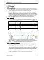
2. Channels
2.1. Introduction
The conceptual unit of a channel is fundamental to the operation of a WMPro. A
channel holds and channels the flow of information in a WMPro. It can be connected to
an input or an output, or to another channel, and in can perform mathematical
operations on the data.
The channel value is a floating point value, but the channel is also associated with a
name, a unit, mathematical parameters and options and a set of flags. Other systems in
the WMPro get information from and put information to channels. No other system
works directly on hardware inputs and outputs.
A list of all 200 channels in a WMPro is accessible under Settings / Advanced /
Channels. This list is colour coded to make it easier to identify how the channels are
used. Unused channels are white. Channels used by scripts are blue. Channels that have
been edited by a user, but are not used by a script, are yellow. A red colour indicates
that the channel is used by a script, but has not been edited. When edited and given for
example a name it will change to blue.
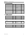
2.2. Definition
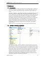
Below is a table describing the complete set of information that defines a channel, and
the corresponding parameter numbers.
Name
Type
Comment
Parameter
Name
String[32]
A name
p501
Unit
String[8]
A unit name
p502
Scale
float
Scale factor
p503
Offset
float
Offset value
p504
Connection type
byte
Type of connection
p505
Connection number
byte
Connection instance number
p506
Value
float
The channel value
p507
Decimals
byte
Number of decimals to display
p508
MathFunc
byte
Type of mathematical function
p509
MathPar 1
float
Mathematical function parameter
p510
MathPar2
float
Mathematical function parameter
p511
MathPar 3
double
Mathematical function parameter
p512
Flags
word
Flag array
p514
Name and Unit are strings of maximally 32 and 8 characters respectively. A channel
value is normally displayed as name value unit, like “Outdoor temperature 16.2 °C”.
The value of the parameter Decimals decides how many decimals to display when
printing the value. In the example this was set to 1, but may be 0 to 5.
The other parameters of a channel definition are explained in the following sections.
The Flags parameter is explained in the chapter Flags, as it is common to many systems
in WMPro.
Abelko Innovation
8
WebMaster Pro
WMPro Reference Manual
How to use the channel numbers is explained in the section about the parameter bank.
The values of a channel definition can be edited when clicking a channel in the list. The
form renames and disables MathPar 1 to 3 as appropriate from the selection of
MathFunc. In the example above they have been renamed a, b, and c.
The flags cannot be edited from the form as they are automatically handled, except for
the Backup flag. Normally a channel starts with the value zero after boot. Setting the
Backup flag to Yes means that the channel will use the last stored value instead. The
channel value is stored when the channel is edited by a user, and in a backup process
once every hour.
This flag should normally be set to No. As channels are used in normal cases the initial
value will be overwritten before it is used, and setting the flag to Yes makes no
difference.
Abelko Innovation
9
WebMaster Pro
WMPro Reference Manual
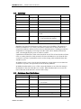
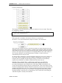
2.3. Connection
A channel can be connected to an input or an output, or it can be unconnected. The
connection type number decides the type of connection. The connection number
decides which IO of the type the channel is connected to.
Val Type
In/Out Comment and connection numbers
0
None
-
Not connected
1
DIN
IN
Digital inputs, 1to8 = DIN1 to DIN8. 9 to 16 correspond
to T1 to T8 used as digital inputs.
2
DIN_F
IN
Digital frequency inputs. 1 to 4 = DIN1 to DIN4.
3
AIN_U
IN
Analogue voltage inputs. 1 to 4 = AIN1 to AIN4.
4
AIN_I
IN
Analogue current inputs. 1 to 4 = AIN5 to AIN8.
5
AIN_R
IN
Resistance measuring inputs. 1 to 8 = T1 to T8 as
temperature inputs.
6
LED
OUT
LED outputs. 1 to 32 are LEDs on the front panel card
named LD1 to LD32. On standard hardware 1 to 8 are
DIGITAL IN, 9 to 16 DIGITAL OUT, 31 is ALARM and
32 is system.
7
DOUT
OUT
Digital outputs, 1 to 8 = DOUT 1 to DOUT8.
8
DOUT_F
OUT
Frequency outputs, none on WMPro.
9
AOUT_U
OUT
Analogue voltage outputs. 1 to 8 = AOUT1 to AOUT8.
10
AOUT_I
OUT
Analogue current outputs. None on WMPro.
11
SYS
IN
System variables. Explained separately.
12
CHANNEL
IN
Input from another channel. Connection number equals
channel number.
13
COUNTER
IN
Counter inputs. 1 to 4 corresponds to counting pulses on
DIN1 to DIN4.
When a channel is connected to an input it will each second be updated with the value
from the input, with scaling applied. If it is connected to an output the channel value
will be scaled and then put to the output.
Note on LEDs: The LEDs on a WMPro are automatically managed. Connecting a
channel to a LED will however override the automatic function. The value 0 turns the
LED of, 1 on and 2 makes it blink. LED 32 is connected to channel 200 by the
application script. The hardware is prepared for more LEDs than normally mounted,
and there are alternative positions for some LEDs.
Note on Counters: The COUNTER input type does not store counter value. When a
channel is connected it will store the counter value. Every second the channel value
will be increased by the number of counts registered in the past second.
2.3.1.
Update Order
In some cases the order in which updates occur can be important. All channel updates
starts with the lowest number channel first, i.e. from 1 and upwards. This is important
for instance when a channel has another channel as input. If the connected channel has
a higher number the value will be one second old.
Abelko Innovation
10
WebMaster Pro
WMPro Reference Manual
When scripts and alarms and other parts of the system are involved it may be important
to know the update order for all systems. The updates are synced with the IO updates,
but executed in another thread. When the signal comes that the updates are to start, the
following things are performed:
1. Input channels are updated
2. The application script is executed
3. The user scripts are executed
4. Output channels are updated
5. Alarms are updated
6. Calendars are updated
7. Databases are updated
If signal latency is important it may be good to know in which order the IOs are
updated. The analogue inputs are read one at a time throughout the interval of a second.
This is the order in which the IOs are updated, starting at the one second periodic
interrupt:
1. AIN1 and T1 are measured, Frequency measurement is updated
2. AIN2 and T2 are measured, DIN1 to DIN8 inputs are measured
3. AIN3 and T3 are measured
4. AIN4 and T4 are measured, SYSTEM UPDATE STARTS
5. AIN5 and T5 are measured, DOUT1 to DOUT8 are updated
6. AIN6 and T6 are measured, AOUT1 to AOUT8 are updated
7. AIN7 and T7 are measured
8. AIN8 and T8 are measured
There is a delay of approximately 120 ms between each point in this list. Normally the
system update will be completed before point 5, where the outputs are updated, but
there is no guarantee.
2.3.2.
System inputs
The system inputs are a kind of virtual inputs that can connect channels with system
status information. The indexes have the following meanings.
Number Value
1
Network status.
Used by the WMPro appscript to blink the system led.
2
Modem supervision output. If modem supervision is used, this signals when
the modem should be on and of. Used by WMPro appscript to connect to
DOUT8 when modem supervision is active.
3
Prognosis active. Used by ERIPX2 appscript.
4
Prognosis TOUT outdoor temperature
5
Prognosis T0. Used by ERIPX2 appscript.
6
Prognosis Te. Used by ERIPX2 appscript.
7
Prognosis Te just. Used by ERIPX2 appscript.
Abelko Innovation
11
WebMaster Pro
WMPro Reference Manual
8
Prognosis difference. Used by ERIPX2 appscript.
9
Prognosis status. Used by ERIPX2 appscript.
11
Prognosis Forecast received
11
Prognosis Forecast error count
21
Proxy online
22
Proxy error count 1
23
Proxy error count 2
31
Portal updated
32
Portal error count 1
33
Portal error count 2
101
System statistic: measure task execute ticks
102
System statistic: motor task execute ticks
103
System statistic: parbank task execute ticks
104
System statistic: parbank task period
105
System statistic: rtxc not idle ticks
106
System statistic: rtxc normalised idle count / s
107
System statistic: allocated heap size
108
System statistic: allocated heap blocks
2.3.3.
Unconnected channels
Unconnected and output channels will not be updated with new values from an input.
Values can be assigned by scripts (including graphical programmes or controllers), or
by an alarm as an action channel. If not, the value can be set manually in the user
interface. The channel value is however normally not saved, and will be reset to zero
when the WMPro boots.
It is possible to set a flag to preserve channel values. Find more information in the flags
section in chapter 19.
2.4. Scaling
When the channel is connected to an input the value from the input will be scaled using
the scale and offset parameter of the channel.
Channel Value = Scale * Input Value + Offset
Outputs are scaled according to:
Output = (Channel Value + Offset) / Scale
When there is no connection, scale and offset has no effect. When a channel is assigned
a value, in a script or from an alarm, this affects the value parameter directly with no
scaling.
Abelko Innovation
12
WebMaster Pro
WMPro Reference Manual
2.5. Mathematical functions
A mathematical function is executed after an input or an output has been updated. For
channels with no connection the mathematical function is updated at the same time as
channels with inputs.
The mathematical function makes calculations and replaces the channel value with a
new value. The three parameter called MathPar 1 to 3 are used both as input parameters
to some mathematical functions, and as state information holders for mathematical
functions with a internal states. (Note, MathFuncs for channels are not functions in the
strictly mathematical sense of the word.)
When a mathematical function stores states, these states must sometimes be cleared.
This can be done from script, but the most common usage is together with databases.
The database sets a flag that the triggers the reset. Some functions come in two
variants, one to be used with databases and one to be used with manual or periodic
resets.
States are stored before controlled reboots and once every hour. If a power failure
occurs up to one hour of information may be lost.
Below is a list of all available functions, with parameter definitions and C code
semantics.
Abelko Innovation
13
WebMaster Pro
WMPro Reference Manual
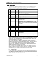
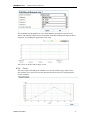
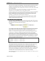
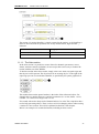
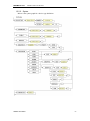
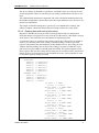
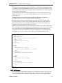
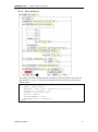
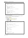
AR-filter
Auto regressive filter function. The filter factor is between 0 and 1, where 0 means no
filtering and 1 means complete disconnection.
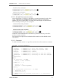
AR Filter step respons for factor 0.5, 0.7, 0.8, 0.9, 0.95, and 0.99
1
Channel value
0.8
0.6
0.4
0.2
0
0
10
20
30
Time [s]
40
MathPar1
Filter factor, a value between 0 and 1.
MathPar2
-
MathPar3
-
50
60
code
float ffact = Chn.MathPar1[i];
if (ffact > 1) ffact = 1;
Chn.MathPar1[i]) * Chn.Value[i];
Chn.Value[i] = ffact * Chn.MathPar2[i] + (1 - ffact) * Chn.Value[i];
Chn.MathPar2[i] = Chn.Value[i];
Count over
Counts every second the channel value is higher than the limit.
MathPar1
Limit
MathPar2
-
MathPar3
-
code
if (Chn.Value[i] > Chn.MathPar1[i]) Chn.MathPar3[i] = Chn.MathPar3[i] + 1;
Chn.Value[i] = Chn.MathPar3[i];
Count under
Counts every second the channel value is lower than the limit.
MathPar1
Limit
MathPar2
-
MathPar3
-
Abelko Innovation
14
WebMaster Pro
WMPro Reference Manual
code
if (Chn.Value[i] < Chn.MathPar1[i]) Chn.MathPar3[i] = Chn.MathPar3[i] + 1;
Chn.Value[i] = Chn.MathPar3[i];
Count pulse
Counts the number of times he channel value changes from under the limit to higher than the
limit. (This mathematichal function is not to be confused with the hardware supported counter
functions on DI1 to DI4.)
MathPar1
Limit
MathPar2
-
MathPar3
-
code
if ((Chn.Value[i] > Chn.MathPar1[i]) & (Chn.MathPar2[i] == 0))
{
Chn.MathPar3[i] = Chn.MathPar3[i] + 1;
Chn.MathPar2[i] = 1;
}
else if (Chn.Value[i] < Chn.MathPar1[i])
{
Chn.MathPar2[i] = 0;
}
Chn.Value[i] = Chn.MathPar3[i];
Count over DB
Same as Count over, but is reset to zero every time the value has been put into a database.
MathPar1
Limit
MathPar2
-
MathPar3
-
code
if (Chn.Value[i] > Chn.MathPar1[i]) Chn.MathPar3[i] = Chn.MathPar3[i] + 1;
Chn.Value[i] = Chn.MathPar3[i];
if ((Chn.Flags[i] & PB_CHNFLAGS_CLRDBS) > 0) CHANNEL_ResetChannelMath(i);
Count under DB
Same as Count under, but is reset to zero every time the value has been put into a database.
MathPar1
Limit
MathPar2
-
MathPar3
-
code
if (Chn.Value[i] < Chn.MathPar1[i]) Chn.MathPar3[i] = Chn.MathPar3[i] + 1;
Chn.Value[i] = Chn.MathPar3[i];
if ((Chn.Flags[i] & PB_CHNFLAGS_CLRDBS) > 0) CHANNEL_ResetChannelMath(i);
Abelko Innovation
15
WebMaster Pro
WMPro Reference Manual
Count pulse DB
Same as Count pulse, but is reset to zero every time the value has been put into a database.
MathPar1
Limit
MathPar2
-
MathPar3
-
code
if ((Chn.Value[i] > Chn.MathPar1[i]) & (Chn.MathPar2[i] == 0))
{
Chn.MathPar3[i] = Chn.MathPar3[i] + 1;
Chn.MathPar2[i] = 1;
}
else if (Chn.Value[i] < Chn.MathPar1[i])
{
Chn.MathPar2[i] = 0;
}
Chn.Value[i] = Chn.MathPar3[i];
if ((Chn.Flags[i] & PB_CHNFLAGS_CLRDBS) > 0) CHANNEL_ResetChannelMath(i);
Mean
Mean calculates the mean value over a period of time. The mean value is updated every
second, each time representing more samples. The most common use is with the Interval
parameter set to zero. The mean will then be reset when saved in database, or on script
command.
MathPar1
-
MathPar2
Interval, time in second between resets. Zero value means reset
by database.
MathPar3
-
code
if (Chn.MathPar3[i] <= 0) Chn.MathPar1[i] = 0; //reset
Chn.MathPar1[i] = Chn.MathPar1[i] + Chn.Value[i];
Chn.MathPar3[i] = Chn.MathPar3[i] + 1;
if (Chn.MathPar3[i] <= 0) Chn.MathPar3[i] = 1; //To avoid accidental divide by zero
if (Chn.MathPar2[i] > 0) {
Chn.Value[i] = Chn.MathPar1[i] / Chn.MathPar3[i];
if (Chn.MathPar3[i] >= Chn.MathPar2[i]) {
Chn.MathPar3[i] = 0;
Chn.MathPar1[i] = 0;
}
}
else {
Chn.Value[i] = Chn.MathPar1[i] / Chn.MathPar3[i];
if ((Chn.Flags[i] & PB_CHNFLAGS_CLRDBS) > 0) CHANNEL_ResetChannelMath(i);
}
Abelko Innovation
16
WebMaster Pro
WMPro Reference Manual
Variance
The variance function calculates the variance of the input signal over a period of time. The
variance value is updated every second, each time representing more samples. The variance
will be reset when saved in database, or on script command.
Variance is a measure of how much the signal has varied. The accuracy of the calculation is
limited by the resolution of floating point values and operations.
MathPar1
(mean)
MathPar2
(S)
MathPar3
(count)
code
float delta = Chn.Value[i] - Chn.MathPar1[i];
Chn.MathPar3[i] = Chn.MathPar3[i] + 1;
Chn.MathPar1[i] = Chn.MathPar1[i] + delta / Chn.MathPar3[i];
Chn.MathPar2[i] = Chn.MathPar2[i] + delta * (Chn.Value[i] - Chn.MathPar1[i]);
if (Chn.MathPar3[i] > 1)
{
Chn.Value[i] =
Chn.MathPar2[i] / (Chn.MathPar3[i] - 1);
}
else
{
Chn.Value[i] = 0;
}
Standard deviation
The standard deviation function calculates the standard deviation of the input signal over a
period of time. The standard deviation will be reset when saved in database, or on script
command.
Standard deviation is the square root of variance, a measure of how much a signal varies. One
use can be to measure how good a controller is working. A controller with the task to keep
something constant should ideally have a standard deviation of zero.
The accuracy of the calculation is limited by the resolution of floating point values and
operations.
MathPar1
(mean)
MathPar2
(S)
MathPar3
(count)
Abelko Innovation
17
WebMaster Pro
WMPro Reference Manual
code
float delta = Chn.Value[i] - Chn.MathPar1[i];
Chn.MathPar3[i] = Chn.MathPar3[i] + 1;
Chn.MathPar1[i] = Chn.MathPar1[i] + delta / Chn.MathPar3[i];
Chn.MathPar2[i] = Chn.MathPar2[i] + delta * (Chn.Value[i] - Chn.MathPar1[i]);
if (Chn.MathPar3[i] > 1)
{
Chn.Value[i] =
sqrt(Chn.MathPar2[i] / (Chn.MathPar3[i] - 1));
}
else
{
Chn.Value[i] = 0;
}
Sum
Sum adds the channel value multiplied with the factor parameter to the total sum. If the
absolute value of the total sum is higher than the limit parameter, the sum value is set to the
limit. A limit of zero means no limit.
The sum function is a time discrete integrator. It can, amongst other things, be used as
integrator in a controller, using the Limit parameter for antiwindup.
MathPar1
-
MathPar2
Factor
MathPar3
Limit, zero means unused.
code
Chn.MathPar1[i] = Chn.MathPar1[i] + Chn.MathPar2[i] * Chn.Value[i];
if ((Chn.MathPar3[i] > 0) & (abs(Chn.MathPar1[i]) > Chn.MathPar3[i])) {
if (Chn.MathPar1[i] > 0) Chn.MathPar1[i] = Chn.MathPar3[i];
else Chn.MathPar1[i] = -Chn.MathPar3[i];
}
Chn.Value[i] = Chn.MathPar1[i];
Sum DB
Same function as Sum, but is reset to zero when stored in database. Can for instance be used
to store cumulative errors in database, or on time for a digital signal.
MathPar1
-
MathPar2
Factor
MathPar3
Limit, zero means unused.
Abelko Innovation
18
WebMaster Pro
WMPro Reference Manual
code
Chn.MathPar1[i] = Chn.MathPar1[i] + Chn.MathPar2[i] * Chn.Value[i];
if ((Chn.MathPar3[i] > 0) & (abs(Chn.MathPar1[i]) > Chn.MathPar3[i])) {
if (Chn.MathPar1[i] > 0) Chn.MathPar1[i] = Chn.MathPar3[i];
else Chn.MathPar1[i] = -Chn.MathPar3[i];
}
Chn.Value[i] = Chn.MathPar1[i];
if ((Chn.Flags[i] & PB_CHNFLAGS_CLRDBS) > 0) CHANNEL_ResetChannelMath(i);
Diff
Diff, as in differentiator or difference, calculates the difference between the current value and
the last value. The difference is multiplied with the factor parameter.
MathPar1
-
MathPar2
Factor
MathPar3
-
code
Chn.MathPar3[i] = Chn.Value[i];
Chn.Value[i] = (Chn.MathPar3[i] - Chn.MathPar1[i]) * Chn.MathPar2[i];
Chn.MathPar1[i] = Chn.MathPar3[i];
Min
Min looks and holds the lowest value found in a time period. The value is updated every
second. If the interval parameter is zero, it is reset every time it is stored in a database.
Otherwise the value is reset every Interval seconds.
MathPar1
-
MathPar2
Interval
MathPar3
-
code
if (Chn.MathPar3[i] == 0) Chn.MathPar1[i] = Chn.Value[i];
//reset
if (Chn.Value[i] < Chn.MathPar1[i])
Chn.MathPar1[i] = Chn.Value[i];
Chn.MathPar3[i] = Chn.MathPar3[i] + 1;
if (Chn.MathPar2[i] > 0) {
if (Chn.MathPar3[i] >= Chn.MathPar2[i]) {
Chn.MathPar1[i] = Chn.Value[i];
Chn.MathPar3[i] = 0;
}
}
else {
if ((Chn.Flags[i] & PB_CHNFLAGS_CLRDBS) > 0) CHANNEL_ResetChannelMath(i);
}
Chn.Value[i] = Chn.MathPar1[i];
Abelko Innovation
19
WebMaster Pro
WMPro Reference Manual
Max
Max looks and holds the higest value found in a time period. The value is updated every
second. If the interval parameter is zero, it is reset every time it is stored in a database.
Otherwise the value is reset every Interval seconds.
MathPar1
-
MathPar2
Interval
MathPar3
-
code
if (Chn.MathPar3[i] == 0) Chn.MathPar1[i] = Chn.Value[i];
//reset
if (Chn.Value[i] > Chn.MathPar1[i])
Chn.MathPar1[i] = Chn.Value[i];
Chn.MathPar3[i] = Chn.MathPar3[i] + 1;
if (Chn.MathPar2[i] > 0) {
if (Chn.MathPar3[i] >= Chn.MathPar2[i]) {
Chn.MathPar1[i] = Chn.Value[i];
Chn.MathPar3[i] = 0;
}
}
else {
if ((Chn.Flags[i] & PB_CHNFLAGS_CLRDBS) > 0) CHANNEL_ResetChannelMath(i);
}
Chn.Value[i] = Chn.MathPar1[i];
RTD
The RTD mathematical function can be used to calculate a temperature from a measured
resistance for resistance dependent temperature detector. Three parameters are used to define
the sensor. R0 is the resistance at temperature T0. Alpha is a material dependent constant. The
temperature is calculated according to T = (R-R0+R0*Alpha*T0)/(R0*Alpha).
The formula is a first order approximation, an can give significant errors far from T0 for some
types of sensors. It is for example not very good for Pt1000 sensors.
MathPar1
R0
MathPar2
Alpha
MathPar3
T0
code
float R0Alpha;
R0Alpha = Chn.MathPar1[i] * Chn.MathPar2[i];
if (R0Alpha != 0)
{
Chn.Value[i] = (Chn.Value[i] - Chn.MathPar1[i]
+ R0Alpha * Chn.MathPar3[i]) / (R0Alpha);
}
Abelko Innovation
20
WebMaster Pro
WMPro Reference Manual
Thermistor
The thermistor mathematical function can be used to calculate a temperature from a measured
resistance for thermistor sensor. Three parameters are used to define the sensor. R0 is the
resistance at temperature T0. Beta is a thermistor type dependent parameter. The temperature
is calculated according to T = Beta * T0/( Beta + ln(R/R0) * T0).
MathPar1
R0
MathPar2
T0
MathPar3
Beta
code
if (Chn.MathPar1[i] != 0)
Denom = Chn.MathPar3[i] + Chn.MathPar2[i] * log(Chn.Value[i] / Chn.MathPar1[i]);
Else Denom = 0;
if (Denom != 0)
Chn.Value[i] = (Chn.MathPar3[i] * Chn.MathPar2[i]) / (Denom);
Ploynomial
The polynomial mathematical function calculates a value using a second order polynomial
defined by parameters a, b and c. The value is calculated according to a + bx + cx2, where x is
the input value. This can be used for conversions of measured values from sensors.
MathPar1
a
MathPar2
b
MathPar3
c
code
float x = Chn.Value[i];
Chn.Value[i] = Chn.MathPar1[i] + Chn.MathPar2[i]*x + Chn.MathPar3[i]*x*x;
Hourmeter
The hourmeter function counts the time, in hours, that the monitored channel is higher than a
reference value. The main use of this function is for measuring running hours on digital inputs
or outputs. Many other uses are possible.
MathPar1
Limit
MathPar2
-
MathPar3
Counter value
code
if (Chn.Value[i] > Chn.MathPar1[i])
Chn.MathPar3[i] = Chn.MathPar3[i] + 0.0002777777777777777777777777777;
Chn.Value[i] = Chn.MathPar3[i];
Abelko Innovation
21
WebMaster Pro
WMPro Reference Manual
Change_DB
The Change_DB mathematical function is always used together with a database. The channel
value is the difference between the value at the last database save and the current value. If
MathPar3 is zero the mathfunc is updated every second, else it is updated only when the
database is updated.
The intended use for this function is to monitor the daily changes of a counter or an hour
meter. Connecting a channel with Change_DB to an energy counting channel, and putting it
the day database, will enable you to record how much energy used each day.
MathPar1
Last channel value
MathPar2
Last change
MathPar3
Hold last change
code
if ((Chn.Flags[i] & PB_CHNFLAGS_CLRDBS) > 0) CHANNEL_ResetChannelMath(i);
if (Chn.MathPar3[i] == 0) //running
{
Chn.Value[i] = Chn.Value[i] - Chn.MathPar1[i];
}
else
{
Chn.Value[i] = Chn.MathPar2[i];
}
Manual Override
Manual Override adds the channel to the Manual Override menu, allowing a user to override
any value set by a script or other source. When manual override is activated the channel will
be assigned values just as normal, but when read, the manual override value (MathPar1) will
be returned instead of the true channel value.
There is a time limit for the manual override. When activated a timer starts and when it times
out manual override will be automatically disabled. When disabled automatically or by user
the true channel value will be returned again as in normal operation.
Manual override is always disabled after reset.
Activation and deactivation of manual override is done through the Show3 flag.
MathPar1
Manual Value
MathPar2
Time Limit
MathPar3
Time Counter
Abelko Innovation
22
WebMaster Pro
WMPro Reference Manual
3. Parameters
3.1. Indroduction
A parameter is in some senses similar to a channel, but unlike a channel a parameter
holds static data. The value of a parameter can only be changed by a user with operator
or config rights. It is used to parameterize a controller or other script.
A list of all 100 parameters in a WMPro is accessible under Settings / Advanced /
Parameters. This list is colour coded, just as the channels list is, to make it easier to
identify how the parameters are used. Unused parameters are white. Parameters used by
scripts are blue. Parameters that have been edited by a user, but are not used by a script,
are yellow. A red colour indicates that the parameter is used by a script, but has not
been edited. When edited and given for example a name it will change to blue.
3.2. Definition
Below is a table describing the complete set of information that defines a channel, and
the corresponding parameter numbers.
Name
Type
Comment
Parameter
Name
String[32]
A name
p900
Unit
String[8]
A unit name
p901
Value
float
The channel value
p902
Decimals
byte
Number of decimals to display
p903
Flags
word
Flag array
p905
Name and Unit are strings of maximally 32 and 8 characters respectively. A parameter
value is normally displayed as name value unit, like “Setpoint 16.2 °C”. The value of
the parameter Decimals decides how many decimals to display when printing the value.
In the example this was set to 1, but may be 0 to 5.
The values of a parameter definition can be edited in the list of parameters under
Settings / Advanced / Parameters in the web interface. The flags cannot be edited from
the form as they are automatically handled. Press save when done editing.
3.3. A Warning on Decimals
The Decimals setting only tells how many decimals will be shown, it does not round
the actual value. Setting a parameter to 3.14 and the number of decimals to 0 will give
the parameter the value 3.14, but when displayed it will be shown as 3.
This may be somewhat confusing. When the parameter is edited the next time the value
will be shown as 3. If the user then press OK this will be saved, and even though the
user believes nothing has been change, the value will actually be changed from 3.14 to
3.
A strong recommendation therefore is to always show all used decimals.
Abelko Innovation
23
WebMaster Pro
WMPro Reference Manual
4. Alarms
4.1. Introduction
Alarms are an important functionality in WMPro. Each alarm monitors one (and only
one) channel. When the set alarm criterion is met the alarm is triggered.
As alarms are well described in the user manual the reference manual will only address
some details that are not fully described in user manual.
4.2. Definition
Name
Type
Comment
Parameter
Name
String[20]
A name
p1100
Message
String[128]
Alarm message
p1101
Reset
byte
Alarm reset
p1102
TrigChnNr
byte
The number of the monitored
channel
p1103
TrigCond
byte
Alarm Condition type
p1104
TrigLimit1
float
Alarm trig limit
p1105
TrigLimit2
float
Alarm trig limit
p1106
TrigHysteresis
float
Alarm hysteresis
p1107
TrigFilterOn
Int
On filter
p1108
TrigFilterOff
Int
Off filter
p1109
TrigFilterCounter
Int
Filter counter
p1110
Action
Byte bitmask Action type
p1111
ActionChnNr
byte
Action channel number
p1112
Status
byte
Active or not
p1113
ExpectAck
byte
Waiting for ack, or not
p1114
Time
Long int
Timestamp
p1115
Flags
word
Flag array
p1116
Name
String[20]
A name
p1100
4.3. Alarm conditions
The values of TrigCond have the following meaning:
Value
Name
Condition
0
OVER
Channel > TrigLim1
1
UNDER
Channel < TrigLim1
2
BIGGER
ABS(Channel) > TrigLim1
(ABS stands for absolute value)
3
SMALLER
Abelko Innovation
ABS(Channel) < TrigLim1
24
WebMaster Pro
WMPro Reference Manual
(ABS stands for absolute value)
4
BETWEEN
(Channel > TrigLim1) AND (Channel < TrigLim2)
5
OUTSIDE
(Channel < TrigLim1) OR (Channel > TrigLim2)
6
EQUALS
Channel = TrigLim1
TrigFilterOn modifies the condition in that the condition must be true for the number of
seconds TrigFilterOn stores before the alarm is triggered. TrigFilterOff is the same
modifier for alarm deactivation. TrigFilterCounter is used internally to count for how
long time a condition has been met.
TrigHysteresis is another modifier that changes the TrigLimits for the deactivation of
an alarm. The hysteresis value is either added or subtracted from the limit, depending
on which limit and the condition type. It is used to prevent an alarm from being
activated and deactivated repeatedly when a channel value is oscillating close to a trig
limit. The trig limit is not affected by Hysteresis when the condition is EQUAL.
4.4. Alarm Action Channel
When a channel is selected as action channel for one or many alarms, the channel value
will be assigned the number of active alarms with the channel set as action channel.
The action channel update is performed in two steps. In the first step all alarms are
scanned, and all action channels are set to zero. In the second stage, after all alarms has
been updated, the alarm list is scanned again. For all active alarms with an assigned
action channel, that channel is increased by one.
Abelko Innovation
25
WebMaster Pro
WMPro Reference Manual
5. Time Control and Weekday Catalogue
5.1. Introduction
Time control is used to program the WMPro to do certain things at certain points in
time. The time control itself will evaluate to either false or true, a value that can be used
in scripts (including controllers and graphical programs).
As the time control functions are well described in the user manual the reference
manual will only address some specific information not enclosed in the user manual.
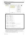
5.2. Definition
A Time Controll can be of three different types, who use the parameters in different
ways. Each time control also holds an array of time point definitions. The number of
time points is limited to ten.
Name
Type
Comment
Parameter
Name
String[20]
A name
p1700
Type
byte
0 = Time, 1 = Date, 2 = Week
p1701
Value
byte
Current state
p1702
ItemActive
Byte array
Time point used
p1717
TimeStart
Long int
array
p1704
TimeDuration
Long int
array
p1705
TimeIntervall
Long int
p1703
DateStart
Long int
array
p1706
DateStop
Long int
array
p1707
WeekStart
Long int
array
p1708
WeekStop
Long Int
array
p1709
WeekDayMask
Byte bitmask
array
p1710
Flags
word
Flag array
p1715
5.3. Time Control types
5.3.1.
Time
The Time controll type Time is used for strictly periodic time controlls. TimeIntervall
holds the length of the interval, in seconds. For each time point item there is one
TimeStart and one TimeDuration. TimeStart holds information on how long into the
period the Time Control will change state to true. TimeDuration holds for how long
time thereafter it will remain true.
Abelko Innovation
26
WebMaster Pro
WMPro Reference Manual
The periodicity is based on the real time clock. This means that if the TimeIntervall is
set to one hour, the interval will start when the real time clock passes an hour. This also
means that the Time Control might change state when the clock is set.
5.3.2.
Calendar
The calendar time control type is used for nonperiodic time control. For each time point
DateStart holds an absolute time (stored as seconds since 2000-01-01 00:00:00) when
the control will become true, and a DateStop for the time when it will stop being true.
5.3.3.
Week
The Week type is periodic for every week. Each time point consists of a WeekStart and
WeekStop, which are timpoints in a day. The WeekDayMask masks out for which
weekdays the timepoint definition is to be active. Bit 7 of the bitmask activates the
Weekday catalogue. This enables the week schedule to take public holidays and other
irregularities into consideration.
5.4. Weekday Catalogue
The weekday catalogue is stored in parameter 1712. The parameter holds up to 100
wekday replacements consisting of a date and day identifier pair, like 2004-01-01,7.
The number 7 means Sunday, and 1 would mean Monday.
The weekday catalogue can be edited as described in user manual chapter 9.3. The
default weekday catalogue is, unless something else is explicitly stated, defined for
Swedish holidays up to and including 2009.
Copying a weekday catalogue can be done by extracting information from the
backup.par file. Use the web interface to edit the weekday catalogue in one WMPro.
Retrieve the file backup.par from the device and open it in a text editor. Locate and
copy all files starting with “[RWE-]:p1712” to a new file.
To install the weekday catalogue in another WMPro upload the file to parameter bank.
This will only change the weekday catalogue in that device, without changing any other
settings.
The dates in the weekday catalogue may be entered in any order. The latest date may be
entered on the first row.
5.5. Script notes
When using script it is possible to get and use the state of a time control. That should be
no surprise. It is also possible to get information about how much time it is left until it
will change state. This widens the range of possible uses of time controls.
One possible use with the TIMELEFT function is to have the time control define when
a building is used and should be at daytime temperature. A script can use TIMELEFT
and start warming or cooling the building in advance, where the exact starting time can
be calculated from either outdoor temperature, room temperature or some combination
of information.
Abelko Innovation
27
WebMaster Pro
WMPro Reference Manual
6. Curves
6.1. Introduction
Curves are a form of interpolating look up tables (LUT). How they work and are used
is described in the users manual chapter eight. They are basically used to translate one
value (along the X axis) to another value (along the Y axis). Up to ten points can be
used to define the curve. These make up a piecewise linear function f(x).
Values higher than the largest point X-value, or lower than the lowest point X-value
will be translated to the Y value of the closest point. The value is not extrapolated from
two last or first points.
6.2. Definition
Name
Type
Comment
Parameter
Name
String[20]
A name
p1300
MaxPoint
byte
Number of defining points used
p1301
LabelX
String[20]
X-Axis label
p1302
LabelY
String[20]
Y-Axis label
p1303
ValueX
float array
Array of point X-values
p1305
ValueY
float array
Array of point Y-values
p1306
MinValueX
float
X-axis min limit
p1311
MaxValueX
float
X-axis max limit
p1312
MinValueY
float
Y-axis min limit
p1313
MaxValueY
float
Y-axis max limit
p1314
Decimals
byte
Number of decimals shown for
definition points.
p1310
Flags
word
Flag array
p1308
The point values ValueX and ValueY are addressed trough the z-values 1 to 10.
Min and Max X and Y values are inactivated if set to zero.
The decimals setting will not only affect how coordinates are displayed, but also which
coordinates can be selected graphically.
Abelko Innovation
28
WebMaster Pro
WMPro Reference Manual
7. Databases
7.1. Introduction
Databases and database emails are described in the user manual chapter 10 and how to
add things to databases is described in chapter 5. The user manual does not describe
how to use the database menu under advanced, which will be described in the next
section.
A database in WMPro is a functionality that can store selected channel values at regular
intervals in a circular non volatile buffer, and present the information stored in the
buffer in different ways. In WMPro there are three databases, and many web pages and
tools will not work unless the short time database, hour database and day database are
defined. The Goliath platform however allows up to six databases to be defined.
Each database can store up to 50 channels. The memory area however is limited. More
channels means shorter history. An internal buffer size limits the maximal history
shown to 8000 time points. The total available memory is distributed among the
databases. More databases thus mean less data in each. Each database also needs a
scrap buffer, so more databases actually means less total memory for guaranteed
database storage.
WMPro users are not recommended to play with the database definitions directly.
7.2. Settings / Advanced / Databases
The menu under Settings / Advanced / Databases lists all the channels in each of the
three databases. For the short time database it is possible to change the time base. The
default time base is one second. Storing information less often makes room for a longer
history. The interval for the Hour and Day databases are fixed and cannot be changed.
By selecting a database item from the list it is possible to change it. Any channel can be
selected, or none if the item is to be removed from the database. Every time the
database is changed, the database must be erased. The reason is that in order to save
memory only the actual values (and time point) is stored in the database. Not the
information about which value it is. If the database definition is changed it becomes
impossible to interpret the information in the database.
Abelko Innovation
29
WebMaster Pro
WMPro Reference Manual
7.3. Definition
Name
Type
Comment
Parameter
Name
String[20]
A name
p1200
Bank
byte
Memory bank used
p1201
MinSector
byte
Start sector number
p1202
MaxSector
byte
End sector number
p1203
UpdateInterval
Long int
Update interval in seconds
p1205
UpdateOffset
Long int
Interval offset in seconds
p1206
SelChnNr
Byte array
The numbers of the channels to be
stored.
p1204
PostPeriodal
byte
0 = pre periodal time stamps
p1212
1 = post periodal time stamps
Flags
word
Flag array
p1210
Databases are stored in flash memory with a sector size of 64 kByte. The memory is
banked, but databases 1 to 6 always uses bank 0. Bank 0 has 16 sectors that can be
assigned to databases. MinSector must be lower than MaxSector. Nothing prevents the
assignment of overlapping sector ranges, but the result will be databases that do not
work, even though they may seem to work for a while.
UpdateInterval defines how often values should be saved. This is based on the real time
clock, so setting interval to 3600 seconds will cause the database to save data the first
second of every hour. UpdateOffest can be used to change when within the hour data
should be saved.
In WMPro offset is set to 3599 for the hour database, causing data to be saved the last
second of every hour. The equivalent is true for the day database.
In WMPro PostPeriodal is set to 1. This causes the database to save the time stamp in
the database to the time when the save is made. When PostPeriodal is set to zero the
time of the start of the interval is saved as time stamp.
7.4. Database Email Definitions
Name
Type
Comment
Parameter
Name
String[20]
A name
p1900
Type
byte
0 = On Time
p1901
1 = On Alarm
DbsNr
byte
Database
p1902
SendInterval
Long int
Send interval
p1903
SendOffset
Long int
Send offset
p1905
SendTrigAlarmNr
Byte
The alarm that can trigger a send
p1906
SendLimit
int
Max number of rows in a mail
p1907
Abelko Innovation
30
WebMaster Pro
WMPro Reference Manual
SelSelChnNr
Byte array
Database items in the mail
p1909
Rcpt
String[47]
array
Array of four email recipients
p1910
Flags
word
Flag array
p1913
Each of the ten emails that can be defined can send a maximum of 20 channels. The
SelSelChnNr defines which channels to be included. It is not however the channel
number that is stored. It is the number of the database SelChnNr that points to the
channel. Thus changing the selection of channels that are to be stored in a database may
indirectly also affect the database emails.
Abelko Innovation
31
WebMaster Pro
WMPro Reference Manual
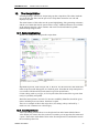
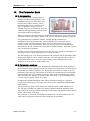
8. Summary pages
8.1. Introduction
The summary is a way to assemble and view channels, settings, curves and more that
belong in a context under one costume menu under View. The user manual has a basic
explanation of how to make summary page in chapter 14. Here you will find a list of all
the options when making a summary page.
8.2. Basic Settings
To make a new summary page go to Settings / Advanced / Summaries and select one
page. Pages that are already in use are marked with an *. Set the name of the page. This
is the name that will be shown as a new menu item on yellow background in the View
menu.
Change “Add to view menu” to Yes, and then click update. The summary page is now
available in the view menu, although it is empty.
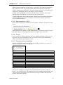
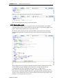
8.3. Summary page rows
For each summary page up to 20 rows may be defined. Clicking on a row brings up a
row editing window.
Each of the available options will be explained briefly.
Abelko Innovation
32
WebMaster Pro
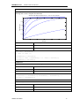
8.3.1.
WMPro Reference Manual
Text, Header and Line
Text, header and line are simple summary rows. For Text and Header a text is entered.
Line has no options. It simply invokes a line.
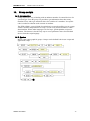
The resulting summary page looks like:
The page name is always shown at the top of the page. Under that odd rows are given a
blue background colour and even rows have white background. The text row simply
shows a row of text. The header row displays a text in bold with a blue line under it.
The line row is somewhat obsolete since the alternating background colours were
introduced. It is basically a blank row.
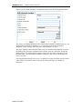
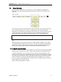
8.3.2.
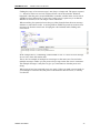
Image
The image option will show a image, provided that an image has been uploaded to the
selected user file.
Abelko Innovation
33
WebMaster Pro
8.3.3.
WMPro Reference Manual
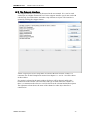
Link
A link row will put a link in the summary page. Both an URL and a help text can be
entered. The help text is optional.
Clicking on the link will open it in a new window, or a new tab, depending on the
browser.
8.3.4.
Channel value, Parameter value and Alarm status
The options Channel Value, Parameter Value and Alarm Status is quite similar in that
they show the present value of a selected object.
For each of these row the channel, parameter or alarm that is to be shown has to be
selected, and an optional help text can be entered.
On the summary page channels, parameters and alarms are shown in different colours
to make it easier to understand what is shown. The colour scheme is the same as is used
in for example graphical programming and the operator panel menu tool. Channel
names are green, parameter names blue and alarms red.
8.3.5.
Database
The database option will add a database plot to the summary page.
Abelko Innovation
34
WebMaster Pro
WMPro Reference Manual
The arguments for the database row are which database and which values are to be
shown. The amount of data can also be defined. Note that loading much data can take a
long time. Just loading the applet takes some time.
The curves are shown with a single Y-axis.
8.3.6.
Curve
The Curve option will display an editable curve on the summary page. Point can be
moved in the curve and saved, but the advanced and text based curve editing options
are not available.
Abelko Innovation
35
WebMaster Pro
8.3.7.
WMPro Reference Manual
Edit parameter
An edit parameter row makes it possible to change a parameter value from the
summary page. Edit channel value works the same way for channels.
Which parameter to edit can be selected, and an optional help text can be entered. The
type of edit must also be specified. The default method is float, allowing the user to
type any number.
The other possibility is Boolean. This will show a checkbox that is either checked or
unchecked. Unchecked corresponds to parameter value 0 and a checked box to the
value 1.
8.3.8.
Edit channel
There are four edit channel options, each deal with different channel properties.
Exactly how the edit channel math parameters row will look like depends on the math
function of the channel.
Abelko Innovation
36
WebMaster Pro
WMPro Reference Manual
Of special interest is the edit math parameters function for Hour meter math function.
This makes it possible to reset (or set any time) on an hour meter, for example after
service.
8.4. Limitations of summary pages
All text in a summary page is stored in a common memory space. This includes texts
for headers, text, help texts and URLs. The total amount of text for a summary page is
limited to 128 characters. This is not very much, and there is no warning when too
much text has been entered. The text buffer is simply truncated. After editing a page
with much text go to the view page and verify that all text looks as it was meant.
Editing text on one row may cause text on a later row to be truncated.
It is possible to leave gaps of rows of type none in the page definition. This may be a
good idea if things will be added later, as it is not possible to simply move or rearrange
the rows of a page definition.
Abelko Innovation
37
WebMaster Pro
WMPro Reference Manual
9. External Devices
9.1. Introduction
The use of external units, connections, device emails, and WMShare type definitions is
explained in the user manual. The subject will be further discussed in the script section.
This chapter will therefore mainly consist of parameter number listings.
9.2. External Device definition
Name
Type
Comment
Parameter
Name
String[20]
A name
p2000
TypID
word
Device definition ID
number
p2001
DEVICETYPEIDTEXT
String
Read only device type
name string
p2002
ComErrorTrigLimit
word
Number of failed questions p2003
to trigger the fail condition
TelegramSettings
byte array
Telegrams update settings. p2004
Code explained in script
section.
ParameterSettings
Float array
Device parameter values
DEVICETELEGRAMTEXT
String array Read only telegram name
string
p2005
p2010
DEVICEPARAMETERTEXT String array Read only parameter name p2011
string
DEVICEVALUETEXT
String array Read only value name
string
p2012
DEVICEUNITTEXT
String array Read only value unit string p2013
DEVICESTATUS
byte
Status number, 0 = ok, 1 = p2020
fail, 2 = trying
DEVICEVALUE
Float array
Device value
p2021
DEVICETIME
long int
Time of last update in
seconds since 2000-01-01
p2022
Flags
word
Flag array
p2091
External devices are more complex than the functionalities already discussed.
Information is managed not only by the parameter bank, but also by the GFBI or
AeACom motor. Only the names that are not all capital letters represents values
actually stored in the database. The other values are retrieved from the appropriate
communication motor.
The communication motors keep their own working copy of some of the information in
the parameter bank. This becomes apparent for the ParameterSettings. These settings
are copied to the motor at start-up, and whenever a new value is written. Device
parameter values can also be affected by channel connections or group scripts. This
will affect the working copy of the parameter setting, but not the value stored by the
parameter bank.
Abelko Innovation
38
WebMaster Pro
WMPro Reference Manual
9.3. Device type definition parameters
Name
Type
Comment
Parameter
DEVICETYPEIDS
word array
All defined device type ID p2030
numbers.
DEVICETYPEIDSTEXT
String array Names of all defined
device types.
p2031
These two parameters access the list of all device types defined in the scripts in the
WMPro.
9.4. Connection definition
Name
Type
Comment
Parameter
ChnNr
byte
Connected channel number p2100
DevNr
byte
Connected device number
p2101
ValNr
byte
Number of the connected
value or parameter
p2102
TypeId
word
Type ID number for the
connected device
p2103
DefaultMode
byte
0 = use at start-up, 1 = use
at start-up and error
p2104
DefaultValue
float
Default value
p2105
Time
long int
Time of last update
p2106
Status
byte
Connection / device status. p2107
0 = OK, 1 = Fail, 2 =
Trying, 3 = Disabled, 4 =
Invalid, 5 = Unused.
ActionChnNr
byte
Flags
word
p2108
Flag array
p2191
The type id number of the connected device is stored in the connection when it is
created or edited. If the external device later is changed so that the type id numbers no
longer match, the connection becomes invalid.
The connection has a non-standard use of some flags. Z=9 set to one means export, 0
import (from the device to the channel). Z = 12 is a flag for the trying state. Z = 13 set
means disabled. Z = 14 is set when the connection is invalid.
Abelko Innovation
39
WebMaster Pro
WMPro Reference Manual
9.5. Device email definition
Name
Type
Comment
Parameter
Name
String[20]
A name
p2200
TypID
word
Device type ID
p2201
EMAILDEVICETYPEIDTEXT
String
Device type name
p2202
Number of devices of
defined type
p2203
EMAILDEVICEMAXDEVICES int
SendInterval
long int
p2204
SendStartTime
long int
p2205
SendTime
long int
p2206
Rcpt
String[47]
array
Array of four email
recipients
p2208
Flags
word
Flag array
p2291
Name
Type
Comment
Parameter
Name
String[20]
A name
p2300
Key
String array Key strings
p2301
Flags
word
Flag array
p2391
Name
Type
Comment
Parameter
Server
String[47]
array
Array of four WMShare p2301
server URLs
Name
Type
Comment
SHARESELFKEY
String array Key strings
p2321
SHARESELFCHNNR
byte array
p2322
9.6. WMShare parameters
WMShare type definitions
Server urls
Export
Abelko Innovation
Channel numbers
Parameter
40
WebMaster Pro
10.
WMPro Reference Manual
The Script Language
Abelko Innovation
41
WebMaster Pro
WMPro Reference Manual
10.1. Introduction
The WMPro runs on script. It can do a few things, like measuring and
manage alarms, without scripts, but certainly not work as a controller.
Normally you do not see the scripts. You see the Controllers applet and the
graphical programming tool. In the background they generate scripts, and it
is these scripts that make the WMPro work as instructed. This and the
following chapters will reveal the secrets of the scripts and put all the
power of WMPro at your feet.
The user manual used a garden gnome as a simile to explain the script
interpreter in relation to channels, alarms and databases; A very small
garden gnome, somewhat stupid but very dedicated to its task. Every
second it wakes up and dutifully performs the tasks listed in the script files,
having access to almost all subsystems in the WMPro.
There are two script files, the Appscript.gps and the Userscript.gps. These
store the scripts in their text format. The user script is intended for the user
to edit. The user script file actually contains three different user scripts, with their own
separate program memory areas. The first is reserved for the controller applet. The
applet stores not only the script that implements the controller in this area, but also
metadata on the configuration. The second area is used for graphical programs. Both
the generated scripts and the graphical layout are stored here.
User script three however, this is where you are free to create your own scripts. It is
accessed through the script editor applet. This simple built in editor uses colour coding
to make scripts easier to read and write, and the applet hides all the other scripts stored
in the same file. When the user script is saved, it is first checked so that the syntax is
correct. If it contains errors this is reported, and the WMPro refuses to save the file.
The appscript file is part of the application, just as the web pages in appweb.bin are.
This file is distributed in update packages for WMPro. The difference between user
scripts and the appscript is that appscripts are allowed to initialize things at start-up.
The channels used for inputs and outputs are defined here, as are the databases.
Routines can be defined in the appscript, and in WMPro the system led is controlled by
a script in the appscript file. The appscript is also allowed to run special script code at
start-up. This code is allowed to do more things than the code that runs every second
can do.
If the WMPro is to be adopted for a special purpose, it may be suitable to use the
appscript to do so. When changing the appscript the WMPro will cease being a true
WMPro. It will be a new device based on the Goliath platform.
10.2. Language basics
The syntax of the script language is similar to that of Modula2 and other Pascal like
languages. It is NOT however a full featured programming language. It is designed to
be powerful and expressive enough to do everything you may need and want to do with
the platform, but in a way that prevents the programmer from making serious mistakes.
It is impossible to write a script that causes the system to crash. Of course an erroneous
script will not work, but the communication will continue and it will be possible to
replace the script file.
There are no types in the language. All operations are performed on floats. Constants in
initiations and alike can be of different types, but all variables are treated as floats and
all operators work with floats.
Abelko Innovation
42
WebMaster Pro
WMPro Reference Manual
There are no loop controls in the language. As the script itself is executed in an endless
loop they are not absolutely necessary. They are not part of the language as they
constitute an uncertainty in how long time they will need to execute, and a risk of being
or becoming endless.
There are no functions or procedures in the language, nor explicit global variables.
Subroutines exist, and channels may be used as global variables.
Scripts are stored as source code and are compiled at start-up every time. The initiation
parts of an application script are interpreted i.e. performed at the same time as the
syntax is checked. The rest of the script, that are to be executed later and possibly
repeatedly, is compiled into a binary format in a RAM-area.
The compiler has no error recovery. It will stop compiling when an error is found.
Separate user scripts are compiled separately and an error in one will not prevent
already compiled scripts from executing.
10.3. How to read a syntax graph
The syntax of the script language will be described using syntax graphs. This section is
dedicated to explain how to read and interpret these graphs. Below is an example from
the initialisation of operator panel menu structure.
To be readable, and printable, the graph is divided into sub graphs. The name submenu
in the example above is the name of this sub graph. A white box indicates a lexical
element. The keyword in the box has to be typed. The script interpreter is case
sensitive, so if a keyword is in uppercase letters it must be typed in uppercase letters.
A yellow box is a reference to another sub graph. By following a syntax graph a
syntactically correct statement, and ultimately program, can be formed. Follow the
direction of the arrows. In the example, after begin, a choice must be made. One of the
three possible lines can be followed. The bottom alternative is submenu, i.e. a reference
to itself. The lines also indicate that a loop is possible. A submenu statement may be
followed by another submenu statement.
SUBMENU “Example Headline” BEGIN
SUBMENU “Submenu 1” BEGIN END;
SUBMENU “Submenu 2” BEGIN END;
SUBMENU “Submenu 2” BEGIN END;
END;
This submenu statement is syntactically correct according to the syntax graph. Note
tough that the syntax graphs only describes how to form syntactically correct
statements. They do not explain the semantics, what the statement will do. There may
also be other restrictions on what is allowed. It is syntactically correct to define a
million levels of submenus. The compiler will object though, as there is a limit defined
in the operator panel handling routines. There are also size constraints, and memory
constraints, that can prevent syntactically correct scripts from compiling.
(Note: The operator panel menu definitions used in the example are no longer a part of
the script language.)
Abelko Innovation
43
WebMaster Pro
11.
WMPro Reference Manual
User Scripts
User scripts are scripts that are executed every second. WMPro has defined three
different user scripts with separate program memory, but they are all defined in the
same file.
The number in the script declaration states which of the three user script storage places
to be used. Between the BEGIN and END statements several routines and other
definitions can be declared. Each routine will be called every second, in the same order
as they are declared. The order between the scripts is such that the routines in the
application script are executed first, then user script one, two, and finally three.
USER SCRIPT 3 BEGIN
…
END;
If two user scripts are declared with the same number, the second will overwrite the
first.
When using the built in script editor the line “USER SCRIPT 3 BEGIN” and “END;”
will automatically be added and are not shown. You can start writing routines directly.
Routines are the basic script program element. The other possible program elements
shown in the syntax graph are related to communication and external devices.
11.1. Routine declarations
A routine is a subroutine that can be executed every second. In a user script all declared
routines will be executed once every second, in the order they are declared in the file.
A routine should take care of one specific task or subsystem in the application. This
makes the script code easier to understand and easier to reuse. If the application cannot
be broken up in smaller tasks, then one big routine might be the best solution. Routines
cannot communicate with each other than trough common channels. If two routines
have very many common channels the code may be more readable and less error prone
if they merged in to one large routine.
Below is the syntax graph for a routine:
Abelko Innovation
44
WebMaster Pro
WMPro Reference Manual
The routine_id, routine identifier, is simply a name for the routine. As al identifiers it
must be one word with no separators in it. It may include letters, digits and the “_”
character.
ASCII codes
Category
65..90, 95, 97..122, 128..255
LETTER
48-57
DIGIT
11.1.1. The Alias section
In the alias section it is possible to create aliases for channels, parameters, curves,
alarms, and time controls (calendars). In user scripts this is necessary to connect the
routine with the rest of the WMPro.
To declare an alias in the alias section, simply write a new name, an equals sign, and
then object it will represent. The object must be an existing object. To the right of the
equal sign you can use an absolute identifier, as specified by the syntax graph below:
The number between the square brackets is the index of the referenced object. For
channels this is a number between 1 and 200, parameters is 1 to 100, alarms 1 to 50,
calendar 1 to 5 and curves ranges from 1 to 10.
If it sounds awkward to keep track of channel indexes, be calm. The script editor has a
tool to help generating aliases. There is also a tool for exchanging aliases when reusing
a routine in a new context. This will be explained in detail in a later chapter.
Below is an example of a routine declaration, including an alias section.
Abelko Innovation
45
WebMaster Pro
WMPro Reference Manual
ROUTINE Example
ALIAS
Temperature = CHANNEL[1];
RefTemp
= PARAMETER[1];
PFactor
= PARAMETER[2];
TempToValve = CURVE[3];
Valve
= CHANNEL[25];
VAR
Err;
BEGIN
Err := RefTemp - Temperature;
Valve <- TempToValve(Temperature) + Err * PFactor;
END;
Note that an alias is not a C-style define. You can only create aliases for objects, like
channels and parameters. The number between the square brackets must formed by
digits. Expressions are not allowed.
11.1.2. Variables
In a routine it is possible to define local variables. This is done in the var-section,
where variable names simply are stated. Since the script language has no types, this is
all that is needed.
All variables are initialised to zero when execution starts. They are, unlike normal local
variables in Modula2, Pascal or C, persistent between calls. If a value is assigned to a
variable, the variable will hold this value until assigned another value, or until the
system is restarted.
Abelko Innovation
46
WebMaster Pro
WMPro Reference Manual
11.2. Statements LT
Statements includes assignments, if statements and other things that actually do
something. Statements_lt is the limited subset of statements that are allowed in
routines.
11.2.1. Channel and Variable assignment
The assign_var sub-graph describes the syntax for assigning variables and channels.
When a variable is assigned a value, it will store that value until it is assigned another
value. Therefore this assignment uses a unconditional assignment operator “:=”.
Assigning a value to a channel has a different syntax, as it has a slightly different
meaning. A channel is not a simple variable, it can be defined to things with the value
like filtering or summing. The operator “<-” should not be read as assign, but rather as
feed.
When a value is fed to a channel, it will hold this value until the next time it is updated.
If the channel is connected to an input the value will be overwritten with a new reading.
(Although allowed, feeding values to channel that has a source configuration, other
than an output, is considered bad programming and not recommended.) If it is
connected to an output it will act like a variable, but of course send the value, with
scaling, out to the output port.
If the channel has no source, and is not feed values from anywhere else, but is
configured to do mathematical operations, then the situation is interesting. After an
assignment, or feed, the channel will hold the value it was assigned. Before the next
call to the routine, the next second, the channel will have been updated. It then holds
the value that is the result of the mathematical operation. Using a channel this way
makes the program hard to read, and is normally not recommended.
The normal use of channel assignment is to update outputs, channels stored in
databases and channels monitored by alarms. Unconnected channels can also be used
for communication between routines, and to make internal states visible.
Abelko Innovation
47
WebMaster Pro
WMPro Reference Manual
11.2.2. IF-statements
The IF statements in the script language has a syntax like in modula2. They are very
important, as they constitute the only program flow control mechanism in the language.
If the expression after IF keyword is evaluated to a nonzero value it is considered true
and the statements after THEN will be executed. If it is zero the next ELSIF will be
tried. If no IF or ELSIF expression is nonzero the ELSE statements will be executed,
if it exists.
ROUTINE IfExamples
ALIAS
Temp
= CHANNEL[1];
Valve
= CHANNEL[25];
Force
= PARAMETER[1];
FValue
= PARAMETER[2];
Warning
= CHANNEL[50];
BEGIN
IF Temp > 95 THEN
Warning <- 1;
ELSE
Warning <- 0;
ENDIF;
IF Temp > 80 THEN
Valve <- 100;
ELSIF Temp > 60 THEN
Valve <- 60;
ELSIF Temp > 40 THEN
Valve <- 20;
ELSE
Valve <- 0;
ENDIF;
IF Force THEN
Valve <- FValue;
ENDIF;
END;
Abelko Innovation
48
WebMaster Pro
WMPro Reference Manual
11.2.3. Reset statements
The reset statement is used to reset the mathematical function of a channel that is not
reset by database updates. Se the chapter on channels for information on which
mathematical functions need reset.
11.2.4. Print statements
The print statement is a debug utility that enables trace printouts during execution. The
string and the value of the expression are printed to the debug port. It is also possible to
see them in the system log file. It should only be used temporarily for debugging.
Filling the system log file with script printouts may hide other more important system
printouts.
11.2.5. Call statements
The call statement executes the referenced subroutine. In a routine only other routines
can be called. In a procedure both other procedures and routines can be called.
In user scripts calling is less useful, as all defined routines will be executed in the order
they are defined.
In later chapters groups and iterators will be defined. Group iterators must be called
from a routine as they are not automatically executed.
11.2.6. Acknowledge
The acknowledge statement can be used to acknowledge all alarms.
The intended use is to make it possible to reset alarms by pressing a button connected
to a digital input. Use it with care!
11.2.7. Disable and enable alarms
A new feature in the 3.1 release is the possibility to disable and enable alarms from
scripts. When disabled the alarm can no longer become active. If it is active when
disabled it will become inactive if it is set to automatic. If it is set to be acknowledged it
will still be necessary to acknowledge it.
ENABLEALARM enables an alarm previously disabled with DISABLEALARM.
The intended use for these commands is to make it easier to disable alarms that are not
valid in certain operational modes, such as when a machine is not running, or to disable
alarms for optional features that are not enabled.
Abelko Innovation
49
WebMaster Pro
WMPro Reference Manual
11.2.8. Set and Clear manual override
A new feature in the 3.1 release is a possibility to set and clear manual override from
scripts. CLRMANUALOVERRIDE disables manual override for the argument
channel. This can be useful if there are certain states when stupid users should not be
able to manually override your clever program.
SETMANUALOVERRIDE makes the interface symmetrical, and maybe it will be
useful to someone sometime.
The statements are equal to check and uncheck the manual override checkbox in the
web interface.
11.2.9. Comments
To make comments, use the “%” sign. The rest of the line will be treated as a comment.
ROUTINE StatementsExample
ALIAS
LeftEnd
= CHANNEL[17]; %Left end reached (DIN)
RightEnd
= CHANNEL[18]; %Rigth end reached (DIN)
GoLeft
= CHANNEL[25]; %(DOUT)
GoRigth
= CHANNEL[26]; %(DOUT)
TimeLeft
= CHANNEL[50]; %Counting on time for GoLeft
TimeRigth = CHANNEL[51]; %Counting on time for GoRigth
VAR
Direction;
BEGIN
IF Direction = 0 THEN
GoLeft <- NOT LeftEnd;
GoRigth <- 0;
ELSE
GoLeft <- 0;
GoRigth <- NOT RightEnd;
ENDIF;
IF LeftEnd AND (Direction = 0) THEN
Direction := 0;
RESET(TimeLeft);
PRINT("Left end reached, Direction = ", Direction);
ENDIF;
Abelko Innovation
50
WebMaster Pro
WMPro Reference Manual
IF RightEnd AND (Direction = 1) THEN
Direction := 1;
RESET(TimeLeft);
PRINT("Right end reached, Direction = ", Direction);
ENDIF;
CALL IfExamples;
END;
This is an example on print, reset and call statements, as well as on comments. The idea
behind the example is some sort of system going back and forth between two
endpoints. Every time and endpoint is reached the direction is changed, and a debug
message printed.
TimeLeft and TimeRight are supposed to be channels that count the on time for the
GoLeft and GoRigth outputs. The counters are reset every time the direction is
changed. They could be monitored by alarms to detect fault conditions, when the
endpoint is not reached in reasonable time.
Abelko Innovation
51
WebMaster Pro
WMPro Reference Manual
11.3. Expressions
Expressions are mathematical expressions that will result in a single number. An
expression may be a single digit, or a complex mathematical formula with references to
channels, variables, parameters and curves.
This syntax graph is somewhat complex, yet expressions are quite intuitive. Starting in
the middle section, with the simple number. There is not much point in showing a
syntax graph for numbers. They consist of the digits 0 to 9, and optionally a decimal
point followed by more digits.
Channels can be referred either by an alias or define name, or the CHANNEL keyword
with the index in angle brackets (as shown in alias examples). The same is true for
parameters, except that the keyword is PARAMETER. Variables and constants are
referred to by name.
“res_const” stands for reserved constant and are names that represents a constant value
defined in the language itself. This category has only one member: PI.
11.3.1. Unary operators
An unary operator is an operator that operates on a single operand. The operand is to
the right of the operator. The minus sign will negate the value standing on the right side
of it. This means that writing –1.23 becomes syntactically correct.
Abelko Innovation
52
WebMaster Pro
WMPro Reference Manual
The NOT operator is a Boolean operator. All Boolean operators treat a nonzero value as
true, and zero as false. The not operator will make nonzero values zero, and change
zero values to the nonzero value of one. All Boolean operations in the script language
resulting in the value true will be represented by the value one.
11.3.2. Infix operators
Infix operators work on two operands, and is placed between the two operands. In an
expression with infix operators precedence is important. 4 / 2 + 2 is 4 and not 1,
because the / operator has higher precedence than +.
The table below lists all infix operators with highest precedence first.
Operator
Boolean result Comment
XOR
X
OR
X
AND
X
Exclusive or
^
Power, x^y is the same as xy.
*
Multiplication
/
Division
MOD
Modulus, 11 MOD 5 is 1.
-
Subtraction
+
Addition
<>
X
Not equal
<=
X
Smaller than or equal
>=
X
Bigger than or equal
<
X
Smaller than
>
X
Bigger than
=
X
Equals
Operators with a Boolean result will return either one or zero. Note that the NOT
operator has higher precedence than XOR.
11.3.3. Parenthesis and memory requirements
The syntax allows the use of parenthesis in expressions. 4 / (2 + 2) is 1. Use parenthesis
when it is required, when it makes the expression easier to understand and when there
are doubts on how the precedence works.
There is no optimisation during compilation of a script. Expressions will be stored and
evaluated as they are written. When they are stored in binary form it is the meaning of
each operator and operand that is stored, not the text itself. A plus operator takes only
one byte in the source code file, but 14 in compiled binary form. A pair of parenthesis
also takes 14 bytes to store. A constant value always takes six bytes in compiled form.
It will not matter if it is written as 1 or 1.00000000000000.
The lesson from this is that it is good practise to write expressions in a precise manner.
Writing x * 14 / 4 instead of x * 3.5 will make the script interpreter execute the 14 / 4
division every time.
Abelko Innovation
53
WebMaster Pro
WMPro Reference Manual
11.3.4. Reserved functions
It was stated earlier that there are no functions in the script language. It is true that you
cannot define your own functions, but there are built in functions.
This is standard library functions and should not require many comments. Angels are
presented in radians. The SIGN function returns –1 for negative arguments, 1 for
positive and 0 if the argument is zero. The TIMELEFT function returns the number of
seconds left to the next predicted state change of a time control.
There are also a few functions that do not take an argument.
Abelko Innovation
54
WebMaster Pro
WMPro Reference Manual
TIME returns the number of seconds since 1/1 year 2000. This function is depricated
and should not be used. The problem with it is that a float cannot store that large
numbers without losing significance. The value changes only every 16:th second (year
2006) and as the number grows it will change even more seldom.
With the release of WMPro 2.0 six new time functions are available. They return
different parts of date and time, as presented by the real time clock.
RAND and RANDN return random numbers. RAND returns a uniformly distributed
random number between 0 and 1. RANDN returns numbers with the approximate
N(0,1) normal distribution.
11.3.5. New expressions in R3.1
In R3.1 a new expression is available to check whether a channel is in manual override
or not.
If the channel has the manual override math function set, and manual override is active
(the Show3 flag is set), the expression returns one. Otherwise it returns zero.
11.3.6. Curves
Curves can also be called as functions. The curve identifier should be followed by an
argument expression in parenthesis. The curve function looks up the interpolated y
value corresponding to the argument x value.
11.3.7. Examples and error handling
Below is a table with example expressions and what they evaluate to. X, y and z are
variables assigned the values 4, 2, and 100.
x := 4.000000
y := 2.000000
z := 100.000000
x^y+0.5*z
SIN(PI/2.0)
FLOOR(11/5)
11 MOD 5
x=2
x=2*y
x AND y > z
SIGN(x * -PI)
SQRT(x)
SQRT(-1)
2/0
LN(-1)
LOG10(0)
66.000000
1.000000
2.000000
1.000000
0.000000
1.000000
0.000000
-1.000000
2.000000
0.000000
999999939489602418518643389688.804746
-999999939489602418518643389688.804746
-999999939489602418518643389688.804746
The last four examples are examples of illegal mathematical operations. They do
however give results anyway. The results are the most reasonable results possible, and
will prevent the system from crash. The last three are large numbers that represents
positive and negative infinites.
Abelko Innovation
55
WebMaster Pro
12.
WMPro Reference Manual
The Script Editor
Selecting Settings / Advanced / Script brings up the script editor. The editor loads the
user script file, but filters out the part of user script three meant for user edit and
displays only that.
The main features of this editor are the syntax highlighting, alias generating assistance,
and the save button that checks syntax before saving. Additional features are available
in the snippets interface, where routines and can be saved and loaded in goliath
platform skript snippets files.
12.1. Syntax highlighting
Below is an example of a script in the script editor.
Important keywords, such as begin, end, if, then etc, are shown in blue, and made bold.
Other script keywords that appear are coloured green. Note that the script interpreter is
case sensitive and that all keywords must be typed in capital letters.
Colour coding work as you type, so if a keyword does not become blue or green when
ready it is probably misspelled.
Identifiers and operators are black. To increase readability Identifiers should be given
names including lowercase letters. Numbers are pink.
There is no example of this in the script above, but strings, always enclosed by “”
marks are red. Comments are coloured grey.
12.2. Inserting Aliases
Above the editing window there are to drop down lists and a button labelled Insert
Alias. When you come to the alias section of a routine you can type the alias name and
a space. Then select which kind of alias in the first drop down list, and then the item in
the second drop down list.
Abelko Innovation
56
WebMaster Pro
WMPro Reference Manual
When you click Insert Alias the alias line will be finished for you.
The comment includes the name of the aliased object.
12.3. Saving the script
To save a script simply press save. The file will be sent to the WMPro. The WMPro
will check if the syntax is correct, and if it is the file will be saved and the WMPro will
reboot. When it starts again the new script will be active.
If, however, there is an error in the script, the WMPro will return an error message
instead of saving the file. The error message is shown in the message window in the
bottom.
In the example above an x has been inserted right after BEGIN, making that keyword
invalid. When saving the WMPro replies after a few seconds with the message
“UserScript.gps line 568 col 8 Syntax error: Expected ';', Found 'Timer'”.
First, don’t be confused by the high line number. The line number refers to the whole
userscript file, which may include controllers, graphical programs and other things you
do not se. The position of the cursor is always shown above the message window. The
erroneous x was inserted at row 567 col 7.
Abelko Innovation
57
WebMaster Pro
WMPro Reference Manual
Finding the cause of an error message is not always a simple task. The parser expected
a ‘;’ instead of Timer on row 568, but that will not correct the misstake. What has
happened is that the parser accepted BEGINx as another variable name, and as such it
should have been followed by a semi colon. In this case it is quite easy to se that the
BEGINx is incorrect, as it is no longer colour coded blue.
When searching for syntactical errors they are either located where the error message
indicates or somewhere earlier. A missing END or ENDIF keyword can result in error
messages far from the actual error. Keeping the code indented makes finding such
errors easier.
In the example above, commenting out the ENDIF on row 571 cases an error message
for row 585, where the routine ends.
This is also an example of multiple error messages on the same error. Do not let the
multiple messages confuse you, the parser always stops on the first error it encounters.
The multiple messages is only there to give you extra hints on what the parser was
doing.
When an error has been corrected press save again. Unless you made a new mistake in
your attempt to correct the first, the parser will continue to the next error, or actually
save the file.
Abelko Innovation
58
WebMaster Pro
WMPro Reference Manual
12.4. The Snippets Interface
The snippets interface is just briefly discussed in the user manual. It is a tool to work
with scripts on a higher abstraction level. In the snippets interface you do not work with
code directly, but with routines and other script elements as objects. The interface is
opened by clicking the snippets button.
All the script objects in user script three are listed in the main window. If there is a
comment, like for the ExampleCtrl routine from chapter 11.1 and 11.3 it will be shown
in this window.
If a routine is selected in the main window all aliases will be shown in table at the
bottom half of the window. The alias name and type is listed in the first columns. If
there is a comment on the alias row it will be shown in the column labelled Description.
The rightmost column shows the name of the channel or other object the alias is
connected to.
Abelko Innovation
59
WebMaster Pro
WMPro Reference Manual
12.4.1. Editing aliases
This table is not only a pretty tool to look at routines with; you can actually change the
alias connections here. By clicking on an element in the connection row you get a drop
down list showing all objects of the specified type in the WMPro. You can select a new
object for the alias.
Pressing Apply will transfer all changes you have made in the snippets tool to the editor
window, and close the snippets interface. If you press close all changes will be ignored.
The changes will not be saved to the WMPro unless you also press save in the script
editor window.
Abelko Innovation
60
WebMaster Pro
WMPro Reference Manual
It is only routines that have an alias section that will show anything in the alias table.
12.4.2. Saving and loading snippets
The main reason for the snippets interface is to make it easy to reuse routines and to
load device type definitions and other code to get external devices work.
The save to file button saves the selected snippet to a .gpss file. Gpss stands for goliath
platform script snippet. Insert from file load snippets from a file. A .gpss file can
contain several snippets, and they will be inserted after the selected snippet, or first if
no snippet is selected.
Remember to press apply and then save to activate the loaded script snippets.
Snippets for external devices will normally not need any editing, but if a routine with
an alias section is loaded it may be a good idea to check out that the aliases are
connected to appropriate objects in the WMPro you are working with. When writing a
routine that will be reused, make sure you use alias names and comments that helps the
user to make correct connections.
12.4.3. Moving and deleting snippets
By using the up and down buttons in the snippets interface you can change the order of
the snippets in the file. For routines the order in the file determines the execution order,
which may be crucial. For snippets that has references to other snippets the order is also
important. A reference to something that has not yet been defined renders a syntax
error.
Abelko Innovation
61
WebMaster Pro
13.
WMPro Reference Manual
GFBI Type Definitions
13.1. The General Field Bus Interface
The DEVICETYPE definition defines a class of external devices on RS485 using the
General Field Bus Interface (GFBI). GFBI is general, but with limits. It can handle
protocols on the RS485 that follows these criteria:
The WMPRo is master, slaves are quiet unless they answer a question from
the master.
The size of a correct answer to a specific question is constant and known.
Data is in binary form, no strings.
The checksum or crc method can be handled by GFBI. (Should be true for
most protocolls.)
The units accepts an intertelegram gap of 3.5 characters (silence) as legal.
The communication speed is between 300 and 115200 bps.
Different device types using different protocols can be connected at the same time,
provided that they do not interfere with each other. Care must also be taken in each
system so that the computational power of the WMPro is sufficient to handle all
connected devices as expected.
The GFBI handles telegrams. The device type definitions define how a question
telegram should be compiled. The GFBI motor sends this telegram on the RS485 line
and starts to listen for an answer of the correct size. If one is received within the
timeout period it is parsed using the reply definition.
Telegram settings accessible from the external device settings page decide the
minimum delay between how often a specific question is asked. Only one question can
be sent to a specific device every second, but GFBI can send question to many devices
during the same second.
13.2. The Device Type Definition
13.2.1. Overview
Each device type has a name, visible in web pages, and a type number. The type
number is what truly identifies the definition, and must be unique. The script name also
used is less important.
As mentioned before the definition holds a number of variables, some with public
names as parameters, other with public names as values and some are only for script
use.
The communication speed and checksum type is defined for all telegrams, and then the
telegrams themselves are defined. Telegram definitions consist of a question compiler
and an answer interpreter. The web page interface limits the number of telegrams to
ten, each with a public name
Abelko Innovation
62
WebMaster Pro
WMPro Reference Manual
13.2.2. Syntax
Below is the syntax graph for a device type definition.
Abelko Innovation
63
WebMaster Pro
WMPro Reference Manual
Where namedef has the following syntax graph:
The first string is the actual name. The optional string within brackets defines a unit and the
optional last keyword defines the formating when the value is printed.
Abelko Innovation
64
WebMaster Pro
WMPro Reference Manual
The syntax graph for a framecompiler and a frame interpreter follows:
Abelko Innovation
65
WebMaster Pro
WMPro Reference Manual
13.3. Example
Below is an example for a definition of a device using a propriety protocol (a
KomfortEl41F from Abelko, an apartment heat control unit).
DEVICETYPE KomfortEl41F NAMED "KomfortEl41F" TYPEID 1003
IS
PARAMETER
Id :"Address";
sbTemp :"Set back temperature" ["°C"];
PUBLIC
inTemp :"Apartment Temp" ["°C"];
Z1 :"Zon1" ["°C"];
Z2 :"Zon2" ["°C"];
Z3 :"Zon3" ["°C"];
Z4 :"Zon4" ["°C"];
DI :"Digital Input";
Boiler :"HotWater";
PRIVATE
Outdoor;
BAUDRATE 9600;
CHECKSUM SUM8;
TELEGRAM ReadStat NAMED "R Stat" IS
QUESTION
DATA[0] := HEX(01);
DATA[1] := HEX(FE);
DATA[2] := HEX(06);
DATA[3] := HEX(52);
DATA[4] := HEX(AD);
DATA[5] := BYTE(Id);
DATA[6] := HEX(00);
DATA[7] := HEX(FF);
DATA[8] := HEX(FF);
ANSWER SIZE 24
DATA[0] = HEX(01);
DATA[1] = HEX(FE);
DATA[2] = HEX(14);
DATA[3] = HEX(52);
DATA[4] = HEX(AD);
DATA[5] = BYTE(Id);
DATA[6] = HEX(10);
DATA[7] -> WORD(Z1 := 0.1*ROUND((DATA / 25.6)););
DATA[9] -> WORD(Z2 := 0.1*ROUND((DATA / 25.6)););
DATA[11] -> WORD(Z3 := 0.1*ROUND((DATA / 25.6)););
DATA[13] -> WORD(Z4 := 0.1*ROUND((DATA / 25.6)););
DATA[15] -> WORD(inTemp := 0.1*ROUND((DATA /
25.6)););
DATA[19] -> BYTE(DI := DATA;);
TIMEOUT 1000
END;
END;
Abelko Innovation
66
WebMaster Pro
WMPro Reference Manual
13.4. Semantics explanation
13.4.1. First row
The first row, from DEVICETYPE to IS, is not very complicated. The identifier
directly after the DEVICETYPE keyword is there for consistency more than anything
else. It is not possible to reference a device type by this name from anywhere else in a
script. The TYPEID number is the only way to reference a type. The reason for this is
that the name follows normal scope rules, and does not survive between different
scripts. It should however be possible to access a device type defined in application
script from a user script, and using the device number it is.
The device number is a number between 1 and 65535. Each device type must have a
number that is unique in the WMPro. To avoid potential errors and confusion they
should be truly unique.
The NAMED string is the name for the device type as it will be presented on the web
pages.
13.4.2. PARAMETER, PUBLIC and PRIVATE
After the PARAMETER keyword all parameter variables are defined. The definition
consists of an identifier and a name string. The name string is used on the external
device settings page, as parameter values can be set by the user. After the name string
comes, optionally, a unit string and a format specifier. In the script these variables are
not assignable.
The variables after the keyword PUBLIC are pretty much the same, but these are true
variables, and their string names and values are presented on the external devices view
page.
Variables defined after PRIVATE does not have an associated string, as they are not
presented to the user.
13.4.3. BAUDRATE and CHECKSUM
The BAUDRATE definition sets the baudrate for all telegrams. The number must be
between 300 and 115200.
The CHECKSUM definition defines what kind of checksum is used on the telegrams. It
is used both on questions and replies.
SUM8 is simply the sum of all bytes, stored in a single byte. ZSUM8 is the same thing,
but the checksum value is such that the sum of all bytes including the checksum is zero.
The optional SKIP number defines that a number of bytes in the beginning should not
be part of the checksum.
SUM16 and ZSUM16 is basically the same thing, but with word (16 bit) size sums. For
these there is also the option SWAPPED. In the WMPro integers are stored in the big
endian style, with the high byte last. If the protocol uses little endian, use SWAPPED.
The MODBUS keywords sets the checksum to be modbus style CRC. The swapped
and skip keywords can be used here to. The CRC8 and CRC16 keywords starts a
general CRC definition. This is explained in detail in section 12.7.
If the checksum is not placed last in the telegram, use the POSTBYTES keyword to
define how many bytes comes after the checksum.
Abelko Innovation
67
WebMaster Pro
WMPro Reference Manual
13.5. Telegram definitions
A device type definition can have up to ten telegram definitions. Each telegram defines
a string that is used in the settings page for external devices, where the user can set how
often, if at all, a question should be asked.
13.5.1. Question compiler definition
The question part of a telegram definition states how the frame sent to the external
device should look like. Each byte of the frame must be defined. This is done assigning
values to a data array. DATA[n] represents the n’th byte in the frame. It can be
assigned to a value using colon equals “:=” assignment.
The simplest form of assignment is using HEX, where the byte is assigned a constant
hex value. The HEX function only accepts a single byte value, described by two letters.
A to F must be capital when used.
The BYTE, WORD and RWORD takes an expression as argument. The only identifiers
in scope are the variables and parameters defined in the DEVICETYPE, but
calculations can be made on them.
With the BYTE keyword the value is typecasted to a char and assigned to the byte.
WORD and RWORD typecasts the value to and int, and assigns it to byte n and n+1.
Word uses big endian and RWORD little endian.
FLOAT stores the value as a four byte float.
When using the left arrow assignment “<-” one or several statements are expected
between the left and right parenthesis after the keyword. Allowed keywords are BYTE,
WORD, RWORD, and FLOAT. The execution of the statements must result in that the
special variable DATA is assigned a value. DATA is an automatic variable that is in
scope for these statements. The main intended use for this construct is to allow IFstatements.
The GFBI automatically appends the checksum as defined after the highest frame index
used. If not all bytes in the frame are assigned a value the result is unpredictable.
13.5.2. Answer parser definition
For an answer the expected size, in bytes, must be defined. Any reply with the wrong
size is considered faulty.
The checksum must also be correct. A special counter keeps track of checksum errors.
It is accessible from the view external devices page, along with other communication
statistics for each device.
Next step in validating the answer is by the answer parser. Individual bytes and words
in the received frame are accessible with the DATA[n] keyword, as for the question
compiler. Here data is not assigned, but with equal operator a check is made that the
data in the frame equals the expression on the right side of the equal sign. HEX, BYTE,
WORD, RWORD and FLOAT are used exactly as they are in colon equals assignment
in questions.
If one or more equalities do not hold the frame is considered faulty. A format error
counter will be increased. The parsing will stop when the first mismatch is found.
Abelko Innovation
68
WebMaster Pro
WMPro Reference Manual
Hopefully some answer will also contain some useful information. To use information
the use, right arrow, assignment is used. This compares with the left arrow assignment
in the question compiler definition. BYTE, WORD, RWORD, and FLOAT keywords
are allowed, and statements are expected between the left and right parenthesis. The
difference is that the automatic variable DATA will have been assigned with the value
from the frame. The normal use of this construct is to assign a scaled version of DATA
to a public or private variable.
13.5.3. Floating point support in R4.0
In Release 4.0, with firmware 2.4.2, FLOAT support has been extended. New
keywords interpret and generate IEEE floating point values with different byte order.
FLOAT, byte order ABCD, native byte order
RFLOAT, byte order DCBA, Reversed byte order
BSFLOAT, byte order BADC, Byte swapped order
WSFLOAT, byte order CDAB,Word swapped order
13.5.4. TIMEOUT
The last part of a telegram definition is the timeout. This is the number of milliseconds
the GFBI will wait for a reply before giving up.
13.6. A MODBUS Example
MODBUS is a standardized protocol on RS485. Information on MODBUS is available
at www.modbus.com. The standard specifies how a frame should look like, with a
header and a CRC. It also specifies some standardized function numbers and how they
should work, and exception codes.
Data is accessed trough registers. Register addresses and their contents is device and
manufacturer specific. There should be a specification available for each MODBUS
device specifying which function codes are supported and what register addresses are
used, and how to interpret their value.
Writing a GFBI devicetype specification for a MODBUS device should be quite
straightforward. MODBUS on RS485 comes in two flavors, RTU and ASCII. RTU is
the binary form, and the one that can be handled with GFBI. The MODBUS standard
says that all slaves must support RTU mode. ASCII mode is optional.
Address
Function
Code
DATA
CRC
CRC
Basic outline of a MODBUS frame.
13.6.1. WM22-DIN power analyser from Carlo Gavazzi
In this example we will write a type definition for a power analyser from Carlo
Gavazzi, the WM22-DIN. The protocol specification document states that that this
module uses MODBUS-RTU on RS485 with 9600 baud, one start bit, 8 data bits, one
stop bit and no parity. This mean that it should work just fine with the GFBI.
This unit does many things, but we want to read voltage, current and power on three
phases. We will however begin with something simple. In the specification document
there is a description on how to read an instrument type identification code. This code
should be 14. The question to send is:
01h 04h 00h 0Bh 00h 01h 40h 08h
Abelko Innovation
69
WebMaster Pro
WMPro Reference Manual
The instrument should reply with:
01h 04h 02h 00h 0Eh 38h F4h
The first byte is the slave address; the second is the function code. Four is the code for
read register. In the question the next two bytes is the register address, followed by two
butes specifying the number of registers we want to read. The last two bytes is the
CRC.
The reply starts with the same two bytes as the question. The third bytes is the number
of bytes that follows before the CRC. Then come two bytes of data, the instrument type
code. Last is, as always, two bytes of CRC.
Below is code for a DEVICETYPE for WM22, with a telegram definition to read the
instrument type code.
DEVICETYPE WM22 NAMED "WM22-DIN" TYPEID 2001 IS
PARAMETER
Id :"Address";
PUBLIC
TypeCode :"Type Code";
L1U :"L1 Voltage" ["V"];
L2U :"L2 Voltage" ["V"];
L3U :"L3 Voltage" ["V"];
L1I :"L1 Current" ["A"];
L2I :"L2 Current" ["A"];
L3I :"L3 Current" ["A"];
L1P :"L1 Power" ["W"];
L2P :"L2 Power" ["W"];
L3P :"L3 Power" ["W"];
PRIVATE
VScale;
AScale;
PScale;
BAUDRATE 9600;
CHECKSUM MODBUS SWAPPED;
TELEGRAM ReadTypeCode NAMED "R Type Code" IS
QUESTION
DATA[0] := BYTE(Id);
DATA[1] := HEX(04);
DATA[2] := HEX(00);
DATA[3] := HEX(0B);
DATA[4] := HEX(00);
DATA[5] := HEX(01);
ANSWER SIZE 7
DATA[0] = BYTE(Id);
DATA[1] = HEX(04);
DATA[2] = HEX(02);
DATA[3] = HEX(00);
DATA[4] -> BYTE(TypeCode := DATA;);
TIMEOUT 1000
END;
END;
Abelko Innovation
70
WebMaster Pro
WMPro Reference Manual
The device address is declared as a parameter, and all the values we will want to read
are declared public. There are also three private scaling variables that will come to use
later.
The CHECKSUM declaration is important. The CRC calculation method described in
the Modbus standard has a special keyword in the script definition, but it also has to be
declared as SWAPPED.
This simple well defined telegram is a good way to test that the basic settings, like
address, baudrate, checksum, and the physical wiring not the least, really works.
13.6.2. Reading data and scaling information
Registers in Modbus are two byte words. DATA[4] and DATA[5] in the question
forms the number of registers to be read. DATA[2] in the answer is the number of bytes
in the answer. This should be twice the number of requested registers.
As measured values are read from word sized registers they often need to be scaled in
order to get a decimal point in the reading. Often the scaling is fixed for specified
registers, and stated in the documentation. In the WM22 however, the scaling for Volt,
Ampere and Watt readings are not fixed. The scaling to be used is coded into a byte
and stored in register addresses 0244h 0245h and 0246h. We need a telegram to read
these registers and store the scaling factors in the private variables VScale, AScale and
PScale. As they are consecutive we can read them all at once, specifying that we want
to read three registers starting at 0244h.
TELEGRAM ReadFormatInfo NAMED "R Format Info" IS
QUESTION
DATA[0] := BYTE(Id);
DATA[1] := HEX(04);
DATA[2] := HEX(02);
DATA[3] := HEX(44);
DATA[4] := HEX(00);
DATA[5] := HEX(03);
ANSWER SIZE 11
DATA[0] = BYTE(Id);
DATA[1] = HEX(04);
DATA[2] = HEX(06);
DATA[3] -> BYTE(
IF DATA = 3 THEN
VScale := 0.001;
ELSIF DATA = 4 THEN THEN
VScale := 0.01;
ELSIF DATA = 5 THEN THEN
VScale := 0.1;
ELSIF DATA = 6 THEN THEN
VScale := 1;
ELSIF DATA = 7 THEN THEN
VScale := 10;
ELSIF DATA = 8 THEN THEN
VScale := 100;
ELSIF DATA = 9 THEN THEN
VScale := 1000;
ELSIF DATA = 10 THEN THEN
VScale := 10000;
ELSIF DATA = 11 THEN THEN
VScale := 100000;
ELSIF DATA = 12 THEN THEN
Abelko Innovation
71
WebMaster Pro
WMPro Reference Manual
VScale := 1000000;
ELSE VScale := 0;
ENDIF;
);
DATA[4] -> BYTE(
IF DATA = 3 THEN THEN
AScale := 0.001;
ELSIF DATA = 4 THEN THEN
AScale := 0.01;
ELSIF DATA = 5 THEN THEN
AScale := 0.1;
ELSIF DATA = 6 THEN THEN
AScale := 1;
ELSIF DATA = 7 THEN THEN
AScale := 10;
ELSIF DATA = 8 THEN THEN
AScale := 100;
ELSIF DATA = 9 THEN THEN
AScale := 1000;
ELSIF DATA = 10 THEN THEN
AScale := 10000;
ELSIF DATA = 11 THEN THEN
AScale := 100000;
ELSIF DATA = 12 THEN THEN
AScale := 1000000;
ELSE AScale := 0;
ENDIF;
);
DATA[5] -> BYTE(
IF DATA = 3 THEN THEN
PScale := 0.001;
ELSIF DATA = 4 THEN THEN
PScale := 0.01;
ELSIF DATA = 5 THEN THEN
PScale := 0.1;
ELSIF DATA = 6 THEN THEN
PScale := 1;
ELSIF DATA = 7 THEN THEN
PScale := 10;
ELSIF DATA = 8 THEN THEN
PScale := 100;
ELSIF DATA = 9 THEN THEN
PScale := 1000;
ELSIF DATA = 10 THEN THEN
PScale := 10000;
ELSIF DATA = 11 THEN THEN
PScale := 100000;
ELSIF DATA = 12 THEN THEN
PScale := 1000000;
ELSE PScale := 0;
ENDIF;
);
TIMEOUT 1000
END;
Abelko Innovation
72
WebMaster Pro
WMPro Reference Manual
The scaling information is decoded directly in the answer parser. If addresses where the
byte codes are retrieved from seems strange, that is because Carlo Gavazzi uses a direct
memory map of registers, not really in line with the Modbus intentions.
Next step is to retrieve the actual values. They are to be read from register 0200h to
0212h. A single telegram is sufficient.
TELEGRAM ReadMeter NAMED "R Meter" IS
QUESTION
DATA[0] := BYTE(Id);
DATA[1] := HEX(04);
DATA[2] := HEX(02);
DATA[3] := HEX(00);
DATA[4] := HEX(00);
DATA[5] := HEX(09);
ANSWER SIZE 23
DATA[0] = BYTE(Id);
DATA[1] = HEX(04);
DATA[2] = HEX(12);
DATA[3] -> WORD(L1U := DATA * VScale;);
DATA[5] -> WORD(L2U := DATA * VScale;);
DATA[7] -> WORD(L3U := DATA * VScale;);
DATA[9] -> WORD(L1I := DATA * AScale;);
DATA[11] -> WORD(L2I := DATA * AScale;);
DATA[13] -> WORD(L3I := DATA * AScale;);
DATA[15] -> WORD(L1P := DATA * PScale;);
DATA[17] -> WORD(L2P := DATA * PScale;);
DATA[19] -> WORD(L3P := DATA * PScale;);
TIMEOUT 1000
END;
Abelko Innovation
73
WebMaster Pro
WMPro Reference Manual
13.6.3. A general MODBUS DEVICETYPE definition
The definition below can be used to test a Modbus device. The device address and
register to be read are parameters. The register will be read using function code 4, and
stored in public variables both with native and reversed byte order. Normally Modbus
devices should use the reversed order.
DEVICETYPE ModbusRegister NAMED "MODBUS Reg" TYPEID 2000
IS
PARAMETER
Id :"Address";
Register :"Register";
PUBLIC
Val :"Value";
RVal :"RValue";
PRIVATE
VScale;
AScale;
PScale;
BAUDRATE 9600;
CHECKSUM MODBUS SWAPPED;
TELEGRAM ReadRegister NAMED "R Register" IS
QUESTION
DATA[0] := BYTE(Id);
DATA[1] := HEX(04);
DATA[2] := RWORD(Register);
DATA[4] := HEX(00);
DATA[5] := HEX(01);
ANSWER SIZE 7
DATA[0] = BYTE(Id);
DATA[1] = HEX(04);
DATA[2] = HEX(02);
DATA[3] -> WORD(Val := DATA;);
DATA[3] -> RWORD(RVal := DATA;);
TIMEOUT 1000
END;
END;
Abelko Innovation
74
WebMaster Pro
WMPro Reference Manual
13.7. Generic CRC
This chapter explains the CRC8 and CRC16 syntax subtrees in the syntax graph of a
GFBI type definition in section 12.2.2
13.7.1. Explanation
CRC is an acronym for Cyclic redundant check, and is basically a more advanced and
better way to detect errors than a simple checksum. Many protocols use CRC.
All CRC calculations used are based on the same algorithm. The main difference
between them is the so called polynomial, or poly, they use. Disregarding the theory
behind it, the poly is just a number that goes into the algorithm. Some numbers are
better than others, and they are standardized. Several numbers are in use, partly because
there is a difference in what they are good at. Some works better for long messages,
some for short and there is differences in the type of errors and the type of data they are
good at. The basic thing is that the POLY must be known.
The next thing that one must know is the start value, the INIT of the CRC. One can
start with zero, or all ones, or sometimes some other number.
In communication devices CRC calculations are done very often. It is therefore
sometimes very important to optimize. Because of that some implementations of CRC
uses reflections of data. Use the keyword REFIN if the input bytes are reflected, or
REFOUT if the output bytes are reflected.
Some implementations XOR the output value with another value before it is presented.
Such a value can be defined with XOR.
As with the other checksums the sum can be swapped and contain a skip section. This
has nothing to do with the CRC-algorithm, but rather with the protocol itself.
13.7.2. Examples
Here are some, unverified, settings for a few named CRC algorithms.
13.7.3. CRC16 / CITT
CHECKSUM CRC16
POLY 1021 INIT FFFF;
13.7.4. CRC16 / ARC
CHECKSUM CRC16
POLY 8005 INIT 0000;
REFIN;
REFOUT;
13.7.5. XMODEM / Kermit
CHECKSUM CRC16
POLY 8408 INIT 0000;
REFIN;
REFOUT;
13.7.6. ZMODEM
CHECKSUM CRC16
POLY 1021 INIT 0000;
Abelko Innovation
75
WebMaster Pro
14.
WMPro Reference Manual
Group scripts
14.1. Introduction
Group scripts are a way of dealing with an unknown number of external devices of a
specified type. From the group it is possible to get information about how many
members it has, and to get statistical values for variables of it members. No explicit
code is needed to calculate such as means or medians.
The ITERATOR is a special kind of routine that is executed on all devices in a group,
with its variables and parameters in scope, as well as any aliased channels or other
functionalities. Where other languages uses for loops, goliath platform script uses
iterators. The iterator is also the only way to access parameter values for individual
devices form the script language.
14.2. Syntax
Below is the syntax graph for groups. Groups can be defined both in user scripts and
application scripts.
Abelko Innovation
76
WebMaster Pro
WMPro Reference Manual
14.3. Example
GROUP Lgh OF MAX 10 DEVICE TYPEID 1003 SELECT ALL
SORT BY Id
ITERATOR TempUpdate
ALIAS
Temp = CHANNEL[1]; %Outdoor temperature
SensAlarm = TempSensor; %Channel for alarm out
BEGIN
Outdoor := Temp;
IF SensAlarm THEN
Outdoor := -40;
ENDIF;
IF sbTemp > 3 THEN
Boiler := 0;
ELSE
Boiler := 1;
ENDIF;
END;
END;
This example is based on the device type used as example of DEVICETYPE in section
13.3. The device is a control central for apartment heating (with electrical radiators).
One channel and one alarm is aliased. The channel measures the outdoor temperature.
The alarm is an alarm monitoring the outdoor temperature sensor. All parameter, public
and private variables in the device definition are also in scope.
The first row after begin assigns the outdoor temperature to a device variable. This
variable is used in a telegram question compiler (not part of the example). This mean
that the outdoor temperature will be sent to all connected heating centrals.
If the alarm says the sensor is broken, the devices will be told it is –40 degrees outside,
as this is better than any faulty reading (like +150).
The second if statements turns on and of a tap water boiler depending on the setback
temperature. sbTemp is a device parameter, and represents how much the room
temperature in the apartment should be lowered from the normal temperature. The
temperature is lowered when the apartment in uninhabited, and thus it is reasonable
(and desirable) to also turn of the hot water to save energy.
14.4. Selection explanation
A group is defined with an identifier, Lgh in the example. It is also necessary to define
the maximum expected number of members, in order to allocate the right amount of
memory.
The TYPEID number defines what type of units can be members, and which device
variables are accessible.
After the TYPEID number there is a select condition. ALL means all devices of the
right type will be members, as long as their number does not exceed the group
maximum number.
Abelko Innovation
77
WebMaster Pro
WMPro Reference Manual
Using the ONLINE keyword requires the devices to have status OK to be allowed
membership. For groups where sensors are read this is recommended, as devices that
are not OK will not have fresh and valid information. For groups used for output, as in
the example, it can be better not to have the ONLINE requirement. Otherwise invalid
data may be sent to the devise in the first telegram before the unit is OK. All units are
reported as Trying (= 2) directly after power up. A Trying device is not online.
The ALL keyword can be replaced with an expression using the device variables and
parameters. We could change the example to make the group contain only devices with
sbTemp = 0.
Looking in the syntax graph we also see a possible a third condition, the PREFIX
condition. This is a name based condition, requiring the name of the device to start
exactly as the supplied string.
GROUP Lgh OF MAX 10 DEVICE TYPEID 1003
SELECT spTemp = 0
PREFIX ”Lgh”
...
14.5. Iterator explanation
In the example, and syntax graph, we can se a SORT BY statement. This statement is
followed by an expression. This statement is optional, but when it is present the group
member list will be sorted in ascending order based on the evaluated value from this
expression. Iterators will be applied to devices in this order. Do not use the SORT BY
statement if the order is not important, as evaluating the expression and sorting the list
takes extra computer power.
A group can have many iterators, or none, defined. They are pretty much like routines,
but with a few differences. An ALIAS section is allowed, but there can be no VAR
section. All variables are defined in the DEVICETYPE definition. Parameters, public
and private variables are all regarded as variables in the iterator. This means that it is
possible to assign values to device parameters, but this is not normally recommended.
The new value will not be displayed to the user, and will be overwritten if the user
changes any device setting, not only the specific parameter.
There are also a few automatic variables that can be used in expressions in an iterator.
These are
Name
Value
Index
Index in the group members list. Starts at one and ends at
Count.
Count
The number of members in the group.
Status
Device status: 0 = OK, 1 = FAILED, 2 = TRYING
First
One during the first execution of an iterator, when Index is
one. Else zero.
Last
One during the last execution of an iterator, when Index =
Count. Else zero.
DevIndex
The index in the external devices list for the device the
iterator is currently operating on.
Abelko Innovation
78
WebMaster Pro
WMPro Reference Manual
The iterators are not automatically executed, as routines are in user scripts. They must
be called from a routine.
ROUTINE Application BEGIN
CALL Lgh.TempUpdate;
END;
If the group has no members, the iterator will not be executed at all.
In release 2.1 two special statements, unique to iterators, were introduced:
These allow the script to exercise a more direct control over when telegrams are sent.
Normally each telegram is sent regularly, according to the telegram setting. The SEND
and SILENCE keyword can override the telegram setting. SEND marks the telegram as
ready to send. This causes the telegram to be compiled and then sent, with a delay of a
few seconds. SILENCE sets the telegram timer to infinity, so that it will never
automatically become ready to send.
In order for these statements to work the telegram setting may not be set to inactive or
one second. When a telegram sent using a SEND command gets a good reply, the
telegram timer is reloaded with the telegram setting. It will thus be automatically
repeated if not SILENCE or SEND is called before the timer runs out.
Normally when a telegram fails, i.e. did not get a good reply, it is marked for
immediate retransmission. Using SEND and SILENCE statements this can be
prevented. The iterator in the example below calls either SEND or SILENCE every
second. The SILENCE statement stops any retransmissions. This can be used to avoid
unwanted communication attempts with devices that may or may not be connected. The
example calls SEND only once every minute (the first second every minute), causing
the Read telegram to be sent once every minute. The preparation delay and possibly
message queuing, if more devices or telegrams are active, makes the exact timing for
when the telegram is actually sent unknown.
Abelko Innovation
79
WebMaster Pro
WMPro Reference Manual
GROUP Example OF MAX 1 DEVICE TYPEID 11043
SELECT ALL
ITERATOR Update
ALIAS
BEGIN
IF TIME_SEC = 0 THEN
SEND Read;
ELSE
SILENCE Read;
ENDIF;
END;
END;
Another use of the SEND / SILENCE statements is to control the sequence in which a
number of telegrams are sent, or to send special telegrams when special events occur.
The Status variable can be used to determine if a transmission was successful or not.
Variables set when decoding an answer can also be used to signal a successful
transmission, or to change an internal state.
Abelko Innovation
80
WebMaster Pro
WMPro Reference Manual
14.6. Group statistics
The syntax graph for obtaining statistical values of device variables from a group is
shown below.
And here an example.
ROUTINE TestGStat
ALIAS
ChCount = CHANNEL[50];
MaxTemp = CHANNEL[51];
MinTemp = CHANNEL[52];
MeanTemp = CHANNEL[53];
DiffTemp = CHANNEL[54];
StdTemp = CHANNEL[55];
MedianTemp = CHANNEL[56];
Kv1Temp = CHANNEL[57];
Kv3Temp = CHANNEL[58];
InterKvartil = CHANNEL[59];
BEGIN
ChCount <- Test.COUNT;
MaxTemp <- Test.inTemp.MAX;
MinTemp <- Test.inTemp.MIN;
MeanTemp <- Test.inTemp.MEAN;
DiffTemp <- Test.inTemp.MAX - Test.inTemp.MIN;
StdTemp <- Test.inTemp.STD;
MedianTemp <- Test.inTemp.MEDIAN;
Kv1Temp <- Test.inTemp.Q1;
Kv3Temp <- Test.inTemp.Q3;
InterKvartil <- Test.inTemp.Q3 - Test.inTemp.Q1;
END;
The syntax is quite straightforward. COUNT is a little bit special as it operates directly
on the group, and returns the number of members in the group. All other keywords
require that a device variable or parameter is identified.
Note that there is no alias for the group named Test. A group is accessible and in scope
for all routines after the group definition in the same script.
Abelko Innovation
81
WebMaster Pro
WMPro Reference Manual
Keyword
Description
MAX
Returns the highest value in the group
MIN
Returns the lowest value in the group.
MEAN
Returns the mean of all values in the group.
STD
Returns the standard deviation for all values in the group.
MEDIAN
Return the median value of the group. If COUNT is odd this is
the middle value, if it is even it is the mean of the two middle
values.
Q1
Returns the first quartile of the values in the group. If COUNT
is even this is the median of the lowest COUNT / 2 values. If
COUNT is odd it is the mean of the lowest COUNT/ 2 + 1
values.
Q3
Returns the third quartile of the values in the group. If COUNT
is even this is the median of the highest COUNT / 2 values. If
COUNT is odd it is the mean of the highest COUNT/ 2 + 1
values.
Every time this kind of expression is invoked the value must be evaluated for all
devices in the group, and then the statistical value evaluated. For MEDIAN, Q1 and Q2
this involves sorting. For large groups this may be time consuming. If a value is needed
in several places in the script it is thus better to calculate once and store in a variable,
than like in the example invoke it directly several times.
Abelko Innovation
82
WebMaster Pro
15.
WMPro Reference Manual
AeACom Scripts
15.1. Introduction
AeACom is a protocol used on the expansion port RS485 line. The main feature of
AeACom is that it can be management free. AeACom devices has, much like Ethernet
devices, a factory set unique address. Therefore it is not necessary to set and manage
addresses manually. It is also possible to build systems with AeACom that works
instantly when devices are plugged in on the bus. The third benefit of AeACom is that
it can guarantee communication time intervals for individual devices.
On an AeACom bus the WMPro is master. At regular intervals it sends out a
synchronisation frame containing information about the number and size of time
segments used in a bus cycle. The sync frame also contains information about free time
segments. Newly connected devices randomly select one of the free time segments, and
use it to report to the master that it exists, and what kind of device it is. If the master
acknowledges the device it will continue to use that time segment throughout the
session.
When a new session starts with many devices connected, there will be an arbitration
period where all devices seek to find their own time segment. This may take a few bus
cycles, depending on the number of devices and the number of time segments.
15.2. AeACom Configuration
The AeACom master in the WMPro must be configured, so that it knows what to send
in the sync frame. Below is an example of such a configuration.
AEACOM2 CONFIGURATION
BAUDRATE 19200;
SEGMENT LENGTH 200;
SEGMENTS 64;
CYCLE TIME 15;
RESERVED SEGMENTS 0000 0000 0000 0000 0000 0000 0000 0000;
TRANSMIT SEGMENTS 0000 0000 0000 0000 0000 0000 0000 0000;
ACCEPT UNKNOWNS;
END;
Segment length is in ms, but cycle time is in seconds. The number of segments,
segment time and cycle time must be carefully selected to work. The length of a
segment must be enough to fit both the telegram from the device and the answer from
the master, with enough margins for answer calculations and synchronisation
mismatch. The segments themselves must fit in the bus cycle. The maximum number of
segments is 128.
Reserved and transmit segments are segments that never will be reported as free. They
are marked out by a hex number bitmask. In Release 2.0 the master has no use for
reserved segments, but use will be implemented in the future. The transmit segments
are reserved for command transmits from the master.
The syntax graph for a AeACom configuration is shown below.
Abelko Innovation
83
WebMaster Pro
WMPro Reference Manual
Unknowns are devices of a type the master has no information about. These can either
be accepted and assigned a time segment, or rejected and told to shut up.
15.3. AeACom Type Definitions
Type definitions for AeACom is similar to those for GFBI. For AeACom there are no
telegrams in the GFBI sense. Instead the device will send a message frame. The length
of this frame is not required to be constant, but the maximal length must be stated. A
frame interpreter with the same syntax as for GFBI is used to verify and extract
information from it.
In reply to the message from the device the master sends an acknowledge message.
This is compiled by a frame compiler with the same syntax as for GFBI questions.
Below is the syntax graph for a AeACom type definition. The command part of the
syntax graph is not fully implemented in release 2.0.
Abelko Innovation
84
WebMaster Pro
WMPro Reference Manual
15.4. AeACom Groups
Groups works for AeACom devices exactly as they do for GFBI devices, except that
the DEVICE keyword in the declaration is replaced with AEACOM, like in the
example below.
GROUP RAGGroup0 OF MAX 60 AEACOM TYPEID 4658
SELECT ONLINE RAGGroup = 0
END;
Abelko Innovation
85
WebMaster Pro
16.
WMPro Reference Manual
WMShare Scripts
16.1. Introduction
WMShare lets a WMPro import values from another WMPro as an external device.
The information is transferred using http.
As for the other types of external devices also WMShare requires type definitions.
Unlike the other types though, WMShare types are normally defined by the user in web
pages. It is however also possible to define WMShare types in the script language.
16.2. WMShare type definitions
As WMShare devices can only retrieve information, and never send data, the type
definition is quite different from GFBI and AeACom device definitions. There are no
frame interpreters or frame compilers. The type definition is simply another way to fill
in the web page form of a definition.
The TYPEID number must be between 1 and 5. The number of keys is limited to 20.
If there is a WMShare type definition present in the script it will overwrite any previous
settings at start-up. A script defined WMShare type definition will be marked with blue
background in the web page. The user can still modify it, but the modifications will be
nullified on reboot.
WMSHAREDEVICE WMSTest NAMED "WMSTest" TYPEID 1 IS
KEY Outdoor = "OUTDOOR";
END;
In Release 2.0 there is no support for group scripts for WMShare devices.
Abelko Innovation
86
WebMaster Pro
17.
WMPro Reference Manual
Device Initialisation
17.1. Syntax
A device initialisation initialises external devices. This can be done in any script, but
only for type definitions already defined.
For GFBI devices ACTION defines telegram settings. They can also have an INIT
section where parameter values are set. GFBI device initialisations will overwrite
existing settings and nullify user changes on boot.
For AeACom devices a range of number can be set to AeACom automatic, i.e.
reserving them for automatic assignment. AeACom Automatic initialisations will not
overwrite existing devices. An automatic device can be made permanent, and it will
then not be reset to automatic by the script.
Abelko Innovation
87
WebMaster Pro
WMPro Reference Manual
17.2. Telegram update interval codes
The number stated after a telegram identifier is a code for the update time of that
telegram. What the codes mean is listed in the table below.
Code
conversion to seconds
Update times
1…9
= Code
1,2,3 … 9 s
10…19
= (Code -9) * 10
10, 20, 30 … 100 s
20…28
= (Code -18) * 60
2, 3, 4 … 10 min
29…122
= (Code -26) * 300
15, 20 , 25 … 480 min
17.3. Examples
DEVICE
DEV[2] = "Brunata Central" TYPEID 22100
ACTIONS
WhoRU(15),
CountData(15),
ReadBlock(12),
SetTime(23)
INIT
Dummy = 0;
END;
The example above initialises a single device. Telegram update code 15 means one
minute update intervals. 12 mean 30 seconds and 23 for the SetTime telegram means
five minutes.
The example below initialises a range of devices as AeACom automatic.
DEVICE
DEV[1] TO DEV[60] AEACOM 4658 AUTOMATIC;
END;
Abelko Innovation
88
WebMaster Pro
18.
WMPro Reference Manual
Application scripts
18.1. Introduction
Application scripts are stored in the file appscript.gps. The application script can do
everything that the user scripts can do, and a little bit more. Most importantly the
application script can do initialisations on a large number of settings, including for
example channel and parameter settings.
The application script can also run special script code at start-up. This code is allowed
to run procedures. Procedures are routines that are allowed to do more things. Things
that are dangerous to allow in routines as they causes writes to the parameter bank. The
memory where the parameter bank is stored has a limited write erase cycle life time,
and writing every second would soon destroy the memory.
The application script is an important part of WMPro, and is part of updates and
releases just as the firmware and webpage’s are. The application script can be
customized for special applications, but it will then no longer be a true WMPro. It will
be a new application built on the Goliath platform.
18.2. Application script structure
Below is the main syntax for application scripts.
Abelko Innovation
89
WebMaster Pro
WMPro Reference Manual
The first part of an application script is informative. A name and an information string
are defined, and can be presented on web pages to the user. The version number is also
just for information. SWREQ is information about which firmware revision is required
in order for the script to work.
The hardware mode selection defines what hardware is expected and which measure
routine to be used. GOLIATH is the standard hardware mode, and currently the only
mode supported.
In the definitions section routines and procedures are declared, and channels,
parameters and other system elements defined and initialised.
Routines and procedures can be defined here too. They will not be automatically
executed as they are in user scripts. Another difference from user scripts is that all
defined object names, like for initialised channels, are in scope in the routines and
procedures. This reduces the need for alias sections.
What routines and procedures are to be executed is defined in the system section. The
BOOT procedure will be executed once on system start-up. APPLICATION is a routine
that is executed every second. Shutdown and event are for future expansion. These
sections can contain any statements, but for good readability it is recommended that
they mainly use CALL to routines or procedures in the DEFINITIONS section.
SCRIPT
NAME "Example";
VERSION 0.1;
INFO "Example that does nothing.";
SWREQ 1.0;
HARDWARE MODE GOLIATH;
DEFINITIONS
SYSTEM
BOOT
PROCEDURE Boot BEGIN
PRINT("GOOD MORNING! ", TIME);
END;
SHUTDOWN
PROCEDURE Shutdown BEGIN
END;
EVENT
PROCEDURE Event BEGIN
END;
APPLICATION
ROUTINE Application BEGIN
END;
END.
18.3. Definitions
This section deals with DEFINE statements in the definitions section. There may also
be routines and procedures defined in this section. The routines have been explained
earlier, and the differences between routines and procedures will be explained later.
Abelko Innovation
90
WebMaster Pro
WMPro Reference Manual
The first part of a definition is always the same, and follows the syntax:
The things that might follow will be explained in later sections. The identifier name
will be in scope in routines and procedure defined later, and can be used in expressions.
Most define statements can include flag initialisation, but these have been left out, or
only hinted, for simplicity in the syntax graph. Flags will be explained in a separate
section.
18.3.1. Initiators
Most define statements will be able to initialise system parts, such as channels and
parameters. This initialisation can be conditional. There are three initiator operators:
The := initiator stands for hard, unconditional, initiation. At every start-up the left side
entity will be assigned the right side value. A user can change the settings, but they will
be overwritten at the next boot sequence.
If you wish to let the user change things, use the = initiator instead. The assignment
will take place only if the user has not changed some part of the entity. When a user
changes a setting from the web page an edited flag will be set. This flag is common for
all individual settings of a single channel, parameter and alike. These flags can be reset,
system wide, from the web pages.
The – initiator is the weakest one. Assignment will only take place if the entity has not
been used before. Just as there is an edited flag there is also a used flag. This flag is set
as soon as a script defines it, or a user activates it.
18.3.2. Parameter definitions
A parameter is defined and initialised using the following syntax. The tree is a
continuation of the syntax tree started in the beginning of the chapter.
Abelko Innovation
91
WebMaster Pro
WMPro Reference Manual
The things you can initialise are the same things that can be set from the web pages. All
of these things are optional. Flags is common to many entities and will be explained
separately.
DEFINE RefVal AS PARAMETER 1
NAME := "Setpoint";
UNIT := "cm";
DECIMALS = 2;
VALUE = 42;
END;
DEFINE X AS PARAMETER 2 END;
The names, RefVal and X in the example above, are identifiers that can be used in
expressions later in the script.
18.3.3. Constant definitions
The constant definition is the most simple one. It is just an alias for a number.
DEFINE TheAnswer AS CONSTANT 42;
Abelko Innovation
92
WebMaster Pro
WMPro Reference Manual
18.3.4. Channel definitions
Whereas a constant was simple, channels are a little bit more complicated. The name,
unit, scale, offset and decimals part is not complicated. The source statement is also not
different from the web pages. The only things that will require extra explanation are the
math functions with arguments.
Abelko Innovation
93
WebMaster Pro
WMPro Reference Manual
The semantics MATH function initialisation will be explain here. The math functions
themselves are explained in the chapter about channels.
MATH := VARIANS;
MATH := STD;
These two statistical functions need no arguments. If they are included in a database,
the database will reset them on each update. Otherwise resets have to be done with the
RESET statement.
MATH := COUNTOVER(limit);
MATH := COUNTUNDER(limit);
MATH := COUNTPULSE(limit);
MATH := COUNTOVERDB(limit);
MATH := COUNTUNDERDB(limit);
MATH := COUNTPULSEDB(limit);
The argument of all count functions is the limit value. The count functions come in two
flavours. Those who end with DB will be reset by a database update, the others will
not.
Abelko Innovation
94
WebMaster Pro
WMPro Reference Manual
MATH := ARFILT(factor);
The argument of ARFILT is the filter factor. This should be a number between 0 and 1,
in order for the filter to be stable. 0 means no filtering, 1 means that the value will
never change.
MATH := MEAN(interval);
MATH := MIN(interval);
MATH := MAX(interval);
The argument for MEAN, MIN and MAX is an interval. If this number is bigger than 0
they will automatically reset after interval seconds. With 0 as argument they will not
reset automatically, but by database updates and the RESET statement. A reset will set
the value to the most resent measured value.
MATH := DIFF(scale);
The argument for the DIFF math function is a scale factor.
MATH := SUM(scale, limit);
MATH := SUMDB(scale, limit);
The two summing functions have two arguments. The first is a scale factor, the second
is a sum value limit. When the absolute value of the sum has reached the limit, it is not
allowed to grow more. SUM will not be reset by a database update, but SUMDB will.
MATH := RTD(R0, Alpha, T0);
MATH := THERMISTOR(R0, T0, Beta);
MARTH := POLY(a, b, c);
How these functions work is explained in the chapter about channels. The order of the
arguments is shown above. As these are conversion functions there is no meaning
resetting them.
MATH := HOURMETER(limit, unused, conter_value);
MATH := DBDIFF(last_ch_value, last_change,
hold_last_change);
The hourmeter is not meant to be reset, and the dbdiff function is reset by a database.
DEFINE T1 AS CHANNEL 1
NAME - "Temp 1";
UNIT - "°C";
DECIMALS - 1;
SCALE - 1;
OFFSET - 0;
SOURCE - AIN_R(1);
MATH - POLY(-246.009,0.2361,0.00000991);
FLAGS - SHOW1, SHOW2;
END;
Above: a channel definition example for a Pt1000 sensor on T1. This definition uses a
polynomial to do the translation from ohm to degrees. The RTD specialized for this
task could have been used as:
MATH = RTD(1000,0.00385,0);
but this formula will not give as accurate results at high temperatures.
New to the 3.0 release is the mathematical function manual override.
MATH := MANUALOVERRIDE(manual_value, time_limit);
Abelko Innovation
95
WebMaster Pro
WMPro Reference Manual
18.3.5. Curve definitions
Curves can be defined and initialised in the define section.
DEFINE CurveReg1 AS CURVE 1
NAME = "Curve ctrl 1";
XLABEL = "Outdor temp [°C]";
YLABEL = "Setvalue temp [°C]";
VALUEPAIRS := (-30,55)(-15,47)(-5,40)
(0,40)(5,33)(15,17);
END;
DEFINE CurveReg2 AS CURVE 2
NAME = "Curve ctrl 2";
END;
The valuepairs are pairs of x and y values that defines the curve. There is a limit of
maximum ten valuepairs.
Abelko Innovation
96
WebMaster Pro
WMPro Reference Manual
18.3.6. Alarm definitions
The syntax of an alarm definition holds few surprises and corresponds well to the web
page interface. CONDITION defines the channel to be monitored, the condition type
and the limits.
DEFINE AlarmHighTemp AS ALARM 1
NAME = "High temp";
MESSAGE = "The indoor temperature is high.";
CONDITION = AirTemp > 30;
FILTER = ON 60 OFF 120;
ACTION = EMAIL;
ACTIONCHANNEL = DUT1;
RESETFUNCTION = AUTOMATIC;
END;
AirTemp and DUT1 in the example must be already defined channels.
Abelko Innovation
97
WebMaster Pro
WMPro Reference Manual
18.3.7. Database defines
Databases are defined with a syntax according to the graph below.
There can be up to 6 databases, numbered from 1 to 6. The start and end sectors refers
to flash memory sectors, numbered from 0 to 15. The end sector must be at least one
higher than the start sector. Ensure that databases do not overlap.
The update method SCRIPTED means that database updates will be controlled by
script, not by time. This feature is not yet implemented. INTERVALL means it will be
updated with the stated interval. The update will be performed when the system clock,
which counts seconds since 1/1 2000, is a multiple of the interval. This means that with
a one hour update interval the database will update every full hour.
The TIME update method provides a way to shift the update time.
UPDATE := TIME 1 HOUR + 5 MINUTES;
This example will make the database update five minutes past every full hour.
Decimal numbers are allowed in the update initiation.
With CHANNELS it is possible to define which channels to store in the database.
Remember that changing a database CHANNELS definition will make the already
stored data faulty.
Below are the database definitions for WMPro. They contain no definition of the
content of the databases.
DEFINE DB1 AS DATABASE 1
NAME = "DB Short Time";
TIMESTAMPS := POSTPERIODAL;
Abelko Innovation
98
WebMaster Pro
WMPro Reference Manual
STARTSECTOR = 0;
ENDSECTOR
= 7;
UPDATE = INTERVALL 1 SECONDS;
END;
DEFINE DB2 AS DATABASE 2
NAME = "DB Hour";
TIMESTAMPS := POSTPERIODAL;
STARTSECTOR = 8;
ENDSECTOR
= 11;
UPDATE := TIME 1 HOURS + 3599 SECONDS;
END;
DEFINE DB3 AS DATABASE 3
NAME = "DB Day";
TIMESTAMPS := POSTPERIODAL;
STARTSECTOR = 12;
ENDSECTOR
= 15;
UPDATE := TIME 1 DAYS + 86399 SECONDS;
END;
18.3.8. Log entry definitions
A logentry is a message that can be enterer to the alarm / event log by a script. The
message to be entered must be defined by a logentry definition.
DEFINE LigthOnMsg AS LOGENTRY 1
NAME := "Ligth On";
MESSAGE := "The ligth in the building was turned on.";
END;
DEFINE LigthOffMsg AS LOGENTRY 2
NAME := "Ligth OFF";
MESSAGE := "The ligth was turned off.";
END;
DEFINE LightInDiff AS CHANNEL 55
NAME := "LigthIn";
SCALE := 1;
OFFSET := 0;
SOURCE := DIN(2);
MATH := DIFF(1);
END;
ROUTINE CheckLigth
BEGIN
IF LightInDiff > 0 THEN
LOGENTRY(LigthOnMsg);
ENDIF;
Abelko Innovation
99
WebMaster Pro
WMPro Reference Manual
IF LightInDiff < 0 THEN
LOGENTRY(LigthOffMsg);
ENDIF;
END;
The example above uses DIFF on a digital input to detect status changes and add
messages when something happens.
NOTE: LOGENTRY will not work in release 2.0.
18.3.9. Flags
For many of the functionalities that can be defined / initialised, there are also flags that
can be initialised. This has been left out to save space, and as it works in the same way
for all functionalities.
This graph is a part of a bigger graph. That is why there is no endpoint. The bigger
graph provides a loop back from the right side to the left side.
The FLAGS keyword can be followed by one or many of the keywords SHOW1 to
SHOW3. The listed keywords represents flags that will be set, those not listed will be
cleared. The show flags can be used by web pages to categorize channels and other
items.
Write and read access can also be defined in the flags section. The last keyword defines
the login level required for access.
DEFINE T1 AS CHANNEL 1
NAME - "Temp 1";
UNIT - "°C";
DECIMALS - 1;
SCALE - 1;
OFFSET - 0;
SOURCE - AIN_R(1);
MATH - RTD(1000,0.00385,0);
FLAGS = SHOW1;
READ = GUEST;
WRITE := CONFIG;
END;
In Release 2.0 flag initialisation is only implemented for CHANNEL and
PARAMETER.
In WMPro for channels the show 1 flag is used to indicate that the channel is connected
to a sensor. Show two is used to indicate that the channel is not digital assignable.
These flags are used by some web pages and applets to filter out channels for drop
down lists.
Abelko Innovation
100
WebMaster Pro
WMPro Reference Manual
18.4. Procedures and Statements
18.4.1. Procedures
Procedures are just like routines, except that there is no restriction on which statements
that can be used. These non-light statements will be presented in the following sections.
18.4.2. Assignments
Procedures have more assignment possibilities than routines.
It is possible to assign values to scale and offset, and to math function parameters.
18.4.3. The PUTPAR statement
Abelko Innovation
101
WebMaster Pro
WMPro Reference Manual
PUTPAR makes it possible to assign values to any assignable parameter in the
parameter bank. Read the chapters about the parameter bank to understand how to use
PutPar.
The first argument to PUTPAR is the parameter number. The second, third and fourth
arguments are the x, y and z numbers. The final argument, that can be either numeric or
a string, is the value to be put to the parameter. There is no guarantee that the parameter
bank will accept the call. Both parameter numbers and the value may cause the
parameter bank to object.
Example:
PUTPAR(1507,1,0,7,0);
Putting this row in the boot section of an application script will disable the operator
panel.
18.4.4. Call statements
In procedures, calls can be made to other procedures, as well as to routines.
18.4.5. Update
The update statement is currently only experimental. Use is discouraged and future
support is not guaranteed.
The boot procedure is executed once, before any routines of the application section or
user script routines are executed. A call to UPDATE halts the script execution until the
inputs and outputs and channels have been updated. The DI and DO leds are not
updated by calls to UPDATE.
Abelko Innovation
102
WebMaster Pro
19.
WMPro Reference Manual
The Parameter Bank
19.1. Introduction
The parameter bank is a central part of
WMPro (and the Goliath platform). The
parameter manages all values that can be
stored in non-volatile memory, and all
information that can be viewed on web
pages. A parameter in this context is
virtually any piece of information, not to be
confused with application parameters in the
web interface and script language.
What we will focus on in this chapter is the http based API used to access values in the
parameter bank from web pages, applets, OPC servers, and other application programs.
Every parameter has a parameter number. Usually though parameters are
multidimensional, and contain many values of the same sort. Parameter 501 for
example contains all 200 parameter names. Up to tree dimensions can be used to
specify a single value of a parameter. How they are used varies between parameters.
For parameter 501 the x dimension corresponds to channel numbers. Thus p501x1y0z0
refers to the name of channel 1.
For http access ssi and cgi functions are used. The getpar.ssi, getpart.ssi and getparx.ssi
are used to retreive values, and putpar.cgi is used to set values.
The file backup.par is a text file the parameter bank generates with all information from
the parameter bank. It can be written back to the virtual file putpar.par to set values in
the parameter bank. This is used for system backup, but by editing the file sent to
putpar.par it can be used for other purposes too.
19.2. Parameter numbers
Parameter numbers for many of the fundamental functionalities have been defined in
the first section of the reference manual. For all these the x dimension is used to specify
the number of a channel, parameter, etc. Setting the x parameter to 0 refers to all. For
parameters where the type is declared to be an array the z dimension is used to identify
elements in the array. For example p514x1y0z7 refers to the seventh flag (the USED
flag) of channel one. Setting z to 0 refers to the whole array. You can normally not set
x to zero and use specific values for y and z.
Changing the /goliath.htm ending of the address field when surfing in a goliath to
/t_frame.htm will bring up a test page. This can be used to experiment with parameter
bank numbers.
Fill in a parameter number in the Parameters field, like p514x1y0z0, and then press
Get. The page will then use getpar.ssi to get the parameter from the parameter bank.
The result is shown in the window further down. Messages from the parameter bank are
shown at the bottom of the page.
The parameter we retrieved was all flags for channel one. As this consists of several
values they are separated with semi colons when they are presented.
Abelko Innovation
103
WebMaster Pro
WMPro Reference Manual
Trying to get p501x0y0z0, all channel names, will fail because this is too much data for
getpar.ssi. We will later show how this information can be received using the
getparx.ssi instead.
Parameters can also be written using the test page. Type a value in the value field and
then press Set. If successful the parameter bank should reply with PUTPAR: OK. Be
careful not to write in parameters unintentionally.
19.3. Getpar.ssi
Getpar.ssi can be used directly in the address field of a web browser. Type for example:
http://10.0.48.94/getpar.ssi?pararg=p501x1y0z0
The browser will believe it is opening a file named getpar.ssi, and the file will contain
the name of channel 1.
19.4. Putpar.cgi
Invoking putpar.cgi from the browser is done in a similar manner. The example
http://10.0.48.94/putpar.cgi?p501x1y0z0=Test
will set the name of channel 1 to “Test”. The WMPro will return a web page containing
a message from the parameter bank. If successful the message is
PUTPAR : OK
Abelko Innovation
104
WebMaster Pro
WMPro Reference Manual
Change the y value to one, which is illegal for parameter 501. The parameter bank will
return the error message:
PUTPAR(p501x1y1z0) : Invalid arguments or data!
19.5. Getpart.ssi
Getpart.ssi works exactly like getpar.ssi, but it appends an end of transmission
character (EOT = ascii code 4).
19.6. Getparx.ssi
The getparx ssi is an extended version of getpar. It can do everything getpar can and is
used in the same way. Getparx can handle much larger chuncks of data, and can return
parameter lists that are to big for getpar, like the list of all channel names.
Getparx also has some extended features that will be explained here.
19.6.1. Multiple parameter retrieval
GetParX allows you to specify several parameters in one request. The parameters are
separated by a semicolon. To retrieve all channel names, values and units in one
request an URL like this can be used:
http://10.0.48.94/
getparx.ssi?pararg=p501x0y0z0;p507x0y0z0;p502x0y0z0
The answer consists of values separated by comma signs, and “rows” separated by semi
colons. The result may look like the shortened example below:
Test,155.1,°C;Forward Temp,153.1,°C;Temp 3,153.8,°C;Temp
4,155.7,°C;Temp 5,152.7,°C;Temp 6,154.3,°C;Temp
7,155.5,°C;Temp 8,155.7,°C;Analog in 1 (U),0.1,V;
The maximum number of parameter arguments to getparx is 10.
19.6.2. Flag selection filter
So far we have seen the possibilities of retrieving one specific value or all values in a
parameter. With getparx there is also a possibility to get only values instances where
the corresponding flag parameter meets a specified condition. Flags will be explained
more thoroughly later. There is a flag set for all used instances of objects. This flag has
the bit mask value of 64. This example will get the names of all used channels:
http://10.0.48.94/getparx.ssi?pararg=p501x0y0z0b64,64
whilst
http://10.0.48.94/getparx.ssi?pararg=p501x0y0z0b64,0
will get all the unused.
The value after the b in the parameter specification is anded with the flag word that
belongs to the object the parameter refers to and the result is compared with the value
after the comma. If equal the value is included in the result.
When using this feature one problem may be that you do not know the indexes (x
value) of the values returned. For many functionalities there is therefore a XNR
parameter. For alarms this parameter has number 1118. The example below will return
index and name of all used alarms.
http://10.0.48.94/
getparx.ssi?pararg=p1118x0y0z0b64,64;p1100x0y0z0b64,64
Abelko Innovation
105
WebMaster Pro
WMPro Reference Manual
The returned file could look like this:
1,Safety alarm;3,Pressure loss
Notice that the flag filter must be applied to all parameter arguments to get a sensible
result.
If we were to use both the x dimension to specify a specific object, and the flag filter
parameter the result is that all values with an x dimension equal to or higher than x
value fulfilling the filter condition is returned.
http://10.0.48.94/
getparx.ssi?pararg=p1118x2y0z0b64,64;p1100x2y0z0b64,64
returns
3,Pressure loss
Below is a list with X-number parameters and flag word parameters belonging to a
certain functionality and parameter range.
Functionality
Parameter range
Flag word
X-number
Channel
5xx
513
515
Parameter
9xx
904
906
Alarm
11xx
1106
1108
Database
12xx
1209
1213
Curve
13xx
1307
1309
Summary page
16xx
1612
1614
Time control
17xx
1714
1716
Overview
18xx
1805
1807
Database email
19xx
1912
1914
External devices
2000-2029
2090
2092
Connections
21xx
2190
2192
Device email
22xx
2290
2292
WMShare typedef
23xx
2390
2392
19.7. Flags
Flags are special parameters collecting state information, read and write access levels
and other things in a flag word. Many of the flags are automatically managed by the
parameter bank. The flag word itself can be read, but not directly written to. To set a
flag the flags array parameter is used instead. This parameter allows access to
individual flags trough the z dimension.
The functionalities sections (chapter 2 to 9) presents the parameter number for the flag
array parameter in all the functionalities. The table of flag words in the chapter on
getparx refers to the flag word parameter. The flag word and the flag array are different
ways of presenting the same information. The flag array has always the parameter
number after the flag word.
Abelko Innovation
106
WebMaster Pro
WMPro Reference Manual
Some flags are common to all flags parameters, while other may have different
meaning for different functionalities.
19.7.1. z=7 The Used flag
The used flag is used to indicate that the object it refers to is used for something. For
some functionalities this flag is automatically managed and set as soon as there is a
write to any other parameter in the object. For other functionalities this flag is used to
manually activate the object.
The used flag is bit 6 in all flag parameters, which mean that it has z number 7 in the
flag array.
19.7.2. z=8 The Edited flag
The edited flag is used to indicate that the object has been edited by the user. It is
automatically set by the parameter bank when a parameter in the object is written to by
putpar.cgi.
The edited flag is bit 7 in all flag parameters, which mean that it has z number 8 in the
flag array.
19.7.3. z=16 The Script flag
The script flag is set for objects that are used by scripts. This flag is set or cleared on
every boot when the scripts are compiled.
The script flag is bit 15, and is referred to by z=16.
19.7.4. The Show flags
All flag parameters except the flag parameter for external devices has three free flags
called show1, show2 and show3. They are bit number 12, 13 and 14 and thus use z
number 13 to 15.
These flags have no preset function. They can be used to build customized filters for
web pages and applets. In WMPro these flags are used only for channels, where show1
has the meaning of sensor channel and show2 not digital assignable channel.
19.7.5. z=9 The Backup flag
Channel values are normally set to zero at start-up, in order to make the start up
sequence of a system predictable. If there is some reason to use a channel more like a
parameter this flag can be set. The channel value will then not be reset at start-up,
instead the stored value will be used.
The channel value is always saved when written to using putpar.cgi and when the
system is reset in a controlled way. If the channel is updated by a script the value is not
saved every time the script writes to it. It is saved only at controlled resets and at the
regular backup intervals, every hour shift.
Using this flag is not recommended unless there are compelling reasons.
19.7.6. The other flags
The rest of the flags in the flag parameters are for internal use in the parameter bank
only.
Abelko Innovation
107
WebMaster Pro
WMPro Reference Manual
19.8. Backup.par and putpar.par
As mentioned in the introduction backup.par is a generated file that contains a complete
image of the parameter bank. It is a readable text file that is generated when requested,
and that is why it takes some time to download it. Below is a small extract from a
backup par as example on what it can look like.
[RW-F]:p501x192y0z0=Channel 192
[RW-F]:p501x193y0z0=Channel 193
[RW-F]:p501x194y0z0=Channel 194
[RW-F]:p501x195y0z0=Channel 195
[RW-F]:p501x196y0z0=Channel 196
[RW-F]:p501x197y0z0=Channel 197
[RW-F]:p501x198y0z0=Channel 198
[RW-F]:p501x199y0z0=Channel 199
[RW-F]:p501x200y0z0=Status Led
[RWE-]:p502x1y0z0=°C
[RWE-]:p502x2y0z0=°C
[RWE-]:p502x3y0z0=°C
[RWE-]:p502x4y0z0=°C
[RWE-]:p502x5y0z0=°C
[RWE-]:p502x6y0z0=°C
[RWE-]:p502x7y0z0=°C
[RWE-]:p502x8y0z0=°C
[RWE-]:p502x9y0z0=V
[RWE-]:p502x10y0z0=V
This file can be uploaded to the file pupar.par. The file is then interpreted and the
parameter bank is set exactly as described in the file.
Editing this file makes it possible to copy selected settings from one WMPro to
another. By removing all lines for parameters with parameter numbers smaller than 500
you ensure that the network and other basic settings are not changed.
To copy something more specific keep only the specific parameter numbers you need
in the file. In the chapter on getparx there is a table where you for instance can read that
all parameters starting with 18xx regards overview pages. To copy only the settings for
the overview pages leave only these parameters in the file. If you wish to be even more
specific and only copy the settings for overview 1 select only rows with where the x
dimension is one. (Note that the actual image file is not stored in the parameter bank.)
19.8.1. The parameter bank edit interface
If it is only a few parameters that are to be copied there is a user interface accessible on
the system, file manager page.
Click on the word here under CONFIGURATION.
Abelko Innovation
108
WebMaster Pro
WMPro Reference Manual
What you get is a text window where you can paste and edit parameter lines. Press
update to transfer them to putpar.par
Putpar.par is a virtual file, and is it never stored in flash memory as scripts and user
files are, so there is no reboot when the file is uploaded. As the file is interpreted it can
take some time to upload a large file.
19.8.2. The Appinit.ini file
The appinit.ini file is also a file that like the backup.par stores an image of the
parameter bank. This file does not contain all information in the parameter bank. It just
contains a selection that represents the application part of the parameter settings, not
communication settings, passwords and settings like that.
The appinit.ini file is stored in flash. It works as a local backup copy.
Another difference from the backup.par file is that it uses a more compact format for
encoding the parameter information. This makes it less suitable for manual edit, even if
it is not impossible.
The file size of the Init.ini file is limited to 64 kbyte by the flash sector size. This
means that there is no guarantee that all information will have room in the file. This
depends on how much of the WMPro that is used. In normal cases everything will fit.
What will be stored in the appinit.ini file depends on what is already stored. If a file is
present the selection of parameters it represents is used as base when a new file is
generated. If the file is empty a default selection is used. Release 2.0 has extended the
default selection to include new features such as external units and connections. To be
sure these are included when generating an ini file in an upgraded WMPro erase the old
appinit.ini first. Remember this effect also when an ini file from an older WMPro is
used in a new one.
19.9. Naming restrictions
Since commas and semicolons are used by the parameter bank to separate values, these
are not allowed to be part of the value. As many values are included in web pages there
are more restrictions on which characters can be used in names and other strings
without causing trouble.
Abelko Innovation
109
WebMaster Pro
WMPro Reference Manual
Most web pages and applets where names can be set checks for these bad characters
and removes them before the string is sent to the parameter bank, or gives an error
message. When bypassing these safety functions and writing directly to the parameter
bank this has to be checked by the writer. Failing to do so may cause the parameter
bank to be corrupted, or web pages to stop working.
Below is a list of the bad characters that should not be used in strings stored in the
parameter bank.
Character
ASCII-code
“ (double quote )
34
‘ (single quote)
39
+ (plus)
43
, (comma)
44
; (semi colon)
59
[ (rigth square bracket)
91
\ (back slash)
92
] (left square bracket)
93
19.10.
System parameters
The parameter numbers concerning the different functionalities are listed in the
corresponding functionality chapter. There are however more parameters of interest;
Parameters that deal with basic settings and system information. Such parameters are
presented in the table below.
Parameter bank name
Number
Description
PN_VERNR1
1
Version numbers
z = 1 Bootloader
z = 2 Firmware
z = 3 Web pages
z = 4 Application script
PN_COMMAND
5
Explained in separate chapter
PN_CURRENTACCESSNAME
9
The login name used
PN_COMPILETIME
10
Firmware compile time
PN_CLOCK
14
Current time
PN_TIMEZONE
16
Timezone adjustment in
minutes
PN_MODNAME
21
Module name
PN_MODTEXT
24
Module address
PN_ETHERNETMACADDRESS
200
MAC-address
PN_ETHERNETDHCPACTIVE
201
DHCP active for Ethernet
interface
Abelko Innovation
110
WebMaster Pro
WMPro Reference Manual
PN_ETHERNETIPADDRESS
202
IP address for Ethernet
interface
PN_ETHERNETSUBNETMASK
203
IP subnet mask for Ethernet
interface
PN_ETHERNETGATEWAY
204
Gateway for Ethernet interface
PN_PPPDHCPACTIVE
205
DHCP active for PPP interface
PN_PPPIPADDRESS
206
IP address for PPP interface
PN_PPPSUBNETMASK
207
IP subnet mask for PPP
interface
PN_PPPGATEWAY
208
Gateway for PPP interface
PN_PPPMODEMINIT
209
Modem initialisation string
PN_PPPBAUDRATE
210
PPP baudrate
PN_PPPPHONENR
211
PPP phone number
PN_PPPTIMEOUT
212
PPP Timeout [seconds]
PN_PPPDCDTIMEOUT
213
PPP Timeout for DCD modem
signal [seconds]
PN_PPPREMOTEACCESSNAME
215
PPP Remote access name
PN_PPPREMOTEPASSWORD
216
PPP Remote password,
encrypted
PN_PPPMODE
217
PPP mode
PN_PPPCHAPPASSWORD
218
Chap password, encrypted
PN_DNSSERVER1
219
DNS server, first alternative
PN_DNSSERVER2
220
DNS server, second
alternative
PN_DNSSERVER3
221
DNS server, third alternative
PN_PROXYSERVER
222
Proxy server
PN_PROXYREMOTEACCESSNAME 223
Proxy remote access name
PN_PROXYREMOTEPASSWORD
224
Proxy remote password,
encrypted
PN_PROXYKEEPALIVEINTERVAL
225
Proxy keep alive interval
[seconds]
PN_PROXYONLINE
226
Proxy server is online (read
only)
PN_PORTALSERVER
228
Portal server
PN_PORTALID
229
Unit identification number for
portal (read only).
PN_PORTALUPDATEINTERVAL
230
Update interval for portal
[seconds]
PN_PORTALUPDATED
231
Portal updated (read only)
PN_SMTPSERVER
233
SMTP (Outgoing mail) server
Abelko Innovation
111
WebMaster Pro
WMPro Reference Manual
PN_SMTPPORT
234
SMTP Port number
PN_SMTPRETURNADDRESS
235
Return address in mails
PN_SMTPRCPT
236
PN_SMTPCLIENT
259
SMTP client name
PN_SMTPMIMEACTIVE
260
Use MIME, default 1
PN_APPSCRIPTNAME
3000
Application script name
PN_APPSCRIPTINFO
3001
Application script info text
PN_APPSCRIPTVERNR
3002
Application script version
number
PN_APPSCRIPTSWREQVERNR
PN_USERFILENAME
Application script required
lowest firmware version
3200
User script file names,
x=1 to 6
19.11.
Command – parameter no 5
Among all the parameters in the parameter bank there is one that is a little bit more
special than the others. Parameter number five is a parameter that cannot be read and
does not store a value. This is a parameter you write commands to. Commands that the
WMPro will perform.
http://10.0.48.94/putpar.cgi?p5x0y0z0=RESET
The example above writes a reset command to the WMPro. The WMPro returns a web
page containing PUTPAR: OK as a receipt that the parameter write and command was
understood. Then it performs a controlled restart.
For some commands the z dimension is used to pass an argument for the command.
The table below lists possible commands and arguments.
Command string
z
Explanation and arguments
INIT
Initialisation of the parameter bank with default values
001
Default init RAM param.
002
Default init EEPROM + FLASH param with protection
level < 1
003
Default init EEPROM + FLASH param with protection
level < 2
004
Default init all EEPROM + FLASH param
WARNING - Do not use this! It destroys calibration,
serial number and other vital information.
Abelko Innovation
01#
Same as 001 and 00#
1##
Same as 0## and reset
112
WebMaster Pro
WMPro Reference Manual
APPINIT
CLEARDBS
CLEARPRG
ACKEVENT:@@@
Command to create or use the appinit.ini file
001
Check
002
Execute
003
Update
004
Create
01#
Verbose version of the commands
1##
Same as 0## + reset
Clears databases and event log
1
Clear database 1 (short time)
2
Clear database 2 (hour)
3
Clear database 3 (day)
4
Clear database 4 (unused)
5
Clear database 5 (unused)
6
Clear database 6 (unused)
7
Clear event log
0
Clear all databases, but not the event log
Erases a selected file
1
Erase bootloader WARNING! This is a self destruct
command, NEVER do this. It cannot be undone.
2
Erase firmware. Do not do this!
3
Erase application web pages. Do not try this at home!
4
Erase application script appscript.gps.
5
Erase appinit.ini.
6
Erase uses web pages.
7
Erase user script userscript.gps
8
Erase user file 1.
9
Erase user file 2.
10
Erase user file 3.
11
Erase user file 4.
12
Erase user file 5.
13
Erase user file 6.
Acknowledge / reset event. @@@ is to be replaced by a three
letter signature written in the event log.
0##
Reset event number ##
255
Reset all events and alarms
ACKALARM:@@@ 0##
Abelko Innovation
Acknowledge / reset Alarm ##. @@@ is to be replaced
by a three letter signature written in the event log.
113
WebMaster Pro
WMPro Reference Manual
RESET
0
Restarts the WMPro in a controlled manner.
BACKUP
0
Perform the parameter storage routine normally
executed every hours and before controlled restarts.
GPRS
0
Tries to measure signal strength on a GPRS modem.
Will return Invalid data error message if no modem is
present.
TEST_EMAIL
0
Sends a test alarm email.
Abelko Innovation
114