1
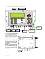
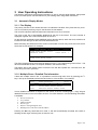
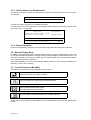
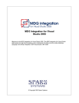
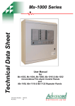
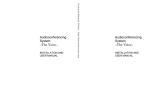
Product Data Sheet
Remote Terminals
Features:
•
Based around two core products, the Mx4010 Remote Display Terminal (RDT) and
the fully functional Mx-4020 Remote
Control Terminal (RCT).
•
Both remote terminals utilise the same
graphical LCD user interface that can be
found on the Mx-4000 series fire panels
and are based upon the same advanced,
flash based, microprocessor technology.
•
All Mx-4000 series panels and remote
terminals can communicate over the
same 2-core network cable.
•
Integral network interface incorporating a
special screen termination to prevent
mains frequency earth-loop currents
flowing between network nodes.
•
The ‘Ad-NeT’ network operates as a true
peer-to-peer system with full cross panel
reporting, control and cause and effect
functionality of up to 1000 zones.
•
The
display
information
is
fully
programmable by individual zone or
sector and can display any combination
of fires, faults, pre-alarms or plant
alarms. E.g. can display all information in
its own sector, but only show fire signals
from other sectors of a building.
Document Number:
Revision:
680-029
03
•
Both remote terminals incorporate
buzzer mute, view, enable/disable and
test facilities with dedicated system and
navigation keys for simple user control.
•
The RCT has additional sector based
control keys for Evacuate, Silence,
Resound and Reset, which allows other
networked
panels
to
selectively
respond to controls as programmed.
E.g. on a site with multiple buildings, a
user may be allowed to silence and
reset fires originating in their own
building. Fires originating from other
buildings are displayed but cannot be
reset.
•
Fully on-site programmable via onboard alphanumeric keypad or PC
configuration tools.
•
By using ‘flash memory’ and an
advanced graphical display the remote
terminals can be easily configured to
operate in virtually any language, with
any character set and allows for the
installer’s logo and company details to
be displayed on the LCD display during
normal operation.
ELECTRONICS LIMITED
Sales Order Parts:
Options:
Mx-4010:
(RDT) Remote Display Terminal
Mxm-008: Semi Flush Bezel
Mx-4020:
(RCT) Remote Control Terminal
Mxp-018: Access Enable Key-Switch
Mx-4010/FT: (RDT) with Fault Tolerant Network I/F
Mx-4020/FT: (RCT) with Fault Tolerant Network I/F
Item
Specification Details
Display
Backlit 240 x 64 graphical LCD
LED Indicators
3 Red (2 x Fire, 1 x Alarm), 1 Green (Power) & 7 Amber (Fault & System)
Keypad
Alpha Numeric Keypad, Navigation Keys & on-board buzzer mute facility
Controls (Mx-4020 RCT only)
System Keys for Reset, Silence, Resound & Evacuate
Key-Switch Input
Optional Level 2 Access Enable key switch
Power Supply Input
24 VDC, 150mA (/FT: 188mA) Operating range 15-30V
External Supply Monitoring
Monitored External Fault Input
Number of Fire Zones
1000 ‘Dynamix’
Serial port
1 RS232 Onboard for PC connection
Programming
Via on-board Keypad or PC running Windows Tools
Enclosure
Steel IP30
Cable Entry
20mm Knock-outs. 4 x top and 4 x rear
Colour
Beige (textured)
Size H x W x D mm
Enclosure: 218 x 300 x 44
Back Box only (when recessing): 218 x 300 x 30
Weight
2Kg
Metalwork Options
Semi Flushing Bezel, Special Finishes including Brass & Chrome
As our policy is one of constant product improvement the right is therefore reserved to modify product specifications without prior notice
Moorland House : Nelson Park : Cramlington
Northumberland : NE23 1WE
Tel: +44 (0)1670 707 111
Fax: +44 (0)1670 707 222
www.Advel.co.uk Email: [email protected]
ISO9001
ISO9001
Remote Terminals
Contents
1 INSTALLATION .............................................................................3
1.1
1.2
1.3
Identification of Components and Circuits................................................. 4
Mounting the Enclosure ............................................................................ 4
Electrical Connections .............................................................................. 5
2 COMMISSIONING .........................................................................5
2.1
2.2
2.3
2.4
2.5
Passwords ................................................................................................ 6
Zone.......................................................................................................... 6
Exit ............................................................................................................ 6
Setup ........................................................................................................ 6
Key-Switch Operation ............................................................................... 6
3 USER OPERATING INSTRUCTIONS ...........................................7
3.1
Automatic Display Modes.......................................................................... 7
3.1.1
3.1.2
3.1.3
3.1.4
3.2
3.3
Fire Display ................................................................................................................. 7
Multiple Zones / Detailed Fire Information .................................................................. 7
Faults, Alarms and Disablements ............................................................................... 8
Normal Operation........................................................................................................ 8
Manual Display Mode ............................................................................... 8
Control Functions (Mx-4020)..................................................................... 8
1 Installation
Only Trained service personnel should undertake the Installation, Programming and
Maintenance of this equipment.
This product has been designed to comply with the requirements of the Low Voltage Safety
and the EMC Directives. Failure to follow the installation instructions may compromise its
adherence to these standards.
Page 3 of 8
1.1 Identification of Components and Circuits
Enclosure
FIRE
Chassis Assembly
Function 1
Fault
Function 2
Disable
Function 3
Test
Function 4
Power
SU P P LY
Fire System
R e m o te C ontrol Term i nal
Reset
1
2abc
3def
Resound
4ghi
5j k l
6mno
Silence
7
8
9
E sc
0
pqrs
Evacuate
CPU Fault
R S 2 32
EXT RX T X
G ND
uP M O D E
RUN
PROG
K E Y S W IT C H
IN P U T
RESET
SWI TCH
tuv
w xy z
M en u
N E T W O R K -I N
TxNET
N E T W O RK - O U T
R xNET
Earth Lead
From Lid
24V DC
Supply
FLT
Input
Software
Upload
Header
Ad-Net Network
In / Out
Key-Switch
Input
1.2 Mounting the Enclosure
First, remove the enclosure cover,
which is held in place by tamper
resistant hexagon key screws.
These require the use of a 2.5mm
Allen Key.
Remove the two screws securing
the chassis on which the display
and all the electronics are
mounted. Put the chassis to one
side, observing normal anti-static
precautions.
226mm
35mm
17mm
Earth Termination
Points x4
Back Box Fixing
Points x4
Cable Anchor
Points x4
Remove the required knockouts
for the incoming supply/earth and
the network data cables.
Fix the unit to the wall using the
mounting holes in each corner of
the back box.
Recommended
Knockout Usage
Page 4 of 8
Power
IN
Power
OUT
Network
IN
Network
OUT
172mm
1.3 Electrical Connections
Fit the cable glands for the incoming supply
and network data cables. Cable Anchor Points
are provided in the rear of the back box to
enable these cables to be securely fastened
using tie-wraps.
Connect the incoming power supply earth wire
to the earth stud in the back box.
Re-fit the chassis plate. Connect the 24V DC
supply feed to the SUPPLY +24V and 0V
terminals.
Note the power supplied used MUST BE
designated a Safety Extra Low Voltage (SELV)
supply.
A stand-alone power supply with clean-contact
fault output contacts can be monitored by
taking them to the “FLT-INPUT” connections on
the left hand terminal block. A 10K series
resistor should be connected to the relay
terminals. If fault monitoring is not required a
10K resistor should be left in the “FLT-INPUT”
terminal block.
Please refer to document 680-027 for more
detailed information on the Ad-Net network.
All electrical wiring installation work should be
carried out in accordance with the code of
practice applicable in the country of installation.
To maintain electrical integrity of the SELV
wiring on the DC Power and Communications
lines all SELV wiring should be segregated
from any LV mains wiring and be wired using
cable with insulation suitable for the application.
To minimise the effects of EMC interference all
data wiring circuits should be wired with a
twisted pair of conductors with a cross sectional
area suitable for the loading conditions.
In areas where cabling may come into contact
with high frequency interference, such as
portable radio transceivers etc. the data wiring
cable should be of a twisted pair construction
within an overall screen. Cable screens must
be terminated as described in the text opposite.
Connect the 2 core twisted pair network data
cable to the A and B terminals.
Connect the data cable screen to the network
SCN terminals. Note that special screen
termination circuits are included on the circuit
card to prevent mains frequency earth-loop
currents flowing between network nodes. The
data cable screen MUST NOT be connected to
any other earth point.
NB: Minimum / Maximum cable size for all
connections is limited to 0.2mm² / 2.5mm² (2414AWG).
2 Commissioning
All commissioning items are accessed by using the navigation keys and selecting the appropriate
item from the commissioning menu. Wherever possible the menus have been chosen to follow a
similar format to the MX fire panels.
[Commission Menu 1]
PASSWORDS
PC-CONFIG
ZONE
SETUP
EXIT
VIEW
The steps needed to configure the remote terminal are as follows: a) Enter network and service details from SETUP
b) Use the PASSWORD option to enter any custom passwords.
c) Use the ZONE option to enter the text corresponding to the terminal’s zone.
EXIT from commissioning into normal Level 2 operation. Check network.
Page 5 of 8
2.1 Passwords
Allows the passwords used for level 2 and level 3 accesses to be changed. The remote terminal
uses the same defaults as the fire panel.
2.2 Zone
Shows the text corresponding to the terminal zone. Pressing the Tick key allows the text to be
changed. It is recommended that text be chosen that describes where the terminal is in the
building, so that in the event of the EVACUATION key being used, all panels and terminals on the
network will show where the fire has been detected.
This text will also be displayed if the terminal’s monitored power supply FLT input goes open or
short circuit.
2.3 Exit
Once commissioning is completed, use Exit to return the terminal to normal level 2 operation. It is
recommended that once at level 2, the VIEW/NETWORK option be used to check the network
configuration (see network document for details).
2.4 Setup
Basic network configuration must always be performed first: -
[Setup]
THIS NETWORK NODE
NEXT NETWORK NODE
TERMINAL ZONE
SERVICE NUMBER
:
:
:
:
2
3
98
01234 567890
“THIS NETWORK NODE”
- The network node address for this terminal.
“NEXT NETWORK NODE”
- The address of the next network node
“TERMINAL ZONE”
- The zone number used to identify this terminal – select a number
that is not being used by the fire panels or other terminals.
- (The text description of the zone is entered from the “ZONE”
option off the commission menu)
“SERVICE NUMBER”
- Numbers/Text displayed under fault conditions.
“COMPANY LCD LOGO”
- Toggle on/off as required
“PROGRAM ID”
- Displays the full version number of the installed software.
“CONFIG DATA
- Shows checksum corresponding to terminal configuration
- (Moving to the right gives option to erase all configuration data)
2.5 Key-Switch Operation
As an alternative to passwords, a key switch can be used to change between Level 2 and Level 1
access on the MX4020 by connecting a key switch to the “KEY-SWITCH INPUT” terminals.
This input is pre-defined to inhibit the RESET, SILENCE, RESOUND and EVACUATE control
functions when the terminal is at access level 1.
Page 6 of 8
3 User Operating Instructions
The following instructions give general information on how to use the panel displays. Always take
into account the specific Fire Procedures for your building when using these instructions.
3.1 Automatic Display Modes
3.1.1 Fire Display
The primary function of this remote terminal is to indicate the location of any fires that may occur.
You do not need to press any keys to see where a fire has started.
Twin red LED indicators will illuminate when information on a fire is received.
The origin of the fire is automatically displayed at the top of the screen. The zone number is
displayed, together with a full text description of the zone.
On the third line the display shows additional text to describe where, within the zone, the device is
located and also the type of device that has detected the fire.
Below a dividing line drawn across the screen is information on how many zones are in fire and to
where the fire has spread. For example:
.
FIRE STARTED IN ZONE 0001
Scroll R
SOUTH WING GROUND FLOOR
ENTRANCE LOBBY
<CALL POINT >
[
2 Zones in Fire][Last Fire in Z0057]
SOUTH WING FIRST FLOOR
The above example shows a fire that has started in zone 1, in the South Wing Ground Floor. The
device that detected the fire is a call point situated in the entrance lobby.
The bottom part of the display shows us that the fire has also spread into a second zone, the
South Wing First Floor (zone 57).
3.1.2 Multiple Zones / Detailed Fire Information
If there are multiple zones in fire, it is possible to scroll through each zone by pressing the ↑↓
keys. The top of the display will then list each zone in a fire condition. For example:
Zone
0001
0057
0082
FIRE-LOCATION
More >
SOUTH WING GROUND FLOOR
.
SOUTH WING FIRST FLOOR
SERVICE BLOCK PLANT ROOM
If more, detailed information is required on the source of the fire, scrolling right (→ key) will give
detailed information on the fires within the zone. For each detector in fire the following information
is available: •
•
•
•
•
•
Device location text
Loop number
Address number
Device Type
Detector Analogue/Digital value
Building Sector and Network Node address
Pressing the Esc key terminates this mode. It will also automatically terminate and revert to
showing the fire origin if the keys are not used for 15s.
Page 7 of 8
3.1.3 Faults, Alarms and Disablements
A summary of all faults, alarms and disablements present is shown at the bottom of the screen.
For example:
.
3 Zone With Disablements
More >
Scrolling to the right will give more, detailed information.
If a new event occurs, a full description of the detector and the nature of the event is shown at the
top of the screen. For example:
ZONE 0001
SERVICE BLOCK PLANT ROOM
GENERATOR SWITCHGEAR
.
PRE-ALARM
(TEMPERATURE)
1 Zone In Alarm
3 Zone With Disablements
More >
More >
3.1.4 Normal Operation
Under normal operating conditions, the terminal will simply state “Normal System Operation”.
3.2 Manual Display Mode
In addition to the automatic display functions described above, the terminal supports a full range
of manually selectable operations, including viewing, testing, disabling, enabling detectors etc. All
these are accessed by pressing the “Menu” key. For further details, refer to the MX-4000 Series
User manual (Document No. 680-015).
Note that the display will revert to the automatic display mode if no key has been pressed in the
last 60s (or 15s if a fire is present).
3.3 Control Functions (Mx-4020)
The following control functions are available at access level 2.
Reset
Press to reset from a fire alarm condition.
Resound
Press to resound any outputs that have been silenced
Silence
Press to silence the sounders / bells.
This also Mutes the internal buzzer.
Evacuate
Press to initiate a manual evacuation and sound the alarms.
All the above control signals are transmitted over the data network to the other terminals and fire
panels.
Page 8 of 8