1
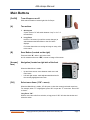
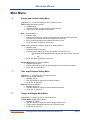
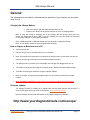
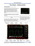
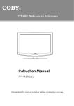
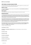
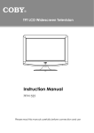
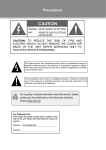
AES uScope Manual The uScope – Getting started Introduction (fw 4.19 October 1, 2011) The uScope! A single channel, pocket-sized, digital storage oscilloscope that ¡s small, quick, and powerful. Automotive presets get you going quickly. Ideal for the Flat Rater that wants the ultimate run and gun lab scope for pin point testing. Ideal for the student that is ready to start scope'n. The uScope is powered by an easy to use interface enhanced with automotive presets and reference waveforms. Put the power of the uScope in your hand (and shirt pocket). Secondary ignition, injectors, mass air flow, crank, cam, TPS, 02, CTS you name it it'll scope it. The uScope is also perfect for your low amp probe, secondary ignition pickup and pressure transducers. www.AESwave.com When you just need to run a quick test to verify the "signal" is working as the engineer intended, why spend time pulling out and setting up your "big boy Scope" when you can do it faster with the uScope? Copyright 2011 by Automotive Electronics Services, Inc. Page 1 AES uScope Manual First Time Use: Protective Film: The uScope is shipped with a protective film over the screen and the backside of the unit. Please feel free to remove the plastic film. Charge the battery: Charge your new uScope for at least 5 hours before first use. CAUTIONS Test Lead Connection The test lead connects to the uScope via an audio plug. The signal rides on the tip of the audio plug. If the tip of the test lead plug touches ground while the test lead is connected to a circuit, the circuit will short. o o Always connect your test lead to the uScope before connecting to a circuit. Always disconnect from the circuit before disconnecting from the uScope. Circuit Testing while Charging uScope It is not recommended to connect the uScope input channel to a circuit while the uScope is charging. Doing so may result in a ground loop that can destroy equipment and possibly endanger the user. Intended for DC Circuits The uScope is designed for use on DC circuits with a maximum voltage of 80 volts. o o Do not use the uScope for testing Line Voltage AC circuits. For DC circuits above 80 volts use a 10x probe. Contact AESwave.com or more information. Automotive Professionals The uScope is intended for use by automotive professionals with adequate training. o If you are not sure, ask! www.AESwave.com Copyright 2011 by Automotive Electronics Services, Inc. Page 2 AES uScope Manual o Ports, Connection and On/Off Button On/Off The on off switch is located at the bottom right of the unit. It is a slide switch. Test Lead Port The test lead connection is a 3.5mm stereo audio jack located at the top left side of the unit. When connecting, ensure that the plug is inserted to the base. Note: The 3.5 stereo audio jack port located at the bottom left of the unit is a signal generator. DO NOT USE THIS PORT WHEN TESTING AN AUTOMOTIVE CIRCUIT. USB to PC Connection and Charging Port The USB connector is a standard micro USB and is located in the middle left side of unit. This port is used for PC and uScope communication and for charging the uScope. Memory Card – microSD Card The uScope incorporates a microSD memory card. The card port is located in the center of the bottom side of the unit. Note that the electrical connection tabs face toward you for installation. Press the card in until fully seated. When properly installed the card will be just below flush. **Do not remove the memory card. Doing so may disable the ability to save and recall setups. www.AESwave.com Copyright 2011 by Automotive Electronics Services, Inc. Page 3 AES uScope Manual Main Buttons [On/Off] Turn uScope on or off Slide switch located on bottom right side of uScope [A] Two actions 1. Quick press A quick Press of “A” will switch between “stop” or “run” of the waveform. 2. Long Press Hold for 1 full second (or until the screen changes) to switch between the Main Menu or the Grid Value displays. For further instructions on saving an image or setup, refer to the manul. [B] Save Button (Located on the right) Press and hold “B”, while in grid value mode and in measurement menu “ME”, to save an image of the screen. [Arrows] face) Navigation (located on right side of the front When the Main Menu is visible: o o [OK] Up and down arrows: move between main menu and menu items Left and right arrows: make adjustments/selections for the currently highlighted menu item. Select menu Items (“OK” = menu) When the Main Menu is visible, “M” will open or close the currently selected menu item. For example, when “Tr” is highlighted, press “OK” to open the “Tr” menu item. Press “OK” to close it. Long Press “OK” When a menu item calls for a selection, a long press of “OK” will close the window and select the action. www.AESwave.com Copyright 2011 by Automotive Electronics Services, Inc. Page 4 AES uScope Manual Quick Start - How To: Charge the battery: Charge your new uScope for at least 5 hours before first use. Waveform Capture using a PreSet: All presets are stored and loaded onto the SD card. Turn on the uScope by sliding the switch located on the bottom right of unit. 1. Use the UP | DOWN arrow keys and highlight the “PS” (PreSets) menu item. 2. Press “OK” and the menu will open. 3. Use the UP | DOWN arrow keys to highlight the desired preset “Group.” a. Sensors, Actuators, Amp, Ignition, Charging, User Set Ups 4. Press the LEFT | RIGHT arrow keys to select the desired preset in the “Group“. 5. Press and Hold the “OK” button to activate the preset. 6. Connect your test leads and fine tune time voltage and trigger adjustments if desired. 7. Note: To select Auto Setup, highlight Auto Setup, and press & hold “OK” to activate it. Waveform Capture not using a PreSet: 1. 2. 3. 4. 5. Turn on the uScope by sliding the switch located on the top right of unit to the right. Use the UP | DOWN arrow keys and highlight the “Tr” (Trigger) menu item. Press “OK” and the menu will open Use the UP | DOWN arrow keys to highlight the “Tr” Mode (Trigger Display Mode) Menu item. Use the LEFT | RIGHT arrow keys to select AUTO. Note the prompt located in the top left of the screen. a. AUTO trigger type will allow the uScope to update the screen regardless of other trigger settings. This is a great first step to get the signal on the display. Reference chart on page 11. 6. Press “OK” to exit the menu 7. Connct test leads to the signal. 8. If the signal is to short or too tall: a. Use the UP | DOWN arrow keys and highlight the “.V” menu item. b. Press “OK” and the menu will open c. Use the UP | DOWN arrow keys and highlight “V/Div” d. Use the RIGHT arrow key to make the waveform taller. Use the LEFT arrow key to make it shorter. e. Press “OK” to exit the menu Continued…. www.AESwave.com Copyright 2011 by Automotive Electronics Services, Inc. Page 5 AES uScope Manual 9. To see more of the signal or less of the signal: a. Use the UP | DOWN arrow keys and highlight the “.T” (Time Settings) menu item. b. Press “OK” and the menu will open c. Use the UP | DOWN arrow keys and highlight “T/Div” d. Use the RIGHT arrow key to go to a faster time setting showing less time of the signal but in greater detail – like a magnifying glass. For example, see one injector pulse instead of three. e. Use the LEFT arrow key to go to a slower time setting showing more time of the signal but in less detail. For example, display three injector pulses instead of one. f. Press “OK” to exit the menu 10. To stablize the signal: a. Some signals can not be stablized. For example, a square wave that has a unique ID such as a crank sensor. Other signals are easy to stabalize. In either case follow these procedures: b. Use the UP | DOWN arrow keys and highlight the “Tr” (Trigger Settings) menu item. c. Press “OK” and the menu will open. d. Use the UP | DOWN arrow keys to highlight the “Tr” Level (Trigger voltage level) Menu item. e. Use the LEFT | RIGHT arrow keys to set the trigger level. The LEFT arrow key moves the trigger level down and the RIGHT key moves the trigger level up. Note: the Yellow dotted horizontall line in the display indicating the selected level. f. Note: When “Tr” level menu item is selected, The numerical value of the Trigger will be displayed on the top right of the screen. g. A good technique for beginners is to move the Yellow Dotted line level indicator above the signal. Then move it down and note the changes in the display of the waveform. i. Rules of thumb: 1. For repetitive signals that do not have a unique spike that reaches above or below the repetitive portion of the signal, such as a square wave, just place the trigger level within the center 1/3 of the signal. Leave the TRIGGER MODE on AUTO or NORM. 2. For signals that do have a unique charactoristic such as an injector or ignition place the TRIGGER LEVEL along a unique portion of the signal such as the rising edge of the spike or a falling edge use TRIGGER MODE on NORM to stabalize. One more helpful adjustment is to set the TRIGGER SLOPE to positive or negative. (In the “TR” menu highlight “TR.” SLOPE and use the LEFT | RIGHT arrow key to set the SLOPE. www.AESwave.com Copyright 2011 by Automotive Electronics Services, Inc. Page 6 AES uScope Manual Switching between MENU and Grid Values Display with Grid Values Display with Menu To switch between GRID VALUES and the MAIN MENU press and hold the “A” button for approximaely .5 seconds. (Please note: Tapping the “A” button for less than .5 seconds will hold the signal) www.AESwave.com Copyright 2011 by Automotive Electronics Services, Inc. Page 7 AES uScope Manual Main Menu “.V” Voltage and Vertical setting Menu Highlight the “V.” menu item and press “OK” to open the menu. V/Div (Voltage per division setting) Highlight V/Div Use LEFT/RIGHT to select desired Volts per division Press “OK” when complete to close menu Gnd (Ground position) Highlight “Gnd” Use the LEFT/RIGHT to move the vertical position of the waveform. Note: that left arrow moves waveform down and right arrow moves it up. Note: The horizontal grid line will always reference 0 volts. Press “OK” when complete to close menu Invert (Inverts waveform on display, ideal for secondary ignition.) Highlight Invert Press LEFT/RIGHT arrow key Note: the bottom right of the screen will indicate if invert is on or off o The following will be displayed at the button right of the screen if invert is on: INV Press “OK” when complete to close menu Ref Vert Pos (Reference Vertical Position) Highlight Ref Vert Pos Use the LEFT/RIGHT to pick the desired position of the reference waveform. Press “OK” to exit the menu “.T” Time and Horizontal Setting Menu Highlight the “.T” and press “OK” to activate the menu. T/Div (Time per division Settings) Highlight “T/Div” Use LEFT/RIGHT to select the time division setting Press “OK” to exit menu Horz Pos (Horizonal Postion) Highlight “Horz Pos” Use LEFT/RIGHT to select the desired Horizontal Position Press “OK” to exit menu “Tr” Trigger and Display Mode Menu Highlight the “Tr” and press “OK” to activate the menu. Tr. Disp Mode (Trigger Display Mode) Highlight “Tr.” Mode Use LEFT/RIGHT to select the desired trigger display mode Trigger mode is indicated at the top Left of uScope screen Press “OK” to exit menu www.AESwave.com Copyright 2011 by Automotive Electronics Services, Inc. Page 8 AES uScope Manual Tr. Level (Trigger Volt Level) Highlight “Tr.” Mode Use LEFT/RIGHT to select desired position of the Trigger level Left moves the trigger level down and right moves it up. Note: horizontal yellow trigger level indicator trace. Press “OK” to exit menu Tr. Slope (Trigger Slope) Highlight “Tr” Slope Use LEFT/RIGHT to select Trigger Slope Trigger Slope will be indicated by a yellow or red arrow just to the right of the trigger mode at top left of the uScope screen Note: When the trigger is red, this indicates the trigger is out of range. Press “OK” to exit menu Tr. Window (Trigger Window) Highlight Tr. Window Use LEFT/RIGHT to select trigger window. LEFT makes the window smaller and RIGHT makes it larger (vertically). Trigger window is indicated by the orange horizontal cursors Press “OK” to exit menu Tr HPos (Trigger Horizontal Position) Highlight HPos Use LEFT/RIGHT to select the trigger horizontal position. Press “OK” to exit menu “PS” Automotive Presets Menu (memory card must be inserted) Select the “PS” menu item and press “OK” to activate the menu. Use UP/DOWN to select preset type Use LEFT/RIGHT to scroll through different preset setups. Press and hold “OK” to load select preset. Screen will blink after loading preset and the preset name will be fixed in the top right of the screen. Press “OK” to exit the menu User Setups Please reference the user’s manual for more information. Show/Hide Ref Use UP/DOWN to highlight the menu item Use LEFT/RIGHT to toggle reference waveform on and off Press “OK” to exit the menu “SD” Save Waveforms, Setups, Configuration and Images on SD Card Highlight the “SD” menu and press “OK” to activate the menu. Note: SD card must be present in uScope. Save as image (BMP) Highlight the “save as image” menu item. Use LEFT/RIGHT to select file number to save. Note: filename at top right of screen. www.AESwave.com Copyright 2011 by Automotive Electronics Services, Inc. Page 9 AES uScope Manual Press and hold “OK” button until prompt changes to the next numerical file number - located in top right of screen. Press “OK” to exit the menu Save to USER file Highlight “Save to user file” Use LEFT/RIGHT to select file number to save. Note: filename at top right of screen. Press and hold “OK” button until prompt at the top right of screen changes the file number. Press “OK” to exit the menu “CR” Cursor Values “ME” Highlight the “CR” menu using the UP/DOWN arrow keys and press “OK” Use UP/DOWN to Highlight the desired cursor (Cursor V1, V2, T1 T2) Use LEFT/RIGHT to adjust cursor location. (Note: The cursor values are located on the bottom left of the screen) To turn cursors off. o Highlight either V1-V2 (vertical cursors) or T1-T2 (time cursors). o Use LEFT/RIGHT to toggle between ON/OFF. Press “OK” to exit menu Measurements Highlight the “ME” menu and press “OK” to activate the measurements value. To turn off measurement values. Use UP/DOWN and select “Enable On/OFF” Use LEFT/RIGHT to toggle between ON/OFF Press “OK” to exit menu “OP” Options Highlight the “OP” and press “OK” to activate the menu. Probe Cal (Probe Calibration) Highlight Probe Cal At the top right of the screen, the uScope will specify what attenuation setting you are currently on (Note: 10x does not change anything within the scope other than the voltage settings will be 10x larger – 1volt per division will read 10 volt per division. Use the LEFT/RIGHT to pick the desired attenuation. Press “OK” to exit the menu Sample Speed Use LEFT/RIGHT to toggle between Normal screen update and PEAK to PEAK mode. (Peak to Peak mode is started by default.) Press “OK” to exit the menu Grid Intensity Use LEFT/RIGHT to adjust the brightness of the graticule lines. Press “OK” to exit the menu SigGen Freq (Connect leads to the frequency generator for this option) This refers to the built in Frequency generator Use Left/Right to select the Frequency Press “OK” to exit the menu SigGen Duty (Connect leads to the frequency generator for this option) This refers to the built in Frequency generator duty Use Left/Right to select the Frequency percentage www.AESwave.com Copyright 2011 by Automotive Electronics Services, Inc. Page 10 AES uScope Manual Press “OK” to exit the menu Startup Menu On/Off Highlight “Startup Menu On/Off” using UP/DOWN Use LEFT/RIGHT to toggle between On/Off On = Menu items will show on startup Off = Menu items will be turned off and value mode will be turned on Press and hold “OK” to accept changes. You must now save your current settings as a custom startup. See below. Press “OK” to exit menu Set Custom Startup (Set current settings as default) Highlight “Set Customer Startup” using UP/DOWN Press and hold “OK” Message will appear on the upper right confirming the save “Save ok” Press “OK” to exit menu Reset Factory Default To reset your uScope to factory default settings. Use UP/DOWN to select “Reset Factory Default” Press and hold “OK” You will see a message flash on the upper right hand corner Calibrate Ground level calibration is automatically handled by the firmware. However, you can change the gain calibration of the scope. Please reference to your user manual for more information. www.AESwave.com Copyright 2011 by Automotive Electronics Services, Inc. Page 11 AES uScope Manual General: The following items are helpful in understanding the operation of your scope so you can get the most out of it. Charging the uScope Battery: Grab your uScope and USB cable included with your kit. Connect your uScope to any active USB port on a PC or charging station. Note: to verify the uScope is charging, turn on the uScope and look at the bottom left of the screen, you should see the word “USB.” If you see a battery icon, then the uScope is connected to an inactive USB port or not properly connected. Note: a USB receptacle or USB wall charger can also be used to charge the uScope. Note: Do not use the uScope on AC line signals while charging. How to Capture a Waveform onto a PC: Turn the uScope On Plug the uScope into an available USB port on a computer Note: The waveforms and presets are saved onto the uScope memory card. Never remove the memory card, doing so will interrupt some of the uScopes functions. The uScope memory card will act as removable mass storage once plugged into your pc. The folder can be accessed through my computer under “Devices with Removable Storage” The folder containing the waveform images is labeled “IMAGE” Note: The images are organized by image number, you will need to remember the image number. Note: IMAGE001- IMAGE016 are the reference waveforms. DO NOT delete the images. Firmware updates The uScope Firmware is updating on a regular basis with improved features and functions. To check for the latest version go to the uScope home: www.yourdt.com/uscope Note the firmware will only load and operate on the uScope designe by AESwave. http://www.yourdiagnostictools.com/uscope/ www.AESwave.com Copyright 2011 by Automotive Electronics Services, Inc. Page 12