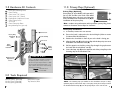
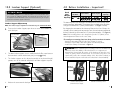
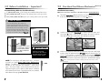
1
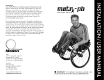
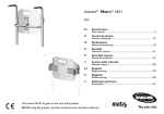
The original back must be returned to the dealer and will become
the property of Motion Concepts as a condition of processing the
warranty claim. All warranty claims must be made through the dealer
where the cushion was purchased. Except for express warranties made
herein, all other warranties of fitness or use for a particular purpose
are excluded. There are no warranties that extend beyond the
warranties provided above. Remedies for breach of this warranty are
limited to repair or replacement of goods. In no event shall damages
for breach of any warranty include any consequential damages or
exceed the original cost of the back.
Matrx®
ELITE
HEAVY-DUTY
BACK
IMPORTANT! The installation instructions contained in this
manual should only be carried out by a qualified technician.
TRD0320-01
INSTALLATION / USER MANUAL
WARRANTY
Every Matrx® Elite HD back is carefully inspected and tested to
provide optimum performance. Each back is guaranteed to be free
from defects for a period of 24 months from the date of purchase,
provided normal use. Should a defect in materials or workmanship
occur within 24 months of the original date of purchase, Motion
Concepts will, at its option, repair or replace it free of charge.
This warranty does not apply to punctures, tears or burns, nor
to the removable cushion cover.
Table of Contents
1.0
General Warnings
2.0
Hardware Kit Contents
3.0
Tools Required
4.0
Before Installation - Important!
5.0
Matrx Elite HD Installation
6.0
Disengaging the Matrx Elite HD
7.0
Removing the Cover/Care Instructions
8.0
Lateral Supports (Optional)
9.0
One-Hand Cord Release Mechanism (Optional)
10.0 Lumbar Support (Optional)
11.0 Privacy Flap (Optional)
SAFETY SYMBOLS:
Proper set-up and safe use of your Matrx Elite HD Back depends on your own
good judgement and common sense, as well as that of your provider, caregiver
and/or health professional. The following symbols are used throughout this
manual to identify warnings, cautions and important notes. It is very important
that you read and understand them completely.
CAUTION! Failure to heed the cautions in this manual may result
in damage to your Matrx Seating product.
WARNING! Failure to heed the warnings in this manual may result
in personal injury.
IMPORTANT! Important information to remember during installation
and set-up of you Matrx Seating product.
IMPORTANT! Please refer to the Wheelchair Owners/ Operators
Manual for additional safety information, warnings and cautions related to
the operation of your wheelchair.
Notes
1.0 General Warnings
WARNING!
DO NOT USE THIS PRODUCT OR ANY AVAILABLE OPTIONAL EQUIPMENT WITHOUT
FIRST COMPLETELY READING AND UNDERSTANDING THESE INSTRUCTIONS AND
ANY ADDITIONAL INSTRUCTIONAL MATERIAL SUCH AS OWNER’S MANUALS,
SERVICE MANUALS OR INSTRUCTION SHEETS SUPPLIED WITH THIS PRODUCT OR
OPTIONAL EQUIPMENT. IF YOU ARE UNABLE TO UNDERSTAND THE WARNINGS,
CAUTIONS OR INSTRUCTIONS, CONTACT A HEALTHCARE PROFESSIONAL, DEALER
OR TECHNICAL PERSONNEL BEFORE ATTEMPTING TO USE THIS EQUIPMENT OTHERWISE, INJURY OR DAMAGE MAY OCCUR.
ACCESSORIES WARNING
Invacare products are specifically designed and manufactured for use in
conjunction with Invacare accessories. Accessories designed by other
manufacturers have not been tested by Invacare and are not recommended
for use with Invacare products.
INSTALLATION WARNING
The procedures in this manual should be performed by a qualified technician.
After any adjustments, repair or service and before use, make sure that all
attaching component parts are secure.
DO NOT install the Invacare Matrx Elite assembly onto back canes with an
outside diameter greater than 1-inch or less than 3/4-inch. Otherwise, injury
or damage may occur.
The mounting position of the Invacare Matrx Elite is directly related to the
chair's stability. When the Invacare Matrx Elite is added to a TILT and/or
RECLINING chair, it may cause a decrease in the chair's stability. It may be
necessary to reposition the FRONT CASTERS, REAR WHEELS, BACK ANGLE,
TILT-IN-SPACE, RECLINE POSITION and/or SEAT DEPTH before use. Use
extreme caution when using a new seating position.
When a Matrx Elite is added to a TILT and/or RECLINING chair, a RIGIDIZER
BAR or CROSSBAR must be present to stabilize the back canes.
Ensure the Invacare Matrx Elite is properly secured to the wheelchair before
using. Otherwise injury or damage may occur.
16
WARNING!
Skin condition should be checked very frequently after the installation of any
new seating system.
Your therapist and physician should be consulted if you have any questions
regarding individual limitations and needs.
Working with your therapist, physician, and equipment supplier is the best way
to assure that a seating choice matches your individual needs.
As the needs of the individual become more complex, the seating evaluation
becomes more important.
1
2.0 Hardware Kit Contents
11.0 Privacy Flap (Optional)
2
2
2
2
6
6
2
2
4
Privacy Flaps (Optional):
-
Heavy Duty Mounting Plates
Cane Clamps
Cane Inserts 7/8” (22mm)
Cane Inserts 3/4” (19mm)
Depth/Recline Adjustment Screws
Cane Clamp Screws
Set Screws
Cane Clamp Nut Plates
Long Mounting Pins (optional)
Privacy flaps (1) are available (sold separately*)
for use with our Elite series backs. Each Matrx
Elite HD back comes with a pre-sewn loop strip
across the bottom rear of the back cover (B) for
installation of the privacy flap.
A
1
D
E
*Note: to obtain sizing information and/or purchase a privacy flap, please
contact our Customer Service Dept. for assistance.
Privacy Flap Installation:
Cane Insert
Heavy Duty
Mounting
Plate
Cane
Clamp
Nut Plate
Cane
Clamp
Screws
!
2
2.
Ensure the back is adjusted to the desired height. (Refer to section
5.0 Matrx Elite HD Installation).
3.
Position the wheelchair in front of you so the back is facing you.
4.
Align the hook strip (A) on the privacy flap with the loop strip sewn on to
the bottom rear of the back cover (B).
5.
Pull the opposite end of the privacy flap through the gap between
the back and the wheelchair seat (C).
6.
Secure the loop strip (D) on the opposite end of the privacy flap to the
fastening strip on the wheelchair seat*.
B
PLEASE NOTE
If any of the above hardware is missing or
misplaced, please contact your local
Motion Concepts Representative to obtain
the necessary replacements parts, or you
may contact our Customer Service Dept.
directly for assistance.
Canada: 905-695-0134
USA: 716-447-005
3.0 Tools Required
Wrench (22mm): (provided)
Hex Key (5mm): (provided)
Hex Key (2mm): (provided)
If installed, remove the seat cushion.
Cane Clamp
Set Screw
Depth/ Recline
Adjustment
Screws
1.
D
C
C
1
Utility Knife/Scissors
Tape Measure/Ruler
REAR VIEW
E
C
FRONT VIEW
*NOTE: The fastening strip pre-installed on the wheelchair seat pan or sling
upholstery may be either a hook strip or a loop strip. It may be necessary to install
the double sided hook strip (E) onto the privacy flap to secure it to the seat.
15
4.0 Before Installation - Important!
10.0 Lumbar Support (Optional)
!
PLEASE NOTE
Back
Matrx Elite
Back Widths
Size/
HD Back
Weight
21",22”,23”,24"
Capacity PBE-wwhh-HD
The Lumbar Support is a pre-fabricated foam insert that provides lower
back support for additional comfort. The position of the lumbar insert can
be adjusted inside the Matrx Elite cover (see instructions below), or it may be
removed if no lumbar support is desired.
53 ,56,58,61cm
Lumbar Support Adjustment:
Note: The lumbar support adjustment is illustrated using the Standard Elite Back
1.
To access the Lumbar Support, open the outer cover at the bottom rear
of the back pan.
unfasten velcro to
access the Lumbar
support/ insert
A.
2.
The foam lumbar support/ insert is installed inside the Elite cover between
the foam back cushion and the back pan (see image B. below)
3.
The lumbar support can be adjusted manually to any desired height/
position, or it can be removed completely if no lumbar support is required.
lumbar su
pport
14
41"cm, 51cm
227 kg
By changing the orientation of the Mounting Plates on the Cane Clamps, the
assembly can be reconfigured* to provide a more forward mounting position for
the back if desired (up to a maximum 2.5” (64mm) forward offset - see Figure 2)
WARNING! When establishing the mounting position for the Matrx Elite
HD back, ensure the stability of the wheelchair is not compromised.
Adjusting the forward and aft position of the backrest will alter the user’s
center of gravity within the wheelchair. A recessed back position can
significantly reduce the rearward stability of the wheelchair. Similarly, a
more forward back position will reduce the wheelchair’s forward stability.
Figure 1
Figure 2
Front of
wheelchair
Front of
wheelchair
r
ba rt
lumppo
su
adjust insert
as needed or
remove completely
Refasten the cover onto the back pan.
500 lbs
The Mounting Plates are shipped pre-assembled on the Cane Clamps in the
rearmost mounting configuration. This maximizes the seat depth on the wheelchair
seat (up to a maximum 2.5” (64mm) rearward offset - see Figure 1 below).
B.
4.
16" , 20"
*To reconfigure a mounting plate/cane clamp to the forwardmost orientation:
- detach the Mounting Plate from the Cane Clamp (3 screws);
- Rotate the Cane Clamp 180° and re-fasten it to Mounting Plate;
- Install Cane Clamp as illustrated in Figure 2.
Front
foam cush
ion
Weight
Capacity
Note: Each mounting plates is also designed to provide 1.5" (38mm) of fore
and aft adjustment relative to the cane clamp
Lumbar Support
foam cushion
Back Heights
C.
HD Mounting Plate in the
rearmost back position
(maximized seat depth).
HD Mounting Plate in the
forward most back position.
3
9.0 One-Hand Cord Release Mechanism(Optional)
4.0 Before Installation - Important!
Accommodating Different Sized Back Canes:
Installation Instructions:
w 1” (26mm) back cane - Cane clamps are installed without plastic inserts.
w 7/8” (22mm) back cane - Requires 7/8” (22mm) plastic inserts (provided)
w 3/4” (19mm) back cane - Requires 3/4” (19mm) plastic inserts (provided)
Note: The cord release mechanism is illustrated using the Standard Elite Back
!
1.
Thread the Nylon Cord through the holes in the latch mechanism at the top
of the left and right mounting plates (see image A. below.)
thread cord through
the latch mechanism
PLEASE NOTE
On some wheelchairs, there may be an
uneven seam along the back canes where a
smaller diameter tube is inserted into a larger
diameter tube. If the Cane Clamps must be
mounted over this seam, the plastic inserts
may be cut in half to allow the clamp to fasten
securely onto the back canes (see Figure 4).
Figure 3
A.
2.
Cane
Figure 4
Install the spring loaded Cord-Lock mechanism onto the nylon cord
(see image B. below). Press the button to open the lock mechanism
and slide the two open ends of the cord through the opening.
Clamp
tie a knot
using both
cord ends
Plastic Insert
#
The Plastic Insert may be
cut if the Cane Clamp is
secured at the junction
of 2 different diameter
back posts.
melt cord ends to
prevent fraying
HELPFUL HINT
Spray a small amount of
hairspray on the back
canes and on the inside of
the plastic inserts to create
a secure ‘no-slip’ bond.
NOTE: For wheelchairs with short back canes, it may be
necessary to install Posture Back Cane Replacements
(PBCR’s). The PBCR’s are designed to replace existing push
handles or cane extensions on standard 1” (26mm) back
posts. The Cane Clamps can be mounted directly onto the
replacement back canes in order to allow proper installation
of the Matrx Elite HD back. Cane Replacements are available
from Motion Concepts (part#-TRX2810).
3.
depress button
to open/adjust
d
Cor k
Loc
B.
With the back properly installed on the wheelchair, adjust the cord length
so that it hangs at approximately a 45° angle along the back pan (this will
allow the release mechanism to operate more effectively). If necessary, cut/remove
excess cord to eliminate any risk of entanglement. Once adjusted, combine
the loose cord ends into a single knot to prevent the cord-lock from slipping.
(Note: if the cord length was modified, carefully melt the ends of the cord to
prevent fraying)
PBCR
Matrx Elite
(installed)
45°
‘LIFT’ cord to
release back cushion
4
NOTE: Cord is shown installed on a Standard Elite Back
13
5.0 Matrx Elite HD Installation
8.0 Lateral Supports (Optional)
Instructions for Installing Lateral Supports:
1
Pull up the bottom of the cover (release velcro fasteners) to expose the
mounting slots/channels in the back pan.
2
Determine the desired mounting height/orientation for the lateral pads
(upper or lower mounting slot position).
3
If applicable, carefully bend the lateral support(s) to the desired contour
(prior to installation).
4
Loosely install the lateral supports onto the
back pan using the hardware provided.
Note: hardware can be installed in either
orientation on the back pan (with backing
plates located on the inside or outside
of the back pan).
5
Adjust laterals to the desired
position via the mounting slots
on the backpan and via the slots
in the lateral support bracket.
Secure each lateral support into
place.
6
Re-attach the back cover via
the velcro fasteners.
(Mounting hardware
may be installed in
either orientation for
ease of installation)
WARNING! The installation hardware provided is high strength and tested
for durability. DO NOT substitute hardware. Use only the hardware supplied.
1
Remove existing wheelchair back upholstery (if applicable).
2
Establish the desired Mounting Plate set-up/configuration for the user
(per Section 3.0).
3
Loosen Cane Clamp screws (x3) and loosely install the cane clamp (with
mounting bracket) onto each back cane. (Install plastic inserts if required).
4
Starting on one side, position the Cane Clamp at the desired height on
the back canet and tighten the clamp screws enough to hold it in place.
(Clamps and set screws will be fully tightened after the back is installed
and all final adjustments have been made.)
5
From a fixed point on the wheelchair (e.g. seat frame/rigidizer bar) measure
the exact height of the installed Cane Clamp assembly, and install the
second Cane Clamp at the same height on the opposite back cane - see
Figure 5 below. Ensure the Cane Clamps/Mounting Plates are mounted
parallel with each other.
Figure 5
Lateral Support
Install Cane Clamps at equal heights on
back canes and parallel to each other
Lateral Support
Mounting Slots
Cane Clamps
3” (76 mm)
Lower
Mounting
Slots
12
Upper
Mounting
Slots
FRONT VIEW
REAR VIEW
(Wheelchair with Back Removed)
(cover removed)
5
5.0 Matrx Elite HD Installation
!
PLEASE NOTE
Additional upper and lower adjustment
slots are provided on the Mounting Plate
to allow alternate mounting heights if
obstacles are encountered. Using these
Alternate Mounting Slots will increase or
decrease the back height by 7/8" (22mm).
(note: these alternate slots will limit the
range of available depth and/or recline
angle adjustment).
6
7.0 Removing the Cover/Care Instructions
Upper
Adjustment
Slot
Carefully remove the cover by releasing the velcro hook and loop fasteners
along the top & bottom edge and inside of the back shell.
Heavy Duty
Mounting
Plate
8.0 Lateral Supports (Optional)
Lower
Adjustment
Slot
To install the Matrx Elite HD back onto the mounting plates:
Step 1: Slide the lower mounting pins into the hooked slots at the
bottom of each mounting plate (1). (see Figure 6).
Step 2: With the lower pins in place, lock/snap the upper mounting pins
into the latch mechanism at the top of the mounting plates (2).
WARNING! Ensure both latch mechanisms are fully engaged around
the upper mounting pins following installation.
Upper
Mounting
Pin
General Care and Cleaning: The cover may be easily wiped down with a
damp cloth when necessary. Before laundering the inner foam cushion must
first be removed from the outer cover. For specific laundering directions, please
follow the washing instructions provided with the cover.
Lateral Pads are available on the Matrx PB Elite Heavy Duty backs as an
option for additional lateral support. Lateral Pads are offered in small, large and
offset styles (see Figure 8 below). Mounting slots in the back shell and the lateral support brackets allow for adjustment both vertically and laterally. Upper
and lower mounting slots are provided on the back pan for an even greater
range of adjustment. (Refer to p.12 for detailed installation instructions).
Standard
Lateral
(small)
Standard
Lateral
(large)
Figure 8
Offset
Lateral*
Figure 6
3”
(76 mm)
2
3”
(76 mm)
FRONT VIEW
*note: offset laterals may be mounted to the back pan in either orientation (as shown) to provide extended support
!
1
Lower
Mounting
Pin
6
PLEASE NOTE
Lateral Supports may be further customized by carefully bending** the
lateral to a more desirable contour/ position for the client.
**Important! To prevent damage to brackets and hardaware, always remove the
lateral supports from the back pan prior to bending.
11
6.0 Disengaging the Matrx Elite HD
5.0 Matrx Elite HD Installation
To Disengage the Back from the Wheelchair:
7
Before proceeding with the final set-up, the mounting pins will require
adjustment to ensure the backrest is propely fitted/secured to the wheelchair.
Step 1: Simultaneously lift the release levers (left & right) to unlock the latch
mechanism (1) and release the upper pins from the mounting plates
(2). Refer to Figure 7 below.
!
PLEASE NOTE
(note: for backs equipped with the one-hand cord release mechanism, lift
cord upward to unlock/open the release levers -see Section 9.0: OneHand Cord Release Mechanism).
Step 2: Lift entire backrest up and forward to disengage the lower pins from
the lower slots in the mounting plates (3).
Upper
Mounting Pin
Figure 7
2
Matrx Elite HD backs are available in four widths: 21”(53 cm), 22”(56 cm), 23”(58 cm) and
24”(63 cm); and two standard heights: (16" (41cm) and 20" (51cm)). Due to variances that
exist between different wheelchair manufacturers, the depth of the mounting pins may
require some adjustment to properly fit the Matrx Elite HD back onto the wheelchair
back canes (see Step 8). Two sets of depth adjustable pins are supplied with every back:
Standard Pins (x4) and Long Pins (x4)*. Our standard pins come factory installed and
are suitable for most typical wheelchair configurations. Long pins are designed to allow
installation onto back canes that are up to 1" (25mm) wider than the width of the actual
backrest.
Example: 22" (56 cm) Matrx Elite HD fits:
22" (56 cm) wheelchair seat frame (back cane width) = Standard Pins
23" (58 cm) wheelchair seat frame (back cane width) = Long Pins
*NOTE: when exchanging mounting pins, the Pem-Nut Backing Plates (not shown)
must be re-aligned with the new mounting pins in order to complete the installation.
1
Matrx Elite HD
(rear view)
Release
Lever
3
Lower
Mounting Pin
Mounting
Pins (x4)
Adjustable
Pin Depth
WARNING! Extended Mounting Pin (EMP) Kits: Extended mounting pins
allow a back to be installed on back canes up to 2” wider than the back width. EMP
kits are only for use with our standard sized Matrx Elite backs (up to max. 300lb
(136kg) weight capacity). NEVER use EMP’s with the Matrx Elite HD back.
10
7
5.0 Matrx Elite HD Installation
5.0 Matrx Elite HD Installation
8
9
To adjust the mounting pins:
i) With the back secured in place on the wheelchair, determine the
amount of adjustment required for each mounting pin (see below).
ii) Remove the backrest from the wheelchair and use the wrench
provided to loosen each flange nut. (If necessary, replace the standard
mounting pins with long mounting pins).
iii) Adjust the mounting pin depth (clockwise to shorten/counter-clock
wise to lengthen) so that a minimum gap of 1/8" (3 mm) exists between the
top of the pin and the mounting plate. Re-tighten each flange nut to
secure the pins in place. (ensure pins do not rotate when tightening the
flange nuts- NEVER use loctite on mounting pin hardware).
WARNING! Ensure all flange nuts are fully tightened; Failure to do
so may cause damage/cracking in the back pan
Standard Mounting Pin
Verify that the overall fit and alignment of the back is correct (make
adjustments as needed).
10 Fully secure the Cane Clamp Screws onto both back posts, and tighten
the set screws to ensure the mounting plates do not slip or rotate.
11 To best determine the optimal depth & recline settings for the back, the
user should be seated in the wheelchair. While seated, loosen the depth/
recline screws on the mounting plates and adjust the back to the desired
depth and recline angle. Re-tighten all screws to lock the back in position.
Ensure that the depth/recline adjustment for the back is made
symmetrically* on the left & right mounting plates.
!
PLEASE NOTE
The vertical score lines on the mounting
plates are designed as a point of reference
to assist with symmetrical mounting (see
image below). Since the back can be
mounted in a rotated (reclined) position
if desired, it will not always be mounted
parallel with these vertical lines.
Optional Long Mounting Pin
(provided separately)
Mounting Plate
Matrx Elite HD
Back Pan
min.1/8"
(3 mm)
e
cor
es
Lin
S
Depth/Recline
Screws
.
NOTE: back cane not shown
Flange Nut
*Use score lines to
make symmetrical
adjustments on
the left and right
mounting plates.
WARNING! Improper pin set-up may cause damage to the back pan
and/or the mounting plates. Ensure sufficient spacing is provided between
the mounting plates and the mounting pins (a min. gap of 1/8" (3mm) is
recommended).
8
9