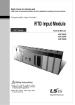
1
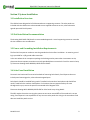
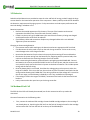
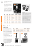
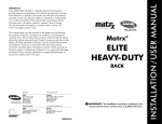
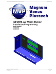
M-HACS-1112
Hybrid Air Compressor Manual
Unit 2 - 5550 Panorama Drive Surrey, BC Canada V3S 1B7
Surrey: 604-576-8333 Fax: 604-576-8233 www.ensolsystems.com
Hybrid Air Compressor Instruction Manual
Forward
Thank you for purchasing Ensol System’s Hybrid Air Compressor Package.
Please read through this manual before operating the unit as it contains particular start up,
shut down and disconnection procedures.
If you have any questions or concerns, contact Ensol at:
Ensol Systems Inc.
Unit 2 – 5550 Panorama Drive
Surrey, BC, Canada, V3S 1B7
Tel: 604-576-8333
Fax: 604-576-8233
Email: [email protected]
www.ensolsystems.com
M-HACS-1112
2
Hybrid Air Compressor Instruction Manual
Table of Contents
Section 1 – Quick Start-Up & Critical Maintenance .................................................................................. 5
1.1
Quick Start-Up Procedure......................................................................................................... 5
1.2 Critical Maintenance Schedule ....................................................................................................... 6
Section 2 – General Information .............................................................................................................. 7
2.1 Product Introduction...................................................................................................................... 7
2.2 Product Specifications.................................................................................................................... 8
Section 3 System Installation ................................................................................................................... 9
3.1 Installation Overview ..................................................................................................................... 9
3.2 Skid Installation Recommendation ................................................................................................. 9
3.3 Power and Grounding Installation Requirements ........................................................................... 9
3.4 Solar Panel Installation................................................................................................................... 9
3.5 Batteries ...................................................................................................................................... 10
3.6 Methanol Fuel Cell ....................................................................................................................... 10
3.7 Air Filter & Dryer .......................................................................................................................... 11
Section 4 System Operation................................................................................................................... 12
4.1 General System Operation ........................................................................................................... 12
4.2 PLC Program Operation................................................................................................................ 13
4.3 Solar System Operation ............................................................................................................... 19
4.4 Fuel Cell Operation ...................................................................................................................... 19
4.5 UN Certified Methanol Fuel Cartridges......................................................................................... 20
4.6 Operational States ....................................................................................................................... 22
4.7 Default Parameters of cutoff threshold ........................................................................................ 23
4.8 Startup and Shutdown Phases...................................................................................................... 24
4.9 Anti–Freeze Protection Mode ...................................................................................................... 25
4.10 Operation at the Device ............................................................................................................. 26
4.11 Service Fluid............................................................................................................................... 27
Section 5 Error Messages....................................................................................................................... 28
5.1 Error Classifications Ranges.......................................................................................................... 28
M-HACS-1112
3
Hybrid Air Compressor Instruction Manual
5.2 Error Types .................................................................................................................................. 28
5.3 Most Common Error Messages .................................................................................................... 28
Appendix A Drawings............................................................................................................................. 31
Appendix B Vendor Manuals ................................................................................................................. 32
M-HACS-1112
4
Hybrid Air Compressor Instruction Manual
Section 1 – Quick Start-Up & Critical Maintenance
1.1 Quick Start-Up Procedure
The following are steps for a quick start procedure. For a more detailed description of the package, PLC
and Fuel Cell operation and start up, please read through Section 4 of this manual.
1. Ensure the EFOY Pro Fuel Cells are in Automatic Standby or Charging mode.
2. Ensure all fuses are closed and breakers are set to ‘On’.
3. Ensure all manual ball valves internal to the compressor package are in the closed position.
4. Screw the puck style filter into the compressor inlet. Ensure that the desiccant air dryer is filled with
the desiccant beads and is properly closed.
5. Go to the Output Jogging page by pressing the ‘F3’ button on the PLC. Test each device individually
for operation by pressing their corresponding control buttons on the screen. If one device does not
seem to be working, check the fuses and wiring. If all three are functioning, proceed to step 6.
6. The next step will be to start the system. Before this is done, ensure that all tools and hardware are
removed from inside the package for safety reasons. Proceed to the Pressure Set page by pressing
the ‘F4’ button on the PLC. Set the pressure set point and the +/- set point value as required by the
system. Next go to the System Control page by pressing the ‘F2’ button on the PLC. Press the ‘Start’
button and the system will now be in operation.
7. Once the receiver is full, slowly open the two manual ball valves located on either side of the
desiccant dryer. This will allow the air to flow out to any externally connected instrumentation.
8. To shut down the system, simply go to the System Control page by pressing the ‘F2’ button on the
PLC, and press the ‘Stop’ button.
M-HACS-1112
5
Hybrid Air Compressor Instruction Manual
1.2 Critical Maintenance Schedule
The following are critical maintenance activities for the Hybrid Air Compressor Package:
1. The Swan Air Compressor recommends that the oil be changed after the first 50 hours of operation
and every 1000 hours thereafter. It is our recommendation that Mobil SHC 524 be used for this
application. SHC 524 is high quality, synthetic, shear stable hydraulic oil with a wide temperature
range and maximized anti-wear protection properties.
2. The desiccant filter is a Van Air Model ID15/SW in-line desiccant dryer designed to dry compressed
air. The SG-23 filter cartridge has a part number of 26-0888 and needs to be replaced once the
desiccant beads have changed from a blue to a pink color (as seen through the site glass).
3. The exhaust water collection tanks should be emptied or replaced on the same
schedule/requirement as the fuel cartridges. Empty fuel cartridges can be used for water collection.
4. Do not let the fuel cells run out of fuel. This could lead to the unit shutting down and failure of the
air compressor. In winter operating conditions, allowing the fuel cell to run out of methanol may
cause the unit to freeze, which may damage the device. Once frozen the fuel cell needs 24 hours in a
warm, dry environment before it can be restarted.
M-HACS-1112
6
Hybrid Air Compressor Instruction Manual
Section 2 – General Information
2.1 Product Introduction
The Ensol Systems Hybrid Air Compressor package provides clean, dry and reliable air to instruments
requiring pneumatic power (i.e. shutdown valves, control valves, pneumatic switches, pneumatic pumps
etc.).
Powered by a hybrid system of photovoltaic cells and DMFC’s (Direct Methanol Fuel Cell), these
packages are reliable even in the most remote and harsh environments.
The design philosophy is to use solar energy when you have it, with a methanol fuel cell as a back-up
when you don’t. This will provide you with 100% reliable power even in the darker months of winter.
M-HACS-1112
7
Hybrid Air Compressor Instruction Manual
2.2 Product Specifications
AIR COMPRESSOR SKID (ACS) SPECIFICATION SHEET
Model:
No. compressors
Max. volume output @ 0 psi
@ 100 psi
ACS-2224
1
221 Litres/min
166 Litres/min
Standard pressure range
Estimated due point
Volume of tank
Outlet line size
Nominal compressor motor power
Power sources
0 to 125 psig
-40°C
60 gallon
1/2" tube connection
3/4 HP
Methanol fuel cells & Photovoltaic
solar panels
Fuel cell model
Fuel cartridge
No. fuel cells
No. fuel cartridges
No. batteries
No. solar panels
Max. power output per solar panel
Charging power per day(1)
EFOY Pro 2200
M28 (28 L container)
2
2
8
6
235 W
4320 - 7050 Wh/day
Nominal DC voltage
Battery bank capacity(2)
24 V
300 Ah
Environmental design temperature
-40°C to +45°C
(-40°F to +113°F)
Recommended storage temperature
+5°C to +60°C
(+41°F to +140°F)
Dimensions L x W x H
1524 x 1219 x 1325 mm
(5 x 4 x 4.3 ft)
<2500lbs depending upon
configuration.
12 months
Weight (dry)
Warranty
(1)
(2)
M-HACS-1112
Values depend on # of solar panels and installation area’s solar insolation.
Depends on battery type and application.
8
Hybrid Air Compressor Instruction Manual
Section 3 System Installation
3.1 Installation Overview
The skid has been designed to be field mounted onto a supporting structure. The solar panels are
included with the skid but are to be mounted to user supplied structures on site, unless otherwise
agreed upon with Ensol Systems.
3.2 Skid Installation Recommendation
The drawing HACS-4400 -500, details a recommended approach. Actual supporting structures must take
the site conditions into consideration.
3.3 Power and Grounding Installation Requirements
The Ensol Air Compressor enclosure must be grounded at the site after installation. An exterior ground
lug is provided for a 2/0 ground cable connection.
In the case where the air compressor package is also being used to power other instruments on site,
please use the extra power connection terminals provided (these are terminals 5 and 6 on terminal strip
2). Please see drawing HACS-4400-601, 602 & 603 for details.
3.4 Solar Panel Installation
Since each site location will have varied methods of mounting Solar Panels, Ensol Systems does not
include panel mounting poles, unless otherwise agreed upon.
Solar Panels should be installed facing south if installed in the northern hemisphere and should face
north if installed in the southern hemisphere. For locations that may experience days of snow
throughout the year, ensure the panels are mounted with 0 degrees of tilt.
Please see drawing HACS-4400-601, 602 & 603 for Solar Panel Array wiring details.
The NEC requires that wires carrying the system current never exceed 80% of the conductor’s current
rating. Ensol Systems is not responsible for any incorrect solar panel wire sizing in the case where Ensol
does not install the panels on site.
M-HACS-1112
9
Hybrid Air Compressor Instruction Manual
3.5 Batteries
Sealed Lead-Acid batteries are provided to store the solar and fuel cell energy, and will supply the large
current draw for the intermittent operation of the compressor. Battery cables provide the link between
the batteries, equipment and charging system. Faulty connections can lead to poor performance and
terminal damage, meltdown or fire.
Batteries Inspection
• Examine the outside appearance of the battery. The tops of the batteries and terminal
connections should be clean, free of dirt and corrosion, and dry.
• If fluid is on the top of a gel or AGM battery this means that the battery is being overcharged
and the performance and life will be reduced
• Check battery cables and connections. Replace any damaged cables with a min. #6 AWG.
Tighten any loose connections.
Changing or Disconnecting Batteries
• Use extreme caution while working on the batteries and ensure appropriate PPE is utilized.
• First disconnect the solar panel array from the solar charge controller. Failure to do so may
cause damage to the solar charge controller.
• Next isolate the batteries from the electrical system by disconnecting all fuses and breakers.
• Disconnect the system wiring from the batteries first, beginning with the positive leads, then
continue to disconnect the remaining batteries from one another
• When reconnecting the batteries, please follow the wiring diagram HACS-4400-601. Connect
two batteries in series to provide the 24VDC. Do this for all sets of two, and then connect each
set in parallel. Lastly connect the electrical system to the bank of batteries. This includes power
wiring, and the fuel cell wiring.
• Once the battery bank is connected, check that the voltage going to the system is within the
range of 23-29VDC. If this is not the case, do not close any fuses or breakers and check that the
wiring matches drawing HACS-4400-601. If the wiring matches and the voltage still is not within
the correct range, test each battery individually to see if any are defective or damaged.
• If the voltage is within the range of 23-29VDC, reconnect all the loads via the fuses and circuit
breakers.
• Lastly reconnect the solar panel array to the charge controller.
3.6 Methanol Fuel Cell
The EFOY Pro Fuel Cells will already be mounted, but all their accessories still may need to be
connected.
Connect all accessories in the following order:
•
First, connect the methanol fuel cartridge. Screw the M28 cartridge adapter to the cartridge if
not already done so, then bring the fuel line from the fuel cell through the wall to the cartridge
and screw the fuel line from the fuel cell to the top of the M28 adapter.
M-HACS-1112
10
Hybrid Air Compressor Instruction Manual
•
•
Second, connect the exhaust tubing line to the EFOY Pro fuel cell’s exhaust port. This is a small
tube stub protruding just next to the fuel line. Connect the exhaust tube to the water collection
container.
Third, connect the wiring harness and remote to their respective ports. Ensure that the remote
is plugged into the ‘Remote’ RJ45 port and not the ‘Data’ port.
3.7 Air Filter & Dryer
The air compressors inlet filter is a puck shaped filter with a 3/4” Male NPT connector on the bottom.
This should be installed on the underside of the skid, screwed into the inlet port.
The desiccant air dryer may not have the desiccant filter preinstalled. Undo the dryer retainer, remove
the housing and replace the filter cartridge.
M-HACS-1112
11
Hybrid Air Compressor Instruction Manual
Section 4 System Operation
4.1 General System Operation
The Air Compressor System’s basic operation is quite simple. A hybrid system consisting of an array of
solar panels and of a methanol fuel cell (illustrated in Figure 1), will charge a bank of sealed lead-acid
batteries. This stored electrical power is then used to run the air compressor, PLC and whatever other
loads may be involved. A pressure transducer sends the pressure signal to the PLC, which will in turn
start the air compressor if the pressure falls below the pre-set pressure set point. The PLC will also
control anything else required for a safe, optimized operation.
Figure 1 – Hybrid System
The layout is set up for ease of operation and maintenance, but is also crucial for proper operation of
the equipment. The fuel cell is located in a separate compartment because it needs to stay above 5°C.
While operating, the unit will give off heat and will keep itself warm in the insulated compartment. If the
unit is not operating and the temperature surrounding it drops below 5°C, the unit will go into antifreezing mode which runs the unit sufficiently to keep itself warm.
If the surrounding area gets too hot, the thermostat will activate an input in the PLC to turn the exhaust
fan on. This fan will pull the warm air from the fuel cell compartment into the rest of the enclosure,
while pulling cool air from outside into the fuel cell compartment. This will maintain the fuel cell at an
optimal temperature, regardless of the outside temperature. It will also keep the rest of the equipment
reasonably warm during normal operation.
M-HACS-1112
12
Hybrid Air Compressor Instruction Manual
4.2 PLC Program Operation
For an in depth look into how the air compressor system works, you will need to understand how the
PLC program operates. This section will go through each page of the program, step by step, hopefully
giving a better understanding of its operation.
The Home Screen for the program, as seen in Figure 2, will allow you to jump to any of the stated
screens in the program. To return to the home screen at any time, press the ‘F1’ key on the bottom of
the PLC.
Figure 2 - Home Screen
M-HACS-1112
13
Hybrid Air Compressor Instruction Manual
The System Control screen is illustrated in Figure 3. This screen will allow the user to start the program’s
operation, and will also allow the user to completely shut down the system. In shut down mode, nothing
will run automatically, but the user will still be able to jog any of the outputs as seen in Figure 4. To jump
to this screen at any point in time, press the ‘F2’ button.
Figure 3 - System Control
M-HACS-1112
14
Hybrid Air Compressor Instruction Manual
Figure 4 displays the Output Jogging page. This page allows the user to test any of the outputs for their
operation, without having the system running. Note that it will not hold the output active, and will
return to a non-powered state once the user de-presses the button. To jump to this screen at any point
in time, press the ‘F3’ button.
Figure 4 - Output Jogging
M-HACS-1112
15
Hybrid Air Compressor Instruction Manual
Figure 5 displays the Pressure Set page. This page is used to display the current tank pressure and is
used to set when the compressor will turn on and off. The pressure PV value displays the current tank
pressure. The pressure set-point is the pressure at which the compressor will pump the tank up to, while
the on/off pressure is used to give the compressor some hysteresis. The on/off value is subtracted or
added to the set-point to give you your on and off pressure respectively.
For example, if the pressure set-point is set to 110 psi and the on/off pressure to 5 psi, the compressor
will turn on when the pressure drops below 105psi and will turn off when the pressure rises above
115psi. To jump to this screen at any point in time, press the ‘F3’ button.
Figure 5 – Pressure Set
M-HACS-1112
16
Hybrid Air Compressor Instruction Manual
The Pressure Alarms page is shown in Figure 6. This page is used to set high and low pressure alarms for
the tank. Each value can be configured to send alarms to an external control system if desired. By
default PAHH-700 is set to 150 psi and will shut down the system if the pressure rises to this level. The
remaining alarms by default are only warnings locally.
Figure 6 – Pressure Alarms
M-HACS-1112
17
Hybrid Air Compressor Instruction Manual
The Run Time page is shown in Figure 7. This page provides the compressors total run time, the run time
system the compressor was last service and the hours until the next service is required. The compressor
needs to be service every 1000 hours, which includes an oil change, belt check etc. Once the run time
has gone past the 1000 hours, a warning will come up telling the user that the compressor needs to be
serviced and a reset button will appear. Once the compressor has been serviced, the reset button
should be pressed. This will restart the service hours and remove the warning.
Figure 7 – Run Time
M-HACS-1112
18
Hybrid Air Compressor Instruction Manual
4.3 Solar System Operation
The solar system is comprised of two 130Watt solar panels. If possible, try to face the panels south
towards the sun. Since the panels are on the mast, the lighting system may need to be located on the
south side of the area desired to be lit, in order to have the panels face south.
4.4 Fuel Cell Operation
The SFC EFOY Pro fuel cell uses a catalytic process to directly convert methanol into electricity (see
Figure 8). The byproduct of this reaction is water, small amounts of CO2 and heat. To eliminate freezing,
the water must be collected internally. The collected water should be changed out at the point in time
that the fuel cartridge is replaced.
Figure 8
M-HACS-1112
19
Hybrid Air Compressor Instruction Manual
Since the EFOY Pro fuel cell is a ‘smart’ fuel cell, charging and monitoring to the batteries is handled
automatically (example in Figure 9). With the remote which is included, the user can view the charging
mode, battery voltage, charging current, system operating hours and firmware version, and can also
change the charging mode. By pressing the power button on the remote, the user can turn the system
off, put it in automatic or turn the system on for one charge cycle.
Figure 9
Ensol Systems has pre-programmed the fuel cell’s parameters for the installation location. If charging
voltage set points need to be altered, please contact Ensol Systems.
For a full description of the EFOY Pro fuel cell’s operation, please see the manual provided by SFC’s
document 101123_UM_EFOY_Pro_GB_v02.
4.5 UN Certified Methanol Fuel Cartridges
The EFOY Pro uses special plastic fuel cartridges to facilitate ease of use and transport:
•
•
•
•
The methanol fuel cartridges are UN certified containers certified for transport on cargo planes.
The containers are spill resistant and designed to withstand significant impact force.
Empty cartridges should be recycled.
28L cartridges are the largest available size and a cartridge adapter is required to use this
cartridge with the EFOY Pro fuel cell. DO NOT THROW AWAY THE CARTRIDGE ADAPTER!
M-HACS-1112
20
Hybrid Air Compressor Instruction Manual
•
The fuel cell methanol is ultrapure. Do not puncture the cartridge. To avoid contamination, do
not transfer residual methanol from an old cartridge to a new cartridge. DO NOT USE ANY
OTHER METHANOL SOURCE TO FUEL THE EFOY PRO! Impure/contaminated methanol will
severely degrade the performance and life of the EFOY and will VOID WARRANTY.
M-HACS-1112
21
Hybrid Air Compressor Instruction Manual
4.6 Operational States
•
Note that a minimal battery voltage of 9.0V or 18.5 V is required for the EFOY Pro to start.
M-HACS-1112
22
Hybrid Air Compressor Instruction Manual
4.7 Default Parameters of cutoff threshold
New charging strategy (firmware 9.20 since mid of August 2010):
•
•
•
•
•
Switch on voltage: 12.3 V (11.0 - 13.0 V)
Switch off voltage: 14.2 V (13.5 - 14.7)
Switch off current: 2 A / 4 A @ EFOY Pro 2200 (0.5 - 10 A)
Switch off time: 3 hours (0 - 5 hours)
This ensures full battery charging and maximizes battery life
M-HACS-1112
23
Hybrid Air Compressor Instruction Manual
4.8 Startup and Shutdown Phases
M-HACS-1112
24
Hybrid Air Compressor Instruction Manual
4.9 Anti–Freeze Protection Mode
•
•
•
•
•
•
•
Note that the Hybrid Light Tower is heavily insulated to ensure that the system works in cold
temperatures.
THE ANTI-FREEZE PROTECTION MODE WILL NOT WORK WITHOUT FUEL! Please ensure that the
fuel cell does not run out of methanol in freezing temperatures. If the fuel cell freezes, 24 hours
will be required for the fuel cell to warm back up and be returned to service.
The Anti-Freeze Mode will keep the EFOY Pro warm while the temperature is below 5oC (This
will work even when the unit is “OFF”).
Anti-Freeze Mode requires the connection to a faultless, adequately charged battery and fuel
cartridge.
Fuel consumption will be dependent upon external temperature differential. Weather,
insufficient insulation, ambient temperature and operating mode can have an impact on fuel
consumption.
The EFOY Pro does not give the produced energy to a fully charged battery in Anti-Freeze Mode.
Rather, the stack “burns” methanol and supplies the peripheries (pumps, etc…) to heat up the
system. The batteries will not be overcharged.
Startup temperature (when the Anti-Freeze Mode has not been activated) is 5 oC.
M-HACS-1112
25
Hybrid Air Compressor Instruction Manual
4.10 Operation at the Device
Remote Control:
M-HACS-1112
26
Hybrid Air Compressor Instruction Manual
4.11 Service Fluid
•
•
•
•
If service fluid is low the yellow light will turn on at the EFOY Pro and the message “Please refill
service fluid” will appear at the control panel display.
Normally, there is no need to add service fluid prior to the initial start-up.
Note that the fuel cell produces its own service fluid during operation. This is critical to the
function of the device. If the EFOY Pro is operated continuously at temperatures above the
acceptable operating range (45 oC), the service fluid will be expelled faster than it can be
regenerated and cause a failure. For this reason, it is critical that the thermostat and fan
provided with the Fuel Cell Power Package are maintained in working order and set at an
appropriate temperature.
Service fluid can be added by removing the exhaust line as pictured below.
M-HACS-1112
27
Hybrid Air Compressor Instruction Manual
Section 5 Error Messages
5.1 Error Classifications Ranges
•
•
•
•
•
•
•
10
20
30
40
50
70
80
Internal hardware or firmware issue - Contact Ensol Systems.
Fuel - Change the cartridge and reset.
Service Fluid - Add service fluid and reset. Check thermostat and fan function.
Environmental Issue – Temperature too high or too low to maintain function.
Battery - Battery voltage too high or low. Check connections. Check solar charge controller.
Reservoir - Internal fuel problem. Check fuel connections and reset.
System - Internal voltage or system error. Reset.
5.2 Error Types
•
•
•
•
•
•
A = Automatic reset (after error cause is remedied)
M = Manual user intervention required
F = Anti-freeze protection is possible from this error, if the error cause currently no longer exists
P = Permanent error (not resettable)
R = Reset required to restart system
W = Warning
5.3 Most Common Error Messages
•
•
•
•
12, 13, 14 - Failure due to blocking of exhaust or circulation pump defect.
32, 31, 30, 41 - Failure due to high surrounding temperature. Check installation and ensure air
circulation is adequate.
52-54 - Check battery (voltage too low) and/or battery connection problem
72, 76 - Failure in Methanol dosing or internal sensors. Possible issues in Methanol cartridge
because of fuel line.
M-HACS-1112
28
Hybrid Air Compressor Instruction Manual
Display
mes sage
Error code
error type
1
P
Please contact
service
Please contact
service
Please check
exhaust hose
Rem edial measur e
Potential error caus es
System configuration
incomplete
Repair by SFC required
Firmw are update failed
Se rious s ys te m error
Repair by SFC required
Stack damaged
10
P
15
P
13
A (1x / 30s )
R
F
Stack pow er output too low
14
A (1x / 30s )
R
F
Fluid le ve l se ns or de fect
17
R
F
11
A (1x /30s)
R
F
18
Please change
fuel cartridge
Error des cription
20
Empty fuel cartridge dete cted
(internal fuel sensor)
22
M
R
F
30
M
R
F
31
M
R
F
Interruption:
Surroundings too
w arm
32
A
F
Se rvice fluid le vel be low 40%
41
A
F
Te mparature to high (internal
se ns or)
Interruption:
Please defrost
device slow ly
40
A
M
Te mpe rature too low
(stack temperature sensor < 3 °C)
Please check
battery voltage
50
A
F
T
Batte ry voltage too low
(se nse line )
51
A
Batte ry voltage too high
(se nse line )
Please refill
service fluid
Please contact
service
Hardw are de fe ct
Press RESET (max. 3 attempts),
re pair required if error re occurs
Abnormal pow er difference
be tw ee n stack and output
Stack voltage too low
(error 11: during operation,
A (3x / 300s) error 18: during start-up)
R
F
M
R
F
Low s ervice fluid level
(error 30: <20%, error 31: <5%)
Solve potential error caus e,
then press RESET (max. 3 attempts)
Exhaust hose blocked,
not sufficient fres h air
Change fuel cartridge
(solve error cause)
then press RESET
Error caus es if fuel cartridge not
e mpty:
- Bad connection of fuel cartridge
connector (air leak)
- Dirty fuel cartridge connector
Add service fluid
(solve potential error causes)
then press RESET
- Fluid level measurement defect
-Ambient temperature to high (avoid
direct sunlight)
- Poor air ventilation in installation
space
Defrost unit
(ca. 24 h at room temperature)
- Anti-freeze protection did not w ork
(due to an error)
Batte ry voltage < 10,5 / 21 V ->
charge w ith battery charger
Solve e rror cause
(check battery and connections)
Batte ry voltage > 16,5 / 33 V ->
check external battery charger and
disconnect if necessary
Che ck connection to battery:
- Check battery cables
- Check battery fuses
A
Battter y voltage too low
(pow er line )
53
A
Batte ry voltage too high
(pow er line )
54
A
Batte ry voltage meas ure me nt
de fect
70
R
Error fuel re se rvoir se ns ors
73
R
75
R
80
R
83
R
Internal fue l s ensor defect
Re se rvoir error (e mptying time
too long)
Press RESET (max. 3 attempts),
Internal voltage re fe rence out of
re pair required if error re occurs
tolerance
DC/DC-Transfor mer de fect
84
R
A
P
M-HACS-1112
Test: disconnect exhaust
hose and press "Reset", if
fuel cell is now running the
exhaust hose is blocked
- Operation at high ambient
temperatures or insufficient cooling
air
Wait
(until temperature has dropped)
52
76
Note s
If the error pers is ts a repair is
re quire d
Circuit Board defe ct
Se lf tes t equipm ent
Se rious re se rvoir error
Perm ane nt error - repair re quire d
- Error 70 or error 72
re occurre d 3 time s
29
Hybrid Air Compressor Instruction Manual
Please check fuel
cartridge
connector
72
A
M
F
R
Re se rvoir error (re filling time
too long)
Solve potential error caus e,
then press RESET (max. 3 attempts)
Please install
Filter XT
Please contact
service
38
W
Filte r EFOY XT is rem ove d
ins tall Filte r
only EFOY 2200 XT
85
R
Filte r-Circuit-Board EFOY XT not
de tecte d
Pres s RESET (max. 3 attem pts),
re pair required if error re occurs
only EFOY 2200 XT
137
A
Filte r change confirme d
no action re quire d
only EFOY 2200 XT
139
M
Filte r change is displayed
change Filter EFOY XT
only EFOY 2200 XT
no display
information
90
A
Antifre eze mode s uccess fully
no action re quire d
Update: DO NOT
UNPLUG
BATTERY
99
A
Firmw are update is pe rforme d
not interrupt firmw are update
no display
information
140
A
Antifre eze mode not pos sible
fix othe r error
no display
information
172
A
no display
information
184
A
Firmw are corrupt
update required
w ithout
A
No connect or
Check battery
w ithout
no display
information
Please change
Filter XT
Error 72 w as once ignore d
- Firmw are problem (FW <9.11)
- Bad connection of fuel cartridge
connector (pumps air)
- Dirty fuel cartridge connector
Firmw are update
recommended (fixed w ith
FW 9.11 or higher)
another error is blocking the
antifre eze mode
no action re quire d
Se lf tes t equipm ent
succe ss fully
no action re quire d
trans fer de fective fir mw are
re pe ate firm w are -update
Re mote control has no
conne ction to fue l ce ll
Che ck connection, load battery if
necess ary
- Remote control is connected to
w rong port (Data Interface)
- Batter voltage < 8,5 V
- No communication (defect)
M-HACS-1112
30
Hybrid Air Compressor Instruction Manual
Appendix A Drawings
Drawing Number
HACS-4400-201
HACS-4400-500
HACS-4400-501
HACS-4400-601
HACS-4400-602
HACS-4400-603
M-HACS-1112
Description
Piping & Instrumentation Diagram
Recommended Installation Details
Enclosure Layout Details
Electrical System Wiring Schematic
PLC Wiring Schematic
Control Panel Backpan Details
31
Hybrid Air Compressor Instruction Manual
Appendix B Vendor Manuals
Manufacturer
ASCO
HORNER
SWAN
TRISTAR
VAN AIR SYSTEMS
M-HACS-1112
Description
PRESSURE TRANSDUCER
PROGRAMMABLE LOGIC CONTROLLER
AIR COMPRESSOR
SOLAR CHARGE CONTROLLER
DESICCANT AIR DRYER
Title
Instruction Manual
Instruction Manual
Instruction Manual
Instruction Manual
Instruction Manual
32