1
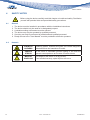
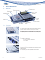
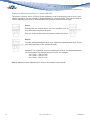
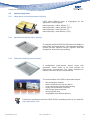
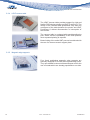
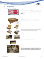
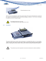
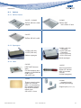
USER MANUAL Manual Fine-Pitch Stencil printer LPKF ProtoPrint® S Introduction 1Introduction Company name: Abbreviated name: Address: LPKF Laser & Elektronika d.o.o. LPKF d.o.o. Polica 33 SI-4202 Naklo Slovenia Telephone: Fax + 386 (0) 592 08 800 + 386 (0) 592 08 820 Internet: www.lpkf.si E-mail: [email protected], [email protected] Trade-mark: 1.1 ProtoPrint S LPKF ProtoPrint S is a precision manual stencil printer for professional fine pitch SMT prototyping and short run production. Precise vertical separation between the stencil and circuit board is guaranteed to meet the specifications of contact printing. This unique solution allows printing of 0,3 mm (12 mil) pitch. The printing table can be precisely adjusted in both x and y directions and rotation with the table either under the stencil, or in the service position using a test print screen. User Manual v1.03 Rev.: 29.05.2013 3 Introduction 1.2Warnings Copyright© 2010 LPKF d.o.o. Copying and distributing these instructions in their entirety or in part is only permitted by LPKF approval in writing. Note: Data can be altered without prior notice. Original Instructions LPKF is not liable for any damage occurring due to improper use of these instructions. The owner of the LPKF device is obligated to: • • • • • • Ensure that the device is used only for its intended purpose. Ensure that the device is used only under the specified operating conditions. Regularly check safety, and control devices. Ensure that only authorised and qualified personnel operate the device. Ensure that all operators of the device have ready access to these instructions. Ensure that the device always has safety labels in place. Before opening the packaging, check the »shock sensor« located on the outside of the box. If the indicator is colored bright red, DO NOT OPEN THE PACKAGING, but immediately inform your transport agent! Remove the packaging and check the general state of the equipment, and check the contents against the enclosed packing list. In the event of any damage immediately inform the transport agent! Before starting-up the device, remove all packaging, which served as protection of the device during transport, otherwise severe damage could be caused to the device! Please note: unauthorised repairs or modifications to the equipment will void the warranty! In case of problems with the machine, please immediately contact us, giving the serial number of the machine! Telephone: + 386 (0) 592 08 800 Fax: + 386 (0) 592 08 820 E-mail: 4 [email protected] [email protected] Rev.: 29.05.2013 ProtoPrint S Contents 2Contents 1 1.1 1.2 Introduction ProtoPrint S Warnings 3 3 4 2Contents 2.1 Symbols, etc. used in this manual 2.1.1 Registered trademarks 5 7 3 3.1 3.2 3.3 3.4 3.5 Basic data Name and address of the manufacturer Relevant model Intended use Technical data Noise level/vibration/emission of hazardous chemicals 8 8 8 8 8 9 4 4.1 4.2 4.3 4.4 Safety notes General Hazards Safety measures Procedures in the event of injury or other emergencies. 10 10 10 11 11 5 5.1 Device description Basic parts 5.1.1 Printing table 5.1.2 Test print screen 5.1.3 Frame support 5.1.4 Clamps 5.1.5 Micrometers Optional equipment 5.2.1 Hand rubber and metal squeegees (Option) 5.2.2 Mechanical stretching frames (Option) 5.2.3 Pneumatic stretching frames (Option) 5.2.4 LPKF vacuum table 5.2.5 Magnetic edge supports 12 12 6 6.1 Installation Opening the packaging 17 17 7 7.1 7.2 7.3 7.4 7.5 7.6 Instructions for use Fixing of printed circuit boards Clamping the stencil Process of test printing Precise adjustment Process of printing Reproduction of print process 19 19 19 21 22 24 26 5.2 8Maintenance 8.1 Cleaning 8.2Maintenance User Manual v1.03 15 28 28 28 Rev.: 29.05.2013 5 Contents 9 Troubleshooting 29 10 10.1 10.2 Appendices Scope of delivery Options 10.2.1 ZelFlex frames 10.2.2 Squeegees 10.2.3 Other Technical Datasheet Declaration of conformity 30 30 31 10.3 10.4 6 32 34 Rev.: 29.05.2013 ProtoPrint S Contents 2.1 Symbols, etc. used in this manual Text in italics emphasises the importance of the information. Symbols that you will notice in some chapters have the following meaning: Danger! The symbol is used to highlight danger to life or health. Caution! The symbol warns of circumstances that could threaten the safety and health of the device operator or cause a serious device defect. Good advice and instruction “Rapido” warns us of possible faults, and recommends simple and effective solutions 2.1.1 Registered trademarks The LPKF logo and all LPKF product brand names are registered trademarks of LPKF Laser & Electronics AG and LPKF Laser & Elektronika d.o.o. All other trademarks are property of their respective owners. User Manual v1.03 Rev.: 29.05.2013 7 Basic data 3 Basic data 3.1 Name and address of the manufacturer Company name: Abbreviated name: Address: LPKF Laser & Elektronika d.o.o. LPKF d.o.o. Polica 33 SI-4202 Naklo Slovenia Telephone: Fax + 386 (0) 592 08 800 + 386 (0) 592 08 820 Internet: www.lpkf.si E-mail: [email protected], [email protected] Trade-mark: 3.2 Relevant model ProtoPrint S 3.3 Intended use ProtoPrint S is a table top manual stencil printer for professional fine pitch SMT precision prototyping and short run production intended for use in room operation only. 3.4Technical data Frame size PCB thickness Max printing area Print stroke Print table adjustment Accuracy (machine) Double sided printing Device dimensions (W x H x D) Weight Width up to 430 mm (16.9”) Length adjustable from 420 to 520 mm (16.5” to 20.5”) Height adjustable from 20 to 40 mm (0.8” to 1.6”) Up to 5 mm (0.2”), optionally more 300 x 300 mm (11.8” x 11.8”) Manual X and Y axis: +/- 10 mm (0.4” / 400 mils) Rotation: +/- 5º +/- 0.025 mm (+/- 1 mil) Max. height of components is 15 mm (0.6”) 850 x 180 x 530 mm (33.4” x 7.1” x 20.9”) 30 kg (60 Ibs) Configurations (additional to ProtoPrint S specifications) ProtoPrint S System ZelFlex QR 362x480 Print area approx. 260 x 330 mm (10.2” x 13”) / Hand squeege, rubber, 260 mm 8 ProtoPrint S RP ZelFlex QR 266x380 Print area approx. 164 x 230 mm (6.5” x 9.1”) Adapter for universal frames Hand squeegee, metal, 180 mm Rev.: 29.05.2013 ProtoPrint S Basic data 3.5 Noise level/vibration/emission of hazardous chemicals The noise and vibration levels of the device are not harmful to your health during operation. Contact with chemicals (soldering pastes) is possible during the process of printing on ProtoPrint S. Soldering pastes can contain hazardous chemicals. Verify data on the type of the substance and dangerous characteristics of the substance on the packaging or on the safety data sheet. Soldering paste can contain lead! Please ensure that the prescribed safety measures stated in the paste manufacturer’s instructions are observed. Any advice concerning personal protective equipment should also be followed! User Manual v1.03 Rev.: 29.05.2013 9 Safety notes 4 Safety notes Before using the device carefully read this chapter on health and safety. Familiarise yourself with potential risks and prescribed safety precautions. 4.1General 1. 2. 3. 4. 5. 6. The device must be installed in accordance with the installation instructions. The device should only be used for its designated purpose. A suitable working environment must be ensured. The device may only be operated by qualified personnel. Servicing can only be performed by authorised and qualified personnel. Ready access to the “User Manual” must be provided to all device operators. 4.2Hazards CHEMICAL HAZARDS Soldering pastes, cleaners and glues can contain dangerous substances that are hazardous to health SENSOR STRESS In the event of unsuitable general lighting of the area the operator can experience an increase of sensor stress MANUAL HANDLING 10 The weight of the device is 30 kg (60 Ibs). If not handled correctly, spinal injuries can occur. Rev.: 29.05.2013 ProtoPrint S Safety notes 4.3 Safety measures Before operating the device a full visual inspection should be carried out. In the event of any defects or malfunctions work may not begin before removing all faults! It is of vital importance that the area around the device is maintained clean and tidy. A disorganised work-place can cause occupational injuries (e.g. a person can fall, slip or incur an injury).. Please ensure that the environment in which the equipment is going to be used conforms to that specified in this document. While working with the device, complete attention of the operator is required. A person, who is feeling unwell or is having difficulties concentrating, should not operate the device! Only equipment, which has been approved by LPKF, can be used in conjunction with the device. The use of unsuitable equipment could endanger the operator! Repairs can only be performed by authorised service personnel. This personnel should ensure that the safety of the equipment is not compromised by the repair. The storing or consuming of food and beverages in the work area is forbidden! Smoking is forbidden! When using hazardous substances, safety data sheet instructions and advice should be followed! Recommended personal protective equipment: protective gloves. 4.4 Procedures in the event of injury or other emergencies. In the event of a work-related injury, stop the device immediately, and if necessary seek professional medical assistance. User Manual v1.03 Rev.: 29.05.2013 11 device description 5Device description 5.1 Basic parts Printing table Toggle clamp Test print screen Hand rubber squeegee Adjusting knobs Printing frame Handle Micrometer 5.1.1 Frame support knobs Frame support Printing table The printing table enables simple and efficient clamping and fine position adjustment of all types of PCB’s. The printing table can be adjusted in all directions with the adjusting knobs on the left side of the printing table. The range of adjustments: +/- 10 mm in X and Y directions +/- 5º rotation Clamping of a PCB can be easily done with the provided supporting pins. The supporting pins are adjustable in all directions. 12 Rev.: 29.05.2013 ProtoPrint S device description 5.1.2 Test print screen The test print screen is a simple solution for fine adjustment of the printing plate after having made a test print onto the test screen. 5.1.3 Frame support The frame support is designed for supporting various sizes of printing frames. It is movable by +/- 10 mm. 5.1.4 Clamps ProtoPrint S is equipped with three clamps for secure holding of various designs of printing frames. 5.1.5 Micrometers The printer is factory set for a PCB of 0 mm thickness. For printing a thicker PCB, the frame support must be adjusted with the 4 micrometers positioned in each corner of the support frame. User Manual v1.03 Rev.: 29.05.2013 13 device description Example of adjusting the printer to a 1.6mm thick PCB : The printer is factory set for a PCB of 0 mm thickness, so all 4 micrometers set to zero is your reference position. For this example a board thickness of 1.6mm is taken. This is an increase of 1.6mm. Adjusting the printer to accommodate this increase is done in three steps. Step 1: Starting with the micrometer in the zero position, turn all four micrometers by three full turns. One turn on the scale of the micrometer equates to 0.5mm. Step 2: To make the fine adjustment by 0.1mm, rotate the cylindrical scale by 0.10mm (ten small divisions on the cylindrical scale). Attention! The cylindrical scale is numbered in reverse. For fine adjustments you must deduct the desired number from 50, for example: - for 0.1mm 50-10 = 40; - for 0.2mm 50-20 = 30; - for 0.3mm 50-30 = 20. Step 3: Make the same adjustments to all four micrometers on the printer. 14 Rev.: 29.05.2013 ProtoPrint S device description 5.2Optional equipment 5.2.1 Hand rubber and metal squeegees (Option) LPKF offers different types of squeegees for the application of solder paste: Hand squeegee, rubber 180mm (7”) Hand squeegee, rubber 260mm (10,2”) Hand squeegee, metal 180 mm (7”) Hand squeegee, metal 260mm (10,2”) 5.2.2 Mechanical stretching frames (Option) The double sided LPKF ZelFlex QR frame is suitable for both plastic and metal stencils. The patented stretching system provides optimum tension, together with fast changeover times and easy handling. 5.2.3 Pneumatic stretching frames (Option) A professional quick-release stencil frame with pneumatic 4-side action is an ideal solution for high-volume environments. The frame maintains its tension even after the air is disconnected. The main benefits of the ZelFlex pneumatic frames: • • • • • • • fast exchange of stencils perfect tensioning all over the stencil no air connection required while printing royalty-free production of stencils less storage space required short pay-back time compatibility with different printers Find further information about the LPKF ZelFlex stretching frame on our web site: http://www.zelflex.com/ User Manual v1.03 Rev.: 29.05.2013 15 device description 5.2.4 LPKF vacuum table The LPKF Vacuum table provides support for rigid and flexible PCB’s during printing on LPKF ProtoPrint S. The design of the vacuum table guarantees easy and free movement of the table between the printer and LPKF ProtoPlace S without disconnection or interruption of the vacuum. The vacuum table is equipped with special positioning pins, which ensures repeatability of the PCB position, when repeated printing is required. Better linking of the entire SMT process is achieved with the use of a thermo-ceramic support plate. 5.2.5 Magnetic edge supports Four freely positioning magnetic edge supports are specially designed for PCB’s without positioning holes. They are suitable for almost all board shapes and for the use of boards which are already populated on one side. 16 Rev.: 29.05.2013 ProtoPrint S installation 6Installation 6.1Opening the packaging Before opening the packaging, check the »shock sensor« located on the outside of the wooden box. If the indicator is colored bright red, DO NOT OPEN THE PACKAGING, but immediately inform your transport agent! Find the serial number on the front side of the wooden box. Cut the plastic strip and remove wooden lid. Remove wooden panel from each side. Open the plastic foil. Push the edge of the foil under the pallet. Remove all (4 pieces) plastic holders. Finally remove the remaining plastic foil around the frame and handle and take out the items enclosed with the printer (User Manual, packing list, accessories etc.). User Manual v1.03 Rev.: 29.05.2013 17 USER MANUAL installation Manual Fine-Pitch Stencil printer LPKF ProtoPrint® S Read Instructions for use. After removing the packaging, inspect the general state of the device and equipment, and check the content in accordance with the enclosed packaging certificate. In the event of damage immediately inform the transport agent. The weight of the device is 30 kg. If not handled correctly, spinal injuries can occur. 6.2Installation The printer should only be used in a dry environment, on a suitable flat surface, e.g. a work table. There must be a free area of at least 1000 × 900 mm around the machine to allow sufficient space for opening the machine and on either side for both non-printed and printed materials. The product may not be exposed to corrosive environment or similar conditions. 18 Rev.: 29.05.2013 ProtoPrint S instructions for use 7 Instructions for use 7.1Fixing of printed circuit boards Lay the PCB to the centre of the printing table. Clamp it: • between the holding pins which should be positioned in an “L” shape or • on two or more holding pins placed into the mounting holes (diameter 3mm) on the PCB or • between edge positioning magnetic supports. When the holding pins are positioned, put the supporting pins under the PCB. Place the test print screen over the PCB. • To fix it use the holes located on the printing table. • Check the test print screen for any residues of previous printing (soldering pastes). Clean the screen with a soft cloth moistened in isopropyl alcohol. 7.2Clamping the stencil Push the printing table with the placed PCB and test screen to the print position, between support frames. User Manual v1.03 Rev.: 29.05.2013 19 instructions for use Mount the stencil frame with the attached stencil to the adjustable support frames. Advice! If necessary, adjust the support frames to the size of the stencil frame, using support frames adjusting knobs. Warning! Do not fix the frame. Use the elevating/release lever to bring the PCB and test screen into contact with the stencil. Roughly adjust the stencil frame over the PCB and test screen. Match cut shapes on the stencil with pads on the PCB. Lift up the frame. Fix the stencil frame with the toggle clamps. 20 Rev.: 29.05.2013 ProtoPrint S instructions for use 7.3 Process of test printing Apply solder paste; follow steps 1 to 6. 1. Apply solder paste to the stencil using a spade-blade. Solder paste must be well mixed before applying. 2. Dispose solder paste on the top of the pattern. 3. Pay attention to put on enough solder paste. 4. Print the Pad footprints on the test screen. • Take the squeegee with your hand. • Hold it up at an angle of approximately 45°. User Manual v1.03 Rev.: 29.05.2013 21 instructions for use 5. Hold down the squeegee and pull it over the stencil. Solder paste must roll under the squeegee. 6. Take off the squeegee, lift the frame and check the footprint. The stencil under the pattern must be completely clean. 7.4 Precise adjustment Separate the PCB and test screen from the framed stencil, using the elevating/release lever. Slow snap-off provides superb printing results. Pull out the printing table. 22 Rev.: 29.05.2013 ProtoPrint S instructions for use Align the PCB under the transparent test screen to accurately match orientation of the printed solder paste pattern with micro moving printing table in X, Y directions and rotation, using adjusting knobs located at the edge of the printing table. Pad footprints after printing. Pad footprints after adjusting. Clean the test print screen with soft a cloth, moistened in isopropyl alcohol. Advice! Most soldering pastes and glues can be cleaned using isopropyl alcohol. Warning! Attention, follow the manufacturer instructions for each individual substance. Remove the test print screen from the printing table. User Manual v1.03 Rev.: 29.05.2013 23 instructions for use 7.5 Process of printing 1. Push the printing table with the positioned PCB back under the frame with the stencil attached. 2. Move the elevating/release lever to bring the PCB into contact with the stencil. Advice! Different methods of printing are possible. The “On contact” method, where the PCB has been pressed firmly into the stencil, is preferred by manufacturer. 3. Evenly apply solder paste over the stencil to the PCB. Advice! Use the same procedure as with the “Process of test printing”. 4. Separate the PCB from the framed stencil using the elevating/release lever. Slow snap-off provides superb printing results. 24 Rev.: 29.05.2013 ProtoPrint S instructions for use 5. Pull out the printing table. 6. Remove the PCB from the printing table and check the result. 7. Clean the stencil from on both sides. Use stencil clean wipes together with a cleaning solvent. Advice! Most soldering pastes and glues can be cleaned using isopropyl alcohol. User Manual v1.03 Rev.: 29.05.2013 25 instructions for use 7.6 Reproduction of print process In case that more equal PCB’s are to be printed consider the following steps: 1. Place the PCB to the table. Push the printing table under the frame. 2. Lift the lever to bring the PCB into contact with the stencil. 3. Apply solder paste. 4. Move the lever down. 5. Pull out the printing table. 26 Rev.: 29.05.2013 ProtoPrint S instructions for use 6. Remove the PCB from the printing table 7. Clean the stencil on both sides. 8. If necessary, clean it after each use, especially when you print fine-pitch components. User Manual v1.03 Rev.: 29.05.2013 27 maintenance 8Maintenance 8.1Cleaning The surface of the printer can be easily cleaned with a soft cloth, soaked in a mild detergent solution. The stencil must be cleaned after each use on both sides. Pastes must be cleaned in accordance with manufacturer instructions for each individual substance. Most soldering pastes and glues can be cleaned using isopropyl alcohol. Caution! Follow the manufacturers’ instructions for each individual substance! 8.2Maintenance For best performance of the printer it is recommended to clean it after every use. After some time, grease on extensively used guides will run out. This will happen also when using cleaning solutions on guides. In order to maintain smooth operation it is necessary to grease the main guides with a thin layer of Lithium grease every six months. Also grease guides after cleaning them with cleaning solutions. 28 Rev.: 29.05.2013 ProtoPrint S troubleshooting 9Troubleshooting In some cases you can correct a fault in device operation yourself with the help of guidelines stated below. In the event that you do not succeed, do not continue with possible repairs but immediately contact an authorised serviceman/distributor of LPKF devices. Fault/Defect Cause Horizontal movement of table Lack of grease on guides. is not possible. Dust on guides. Vertical movement of table is not possible. X or Y or rotation movement of the table is not possible. Grease the guides with a thin layer of Lithium grease. Clean the guides. Lack of grease on guides. Grease the guides with thin layer of Lithium grease. Dust on guides. Clean the guides. You have probably reached the end position of movement. Release the table by counter rotating the adjusting knobs. Test print screen could not be Dust on insert pins or inserted. bushings. User Manual v1.03 Procedure Rev.: 29.05.2013 Clean the insert pins and bushing and apply a thin layer of Lithium grease on them. 29 Appendices 10Appendices 10.1 Scope of delivery ProtoPrint S: Hex Allen key no.4 & no.5 Test print screen ProtoPrint S User Manual ProtoPrint S System: ProtoPrint S + CD with Gerber file + Rubber squeegee 260 mm + ZelFlex QR 362 x 480 ProtoPrint S RP: ProtoPrint S + CD with Gerber file + Metal squeegee 180 mm + ZelFlex QR 266 x 380 with adapter 30 Rev.: 29.05.2013 ProtoPrint S Appendices 10.2Options 10.2.1 ZelFlex frames 010472 + 010482 010468 ZelFlex QR 266 x 380 + adapter ZelFlex Z4P 406 x 508 x 25 slim 010473 ZelFlex QR 362 x 480 10.2.2 Squeegees 117890 (180 mm) 117875 (260 mm) Rubber squeegee 010562 (180 mm Permalex) 010199 (260 mm Permalex) 117876 (180 mm) 117891 (260 mm) Metal squeegee 10.2.3 Other 010393 110692 LPKF SMT Vacuum table For fast clamping and support of rigid and flex PCB’s up to 230 x 297 mm Vacuum generator Option for Vacuum table to increase vacuum 010348 (magnetic) 110691 Thermo ceramic plate Option for Vacuum table - for transferring flex prototype directly into LPKF Protoflow reflow oven; 220 x 297 x 4 mm User Manual v1.03 Rev.: 29.05.2013 010446 (magnetic edge) 010349 (positioning) Support pins (set of 4 pcs.) 31 ® ALPHA oM-338-t SM871-8 ULtRA fINE fEAtURE LEAd-fREE SoLdER PAStE dEScRIPtIoN ALPHA oM-338-t is a lead-free, no-clean solder paste designed for a broad range of applications. ALPHA oM-338t’s broad processing window is designed to minimize transition concerns from tin/lead to lead free solder paste. This material is engineered to deliver the comparable performance to a tin lead process.* ALPHA oM-338-t yields excellent print capability performance across various board designs and, particularly, with ultra fine feature repeatability (11 mil Squares) and high throughput applications. Outstanding reflow process window delivers good soldering on CuOSP with excellent coalescence on a broad range of deposit sizes, excellent random solder ball resistance and mid-chip solder ball performance. ALPHA oM-338-t is formulated to deliver exceptional visual joint cosmetics. Additionally, ALPHA oM-338-t’s capability of IPC Class III for voiding and ROL0 IPC classifications ensures maximum long-term product reliability. ALPHA oM-338-t is also known as ALPHA OM-338 with M13 viscosity. *Although the appearance of these lead-free alloys will be different to that of tin-lead, the mechanical reliability is equal to or greater than with that of tin-lead or tin-lead-silver. fEAtURES & BENEfItS • • • • • • • • • Maximizes reflow yield for lead-free processing, allowing full alloy coalescence at circular dimensions as small as 0.25mm (0.010”) with 0.100mm (4mil) stencil thickness. Excellent print consistency with high process capability index across all board designs. Print speeds of up to 200mm/sec (8”/sec), enabling a fast print cycle time and a high throughput. Wide reflow profile window with good solderability on various board / component finishes. Excellent solder and flux cosmetics after reflow soldering Reduction in random solderballing levels, minimizing rework and increasing first time yield Meets highest IPC 7095 voiding performance classification of Class III. Excellent reliability properties, halide-free material Compatible with either nitrogen or air reflow PRodUct INfoRMAtIoN Alloys: SAC305 (96.5%Sn/3.0%Ag/0.5%Cu) SAC387 (95.5%Sn/3.8%Ag/0.7%Cu) SAC396 (95.5%Sn/3.9%Ag/0.6%Cu) SAC405 (95.5%Sn/4.0%Ag/0.5%Cu) e1 alloys per JESD97 Classification For other alloys, contact your local Cookson Electronics Sales Office. Type 3, (25-45μm per IPC J-STD-005) Available in Type 4 by Special Request. All data Powder Size: below was developed using Type 3 powder. Approximately 5% by (w/w) Residues: Packaging Sizes: 500 gram jars, 6” & 12” cartridges, and 10cc and 30cc dispense syringes. OM-338 Flux Gel is available in 10cc and 30cc syringes for rework applications. Flux Gel: Complies with RoHS Directive 2002/95/EC. Lead Free: The information contained herein is based on data considered accurate and is offered at no charge. No warranty is expressed or implied regarding the accuracy of this data. Liability is expressly disclaimed for any loss or injury arising out of the use of this information or the use of any materials designated. 5-30-08 APPLIcAtIoN Formulated for both standard and fine pitch stencil printing, at print speeds of between 25mm/sec (1”/sec) and 200mm/sec (8”/sec), with stencil thickness of 0.100mm (0.004”) to 0.150mm (0.006”), particularly when used in conjunction with ALPHA® Stencils. Blade pressures should be 0.16-0.34 kg/cm of blade (0.9 -2Ibs/inch), depending upon the print speed. The higher the print speed employed, the higher the blade pressure that is required. The reflow process window will give high soldering yield with good cosmetics and minimized rework. SAfEty While the ALPHA oM-338-t flux system is not considered toxic, its use in typical reflow will generate a small amount of reaction and decomposition vapors. These vapors should be adequately exhausted from the work area. Consult the MSDS for additional safety information. StoRAGE ALPHA oM-338-t should be stored in a refrigerator upon receipt at 0 to 10°C (32-50°F). ALPHA oM-338-t should be permitted to reach room temperature before unsealing its package prior to use (see handling procedures on page 2). This will prevent moisture condensation build up in the solder paste. ALPHA oM-338-t tEcHNIcAL dAtA CATEGORY CHEMICAL PROPERTIES Activity Level Halide Content Copper Mirror Test Copper Corrosion Test ELECTRICAL PROPERTIES RESULTS ROL-0 = J-STD Classification Halide free (by titration). Passes Ag Chromate Test Pass Pass, (No evidence of Corrosion) SIR (IPC 7 days @ 85° C/85% RH) Pass, > 1.9 x 10 ohms SIR Pass, 8.3 x 10 ohms Electromigration Pass, Initial= 5.3 x 10 ohms 11 Final= 1.5 x 10 ohms (Bellcore 96 hours @ 35°C/85%RH) (Bellcore 96 hours @ 65°C/85%RH 10V 500 hours) PHYSICAL PROPERTIES Color Tack Force vs. Humidity (t=8 hours) 10 12 10 Clear, Colorless Flux Residue Pass -Change of <1 g/mm2 over 24 hours o Solderball Stencil Life Spread Flux Tackiness Test Slump IPC J-STD-004 IPC J-STD-004 IPC J-STD-004 IPC J-STD-004 IPC J-STD-004 8 {Pass ≥ 1 x 10 ohm min} Bellcore GR78-CORE 11 {Pass ≥ 1 x 10 ohm min} Bellcore GR78-CORE {Pass=final > initial/10) Using 88.5% Metal, Type #3 Powder. SAC 305, 405 alloy IPC J-STD-005 at 25% and 75 % Relative Humidity Pass -Change of <10% when stored at Viscosity PROCEDURES/REMARKS 25±2 C and 50±10% relative humidity. OM-338-T: 88.5% metal load designated M13 for printing. OM-338: 83.3% metal load designated M04 for dispensing. Acceptable (SAC 305 and SAC405 alloys) Pass Class 2, 1 hour and 72 hour > 8 hours Pass Pass Pass Pass Pass JIS Z3284 Annex 9 Malcom Spiral Viscometer; J-STD-005 IPC J-STD-005 DIN Standard 32 513, 4.4 o @ 50%RH, 23 C (74°F) JIS-Z-3197: 1999 8.3.1.1 DIN 32513 Talc Test o IPC J-STD-005 (10 min 150 C) DIN Standard 32 513, 5.3 JIS-Z-3284-1994 Annex 8 The information contained herein is based on data considered accurate and is offered at no charge. No warranty is expressed or implied regarding the accuracy of this data. Liability is expressly disclaimed for any loss or injury arising out of the use of this information or the use of any materials designated. Rev. 5-30-08 ALPHA oM-338-t Processing Guidelines STORAGE-HANDLING •Refrigerate to guarantee stability @ 0-10°C (32-50°F) •Shelf life of refrigerated paste is six months. •Paste can be stored for 2 weeks at room temperatures o up to 25 C (77°F) prior to use. •When refrigerated, warm-up of paste container to room temperature for up to 4 o hours. Paste must be ≥19 C o (66 F) before processing. Verify paste temperature with a thermometer to ensure o o paste is at 19 C (66 F) or greater before setup. Printing can be performed at o temperatures up to 29 C o (84 F). •Do not remove worked paste from stencil and mix with unused paste in jar. This will alter rheology of unused paste. •These are starting recommendations and all process settings should be reviewed independently. PRINTING REFLOW (See Figure #1) STENCIL: Recommend Cookson Electronics ALPHA CUT or ALPHA FORM stencils @ 0.100mm - 0.150 mm (4-6 mil) thick for 0.4 - 0.5 mm (0.016” or 0.020”) pitch. Stencil design is subject to many process variables. Contact your local Cookson Electronics stencil site for advice. ATMOSPHERE: Clean-dry air or nitrogen atmosphere. PROFILE (SAC Alloys): o A straight ramp profile @ 0.8°C to 1.7 C per second ramp rate is recommended (TAL 35 - 90 sec and o (1) peak 232-250 C). Higher density assemblies may require preheating with within the profile and may be accomplished as follows: From 40°C to Liquidus: Between 2min 30 sec. and 4 SQUEEGEE: Metal (recommended) PRESSURE: 0.16-0.34 kg/cm of squeegee length (0.9-2.0 lbs./inch). SPEED: 25 to 200mm per second (1 to 8 inches per second). SEPARATION SPEED: Disable slow snap off for fast PCB release PASTE ROLL: 1.5-2.0 cm diameter and make additions when roll reaches 1-cm (0.4”) diameter (min). Max roll size will depend upon blade. PRINT PUMP HEAD: Passes MPM 2000 print compaction and DEK ProFlow™ testing. CLEANING min. (optimum(2) is 3 min.) From 170°C to Liquidus: Between 45 sec. and 75 sec. (optimum(2) is 1 min.) From 130°C to Liquidus: Between 1min. 20 sec. and 2 min. 15 sec. (optimum(2) is 1min. 30 sec.) Time above liquidus: Between 30 sec. and 90 sec. (optimum(2) is 45 sec. to 70 sec.) - Note 1: Refer to component and board supplier data for thermal properties at elevated temperatures. Lower peak temperatures require longer TAL for improved joint cosmetics. Note 2: OM-338 is designed to work under a wide range of reflow profiles in order to find the optimum profile for your process. This can be achieved by balancing: (1) Minimum Delta T’s (depending on board mass and thermal oven characteristics) (2) Maximum Reflow Yield (includes voiding, cosmetics, solder balling, etc.) (3) Minimum Stress and Overheat for Components and Boards (refer to suppliers’ guidelines and specifications. ALPHA OM-338-T residue is designed to remain on the board after reflow. If reflowed residue cleaning is required, ALPHA BC2200 aqueous cleaner is recommended. For solvent cleaning, agitation for 5 min in the following cleaners is recommended: - ALPHA SM-110E TM - Bioact SC-10E - Kyzen Micronox MX2501 Misprints and stencil cleaning may be done with ALPHA SM-110E, ALPHA SM-440, ALPHA BC-2200 and TM Bioact SC-10E cleaners. Contact your local Cookson Electronics Application Engineer for further details. BioactTM and Hydrex™are registered trademarks of Petroferm, Inc. figure #1 – Reflow Envelope Profiles tested 250 temperature 200 150 100 50 54 0 51 0 48 0 45 0 42 0 39 0 36 0 33 0 30 0 27 0 24 0 0 0 21 18 15 0 12 0 90 60 30 0 0 time (Secs) Profile 1 Profile 10 Profile 2 Profile 12 Profile 3 Profile 13 Profile 4 Profile 5 Profile 7 Profile 8 221 Profile 9 The information contained herein is based on data considered accurate and is offered at no charge. No warranty is expressed or implied regarding the accuracy of this data. Liability is expressly disclaimed for any loss or injury arising out of the use of this information or the use of any materials designated. Rev. 5-30-08 LPKF d.o.o., Polica 33, SI-4202 Naklo, Slovenia, EU Tel.: +386 592 08 800, Fax: +386 592 08 820 E-mail: [email protected], Web: www.lpkf.si VAT Reg. No.: SI14682931 DECLARATION OF CONFORMITY according to Machinery Directive (MD), (2006/42/EC) We hereby confirm that the machine: LPKF ProtoPrint S, a precision manual stencil printer, is a machine according to the EU Machinery Directive (MD), (2006/42/EC). The LPKF ProtoPrint S also complies with the requirements of the following standard: EN 12100 CE approval symbol is atached to the machines in accordance with Machinery Directive. Manufactured by: Naklo, 20.8.2009 LPKF Laser & Elektronika d.o.o. Polica 33 4202 Naklo Slovenia _________________________ (Mr.Tomaž Žepič, Managing Director) Further details and safety precautions of the device can be obtained from the Users manual.