1
How to create
Map Container Packages
for use with GPS Map
Version 1.5
Map Preparation Package User’s Manual
Page: 1
Copyright ©1995-97 Gerd Staudenmaier
Friedrichshafener Strasse 24 B
D-88090 Immenstaad, Germany
All rights reserved.
This manual and the described software products GPS Map, GPS Map Lite, GPS Map
Tools, GPS Sim, RectMap, QuadrantMap and ConeMap contain copyrighted
material, trade secrets and other proprietary material.
Reproduction, adaptation, or translation of this document and the associated software
as complete or extracts are prohibited without prior written permission of the author.
You may not decompile, reverse engineer, disassemble or otherwise reduce the
Software to a human-perceivable form. You may not modify, network, rent, lease,
loan, distribute or create derivative works based upon the Software in whole or in part.
You may not electronically transmit the Software from one device to another or over a
network.
You may make backup copies of the software for your own usage only.
The author assumes no responsibility for the correctness of this manual and the
described software.
The author assumes no responsibility for any damage caused by use of this document
and the associated software.
Informations presented in this manual may be changed for progression without preannouncement.
GPS Map, GPS Map Lite, GPS Sim und GPS Map Tools are trademarks of the author.
Newton, MessagePad, Newton Connection Kit, Macintosh and Apple are trademarks
of Apple Computer, inc. Windows is a trademark of Microsoft Corp. Photoshop is a
trademark of Adobe Systems Incorporated. Other mentions and product names may be
trademarks of other companies and are explicitly agreed. These names are mentioned
for informational purposes only.
July 1997
Map Preparation Package User’s Manual
Page: 2
Contents
1. Introduction
2. Legal Situation
3. Hard- and Software Conditions
4. Overview of the Map Preparation Process
5. Map Projection Methods
5.1 Rectangular Type Projections
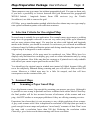
5.2 Cone Type Projections
6. Selection Criteria for the original Map
7. Scanned Maps
7.1 Scanning a Paper based Map
7.2 Optical Preparation of raw Images
7.3 Checking for twisted Map
7.4 Cutting the Map Borders
7.5 Correcting Brightness and Contrast
7.6 Sharpening the Image
7.7 Reducing the Resolution
7.8 Final sharpening the Image
8. Preparing Vector Type Maps (Macintosh only)
9. Geographic Calibration
9.1 Finding geographic Co-ordinates on Maps
9.2 Calibration of rectangular projected Maps
9.3 Calibration of Cone Type projected Maps
9.4 Calibration of UTM and Thomas Bros. Maps
9.5 There is one exception…
10. Reducing to a b/w Map Image
10.1 For PDAs with one bit per screens (MP100-130):
10.2 For PDAs with grayscale screen (MP2000):
11. Final Adjustment of Resolution and final Save
12. Cutting the map into several tiles
13. Calculation of Calibration Parameters
14. Building the Map Container Package
14.1 Importing PICT Resource Files (Macintosh)
14.2 Importing BMP Files (Windows)
14.3 How to create an empty Map (Macintosh + Windows)
14.4 Completing the map description
15. Checking the finished Map Container Package
3
3
4
4
5
5
6
8
8
8
9
9
9
10
10
10
11
12
13
13
13
15
16
17
18
18
20
20
21
22
23
24
26
28
28
33
Map Preparation Package Users Manual
Page: 3
1. Introduction
As an owner of a GPS based map navigation system it’s no long way for desiring more
and also special maps. Because of the immense diversity of world wide map material it
is not possible for a manufacturer to satisfy all such wishes. More worse, most map
material is copyrighted by the publisher and a manufacturer may distribute maps only
with great negotiation efforts and copyright costs. Therefore rarely needed maps would
be very expensive and could cost a lot of money for only covering the time for
preparing them.
By using the Map Preparation Package and this document any user with some
understanding for navigation, map projections, computer experience and the necessary
equipment will be able to produce his own Map Container Packages.
2. Legal Situation
All rights for maps belong to their publishers. Normally you may not copy or scan
maps without the written permission of the publisher. Please comply with the
copyright notice on your map.
You may scan and convert purchased paper maps to Map Container Packages
without permission of the publisher ONLY FOR YOUR OWN AND PRIVATE
USAGE!
There are applying almost the same restrictions as for copying video tapes or CDs.
If you have the written permission of the map publisher or if you own all rights by
yourself then you may market your Map Container Packages commercially.
With the purchase of the Map Preparation Package you also got the right for marketing your self-produced Map Container Packages without any licence fees to the
author as long as they are exclusively used in combination with GPS Map.
Map Preparation Package Users Manual
Page: 4
3. Hard- and Software Conditions
You will need the following equipment for creating Map Container Packages :
•
a fast Apple Macintosh or Windows computer with at least 16 MB of RAM and
a hard disk with at least 80 megabytes of free space.
•
image processing software such as Adobe Photoshop (the “LE” version will be
sufficient)
•
the development system Newton Toolkit from Apple. For creating grayscale maps
you will need version 1.6.4 for Macintosh or version 1.6.1 for Windows.
•
the Map Preparation Package
•
access to a big format scanner, if possible it should be big enough to scan your
paper map in one piece (scanning is offered by DTP studios, too)
4. Overview of the Map Preparation Process
Creating Map Container Packages consists of the following steps:
Scanned (real) maps:
•
Search for a suitable map, for both navigation purposes and for displaying on a
PDA screen
•
Scan the map (or get it in electronic form)
•
Do the optical preparation of the raw image with image processing software
(Photoshop) and reduce the result to a b/w or grayscale PICT resource file (Mac)
or BMP file (Windows)
Synthetic vector maps (currently only possible with Macintosh):
•
Draw your map by using a vector oriented drawing application such as Claris
MacDraw (Pro) or similar
Common for both:
•
For very large maps it may be neccessary to split the map into several tiles for
faster scrolling because of the limited PDA performance
Map Preparation Package Users Manual
Page: 5
•
Find map locations (calibration points) for generating the geographic reference.
You will need 3 locations for maps with a rectangular type projection or 9
locations for maps with cone type projection
•
Calculate the map description parameters by entering the selected locations into
one of the applications called RectMap-1, RectMap-2, QuadrantMap oder
ConeMap
•
Copy the resulting map description parameters into a Newton Toolkit project
template, compile it and load it into your PDA
•
Check the Map Container Package by entering the locations used for calibration
into the "Go to Position" window of GPS Map
5. Map Projection Methods
It is not necessary to be a cartographer for making Map Container Packages, but you
will need a little base knowledge.
Putting a map onto a screen is not as simple as showing a photography. Along with the
map image GPS Map will need supplementary information for finding just that image
pixel corresponding to a given geographic position.
A globe surface such as the earth may be projected to a flat surface only with some
difficulties because of its curvature. For solving this problem cartography has
developed several projection methods, each with specific advantages and
disadvantages.
5.1
Rectangular Type Projections
This projection method is especially used for topographic maps with scales ranging
from 1:1 to approx. 1:100000. Examples are city maps, walking maps or airfield maps
for aviation.
If you have a map where both latitude and longitude lines are straight, all latitude lines
as all longitude lines are running in parallel and all latitude lines are crossing the longitude lines with a 90° angle it is a rectangular type projection.
There is a projection error because of the decreasing distance between longitude lines
in pole direction, but this error can be neglected with small map scales and therefore
small regions.
Map Preparation Package Users Manual
Page: 6
The advantage of this method is the simple handling. You may determine distances
and angles simply by using a ruler and setsquare. GPS Map also takes advantage of
this method, because the geographic transformation to pixel co-ordinates is very
simple and therefore fast.
GPS Map uses a transformation method that describes a rectangular type projection
map by three special calibration points and which is able to eliminate little twist or
warp of the scanned map image.
5.2
Cone Type Projections
This projection method has many variations. It is used for maps with high scale up to
world wide maps.
f you have a map where latitude or both latitude and longitude lines are curved it is
handled as a cone type projection.
It is much more difficult to extract positions out of such maps because you must
remember the actual curving of the latitude and longitude lines at each map point.
Many road maps are cone projections, but instead of having a latitude/longitude grid
they are divided into arbitrary quadrants by a rectangular grid.
Map Preparation Package Users Manual
Page: 7
A widely available road map in US comes from Thomas Bros. and an alteration is
available through Trimble, called the Trimble Atlas.
Map Preparation Package Users Manual
Page: 8
Those maps are cone type maps, but without geographical grid. You can use them only
if you have a possibility to convert between their grid format and the geographical
WGS84 latitude / longitude format. Some GPS receivers (e.g. the Trimble
ScoutMaster) are able to convert the grid.
GPS Map uses a transformation method which describes almost any cone type map by
nine special calibration points with sufficient exactness.
6. Selection Criteria for the original Map
Not each map is suitable for our application. For example many street maps or walking
maps have no geographic reference or are not very exact (may differ up to kilometers
and are more pictures than maps). If a map has no rulers with latitude and longitude
marks at the borders you should be cautious. In such cases you will need an additional
referenced map for finding calibration points and during transferring that points to the
original map it is dangerous to make mistakes.
The optical appearance of the map must be considered, too. Most PDAs have b/w
displays only and therefore can display grey scale or colour information only by using
diverse bit patterns. Also if the map has low contrast or if printed text is only readable
with efforts you cannot expect good results on the PDA.
You should get the original map in winded state instead of folded, because folds will
never be completely flattened during scanning and you will still see folds on the PDA
screen. Moreover a folded map may be a little bit warped, and that will have
consequences on the exactness later, too.
7. Scanned Maps
7.1
Scanning a Paper based Map
Use a big format scanner, big enough for scanning your map as one piece. Although it
is possible to scan a map in portions and later combine them within Adobe Photoshop
the final product will be less accurate because of tolerances of the scanner and warping. Ask DTP studios or newspaper publishers if they are offering scanning services.
Experience has shown that it is not necessary to use a high resolution colour scanner.
A grey scale scanner with 8 bits in depth and a resolution of 200 dpi (dots per inch) is
good enough for most maps and produces “more handy” amounts of data. Don’t scan
the map with a resolution lower than 200 dpi. Reducing the resolution within
Photoshop gives better results than scanning with lower resolution.
Map Preparation Package Users Manual
7.2
Page: 9
Optical Preparation of raw Images
Load the scanned map image into Photoshop. Use the magnifier tool
for displaying the map at real size 1:1, or 100%. Now each screen pixel represents exactly one
pixel of the map image.
Because of the scanner resolution is 200 dpi and the screen resolution is only approx.
72 dpi the map seems to be magnified by nearly factor 3 compared to its paper size.
Ignore that for the moment.
Dependent of the used scanner type the map may be rotated for 90, 180 or 270
degrees. Ignore that for the moment, too.
7.3
Checking for twisted Map
Select “Show Rulers” within menu “Window” and look for straight horizontal and
vertical lines at the borders of the map. Normally maps are surrounded by rulers
which you may use for this action. Scroll the map horizontal and then vertical from
one end to the other and observe the point of intersection with the ruler. If the
intersection point at the ruler moves clearly (more than 20 pixels) during scrolling the
map may be twisted. In this case do the same with a line at the opposite side of the
map. If the intersection point moves in the same direction during scrolling your map is
twisted and should be corrected.
For correcting select “Rotate Arbitrary” within menu “Image” and insert an estimated
rotation angle. Mostly you will enter very small values in the range of 0.1 to 0.5
degrees. Now repeat the test.
If the map is still twisted then undo the previous rotate command and try again with a
new value. You should avoid more than one rotation with small angles because of loss
in image quality!
7.4
Cutting the Map Borders
Presumably your map image is bigger than the map area itself and contains rulers and
other textual information near the borders. Use the selection tool
and select the
desired image area. The command “Crop” within the “Edit” menu removes all
unnecessary image parts.
Map Preparation Package Users Manual
Page: 10
Now it is a good time to both bring a rotated map (by 90, 180 or 270 degrees) to the
proper direction and for saving the actual map image. Please use a different name to
protect your original file from being overwritten.
7.5
Correcting Brightness and Contrast
Dependant of the scanner and scanning software used both brightness and contrast
may differ from the original map. Try to correct it by using the “Adjust
Brightness/Contrast” command within menu “Image” in such a way that the image is
almost identical to the original on paper. Keep already in mind the later appearance on
the PDA screen. You will need some experience for this step as it has great influence
on the quality on the PDA screen.
7.6
Sharpening the Image
Especially text is currently not sharp enough. Use the “Sharpen” command within
menu “Filter” for improving it. The image will be more sharp now, but still not sharp
enough. But this is good for our next step, and we will call “Sharpen” again in a later
step.
7.7
Reducing the Resolution
You have scanned the map with high resolution (200 dpi?). The PDA screen has only a
resolution of 85 dpi, or 100 dpi for MP2000. To prevent the map being displayed three
times magnified you normally will reduce the image resolution.
There are a few exceptions where such a magnification makes sense, if very small map
details would disappear during reducing as found on very detailed town maps.
Photoshop gives you a possibility to reduce the resolution. Several neighbouring
pixels will be combined to less pixels by using complex algorithms. The result will be
much better than scanning the map with the same lower resolution, because Photoshop
considers grey and colour values into its calculation. Therefore text and small details
will remain readable as good as the lower resolution will allow.
Again you will need some experience for defining the new resolution. The rule is: as
low as possible but as high as necessary to preserve the readability of text and important details. Common values range from 72 to 150 dpi.
Chose “Image Size” within the “Image” menu for doing the reduction. The functionality behind this dialog is a bit tricky in Photoshop 3.x.
Map Preparation Package Users Manual
Page: 11
Using this dialog box is a bit tricky in Photoshop 3.x. “File Size” must be unchecked
and the units for width and height must be set to inches or centimeters.
Now enter the new resolution value. If you didn’t make a mistake the field “New Size”
will show a significant smaller file size. In this case click “Ok”, otherwise click
“Cancel” for repeating the action.
After reduction you should critically check your map image at many important
locations and decide if the resolution is either still too high or already too low for
seeing details good enough. If you decide to change the resolution again first use the
“Undo” command for getting the original resolution and then repeat the resolution
reduction process. Avoid reducing the resolution more than one time without undoing
because the image quality will drop down then.
7.8
Final sharpening the Image
If necessary you should now try again to sharpen the image. You may call the
“Sharpen” command within menu “Filters” more than once until the image sharpness
is satisfying. But if you call the filter too often the image quality will drop down. Use
the “Undo” and “Redo” commands for finding the best quality.
Map Preparation Package Users Manual
Page: 12
8. Preparing Vector Type Maps (Macintosh only)
Currently there is no simple to use method for creating PICT resource files with
Windows applications!
You can design your own special map, i. e. a nautical map containing a large area of
water with only some islands, shelf and coast lines or a desert map with some oasis.
The first step is thinking about the map scale you will need. A vector map has always a
screen resolution of 72 dots per inch, or 28,346 pixels per centimeter. If the scale
should be 1:1 you will need these number of pixels per centimeter or inch.
Next is thinking about the map region to be covered and to calculate the amount of
pixels in both latitude and longitude direction. As with bitmaps the borders of your
map must not exceed 32767 pixels.
For creating the map use your favourite vector based drawing application, such as
Claris MacDraw or similar.
Set the display unit to pixels and draw a rectangle with the previously calculated size
in pixels.
Draw the shapes of all elements with polygon lines and avoid using bezier curves.
Then fill the elements with bit patterns if desired. You may also insert text and small
bitmap regions (i. e. islands) from a scanned map image with same scale and
resolution, but those bitmap regions should not be greater than about 100 times 100
pixels because of the limited heap RAM within the PDA.
Draw your map in black and white only (for MP100-130) or with a maximum of
16 gray shades (MP2000)!
Save the drawing as a PICT resource file (if possible) or copy it to the clipboard, open
Apple’s ResEdit, create a new file and paste the drawing as PICT into the file. The
PICT resource must have a resource name. You can name it within ResEdit by using
the “Get Resource Info” command.
Map Preparation Package Users Manual
Page: 13
9. Geographic Calibration
9.1
Finding geographic Co-ordinates on Maps
Already during looking for a suitable map you took care of the availability of geographic information such as longitude and latitude arrangement at the map borders.
For doing the map calibration you will need position data as degrees in latitude/
longitude format, related to the WGS84 reference system. Dependend on the map and
on ist scale you may not only find full degrees but also as degrees, minutes and
seconds.
One second (expressed as “) represents 1/60 of a minute (expressed as ‘), which
represents 1/60 of a degree. The formula for converting degrees, minutes and seconds
into decimal degrees is:
Decimal degrees = degrees + (minutes + (seconds / 60) / 60)
North latitude and east longitude values are considered as positive, south latitude and
west longitude values are considered as negative.
If the co-ordinates are not referenced to WGS84 you must convert all values for
map scales between 1:1 and 1:100000 because otherwise there could occur an
error of more than 100 meters. Ask the supplier of your map for the correction
factors of your map.
The application ED50_to_WGS84
Europe) into WGS84.
converts the ED50 system (as widely used in
Some portable GPS receivers (i.e. Trimble ScoutMaster) have built-in conversion
tables for lots of referencing systems and may be used to do the conversion. Set the
receiver’s reference system to that of your map, enter all calibration points into the
receiver’s library, switch the reference system to WGS84 and read out the library.
9.2
Calibration of rectangular projected Maps
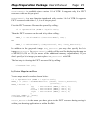
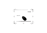
a) Traditional method for use with RectMap-1:
You will need both the geographic and pixel co-ordinates of three calibration points as
shown in the following picture.
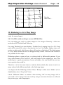
Map Preparation Package Users Manual
upper
latitude
lower
latitude
Page: 14
Cp 3
Cp 1
Cp 2
left
longitude
right
longitude
Calibration points 1 and 2 must have the same latitude value while calibration points 1
and 3 must have the same longitude value.
As bigger as the distances between point 1 and 2 and between point 1 and 3 will be, as
more exact your finished map will be, because reading errors and measurement errors
will be minimised.
Note down the geographic co-ordinates and find the related pixel co-ordinates by using
Photoshop. Chose “Show Info” within menu “Window” and activate the selection tool
to get a cross-hair cursor.
Find the three points with the cursor and note down the pixel co-ordinates as shown
within the Info window.
b) Alternative method for use with RectMap-2:
In normal case you should use method a) for calibration. However if there is no map
grid and if you are knowing only a few fixed positions on your map, or even if you
will get them directly by walking to three significant locations and writing down the
position as displayed by your GPS receiver, you can use this alternative method which
works with unrelated calibration points. Again you will need both the geographic and
pixel co-ordinates. You may choose those points freely as long as they aren't ordered
in a diagonal way. Try to find locations ordered in a similar way to method a) for best
results.
Map Preparation Package Users Manual
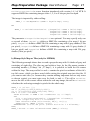
9.3
Page: 15
Calibration of Cone Type projected Maps
You will need both the geographic and pixel co-ordinates of nine calibration points as
shown in the following picture.
Calibration points 1, 2, 3 as 4, 5, 6 as 7, 8, 9 must have the same latitude value while
calibration points 1, 4, 3 as 2, 5, 8 as 3, 6, 9 must have the same longitude value.
Cp 7
Cp 8
middle
latitude
Cp 4
Cp 5
lower
latitude
Cp 1
Cp 2
left
longitude
middle
longitude
upper
lalitude
Cp 9
Cp 6
Cp 3
right
longitude
As bigger as the distances between point 1 and 3 and between point 1 and 7 will be, as
more exact will be your finished map, because reading errors and measurement errors
will be minimised.
The middle positions should be as good as possible between the outer values, but if
there is no latitude or longitude line they may be chosen a bit asymmetric as in the next
sample.
In this case you should expect some inaccuracy with positions between the left and
middle longitude and between the upper and middle longitude.
Note down the geographic co-ordinates and find the related pixel co-ordinates by using
Photoshop. Chose “Show Info” within menu “Window” and activate the selection tool
to get a cross-hair cursor.
Map Preparation Package Users Manual
Cp 7
Cp 8
Cp 4
Cp 5
Cp 6
middle
latitude
lower
latitude
Cp 1
Cp 2
Cp 3
left
longitude
middle
longitude
upper
latitude
Page: 16
Cp 9
right
longitude
Find the nine points with the cursor and note down the pixel co-ordinates as shown
within the Info window.
9.4
Calibration of UTM and Thomas Bros. Maps
These maps are also cone type projections, but they have a rectangular grid instead of a
latitude / longitude grid. Normally you will not be able to use such maps but I have
found that some GPS hand-held receivers (i.e. Trimble ScoutMaster) are able to
convert those grid co-ordinates into geographical co-ordinates if you enter the
calibration points into its library and then switch back to WGS84 display format. You
must not expect a very exact map later, but if nothing else is available it will be better
than nothing. It is very important that the grid lines are totally horizontal and vertical.
Rotate the map image for best fit.
Choose the calibration points as shown below in the centre of the quadrants. The
receiver will not be able to convert any arbitrary position, the centres of the grid
rectangles should work best.
Note down the geographic co-ordinates and find the related pixel co-ordinates by using
Photoshop. Chose “Show Info” within menu “Window” and activate the selection tool
to get a cross-hair cursor.
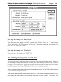
Map Preparation Package Users Manual
Cp 7
Cp 8
Cp 9
Cp 4
Cp 5
Cp 6
Cp 1
Cp 2
Cp 3
Page: 17
Find the nine points in the center of the quadrants with the cursor and note down the
pixel co-ordinates as shown within the Info window.
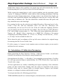
9.5
There is one exception…
The methods described above work in most cases. However, there is an exception for
all projection methods if your map covers an area with a 360 degree crack (covering
the 180° longitude) as shown below and therefore the right latitude value is less than
the left value.
The projection formulae cannot handle this crack and therefore you must use a trick
and express all longitude values as east longitude values. In the example below you
must change the right longitude value from -170° to 190° although 190° is actually out
of range. GPS Map will be aware of that and do the right things. Keep in mind to set
LongCrack to TRUE when you define the map description block later.
Cp 7
Cp 8
Cp 4
Cp 5
Cp 1
Cp 2
170°
180°
Cp 9
Cp 6
Cp 3
-170°
This does
not work
because of
the crack…
Map Preparation Package Users Manual
Cp 7
Cp 8
Cp 4
Cp 5
Cp 1
Cp 2
170°
180°
Page: 18
Cp 9
Cp 6
But this
does work…
Cp 3
190°
10. Reducing to a b/w Map Image
(only for scanned maps)
10.1 For PDAs with one bit per screens (MP100-130):
For converting grey scale or colour images to b/w images Photoshop offers two
methods called Threshold and Dithering.
For using Threshold you must define a Treshold Level ranging from 0 to 255. Each
pixel will be tested if its value is less than the level or if it is higher. Higher values will
produce a white pixel while lower values will produce a black pixel. The disadvantage
is a very hard contrast that will let disappear many details. Therefore this method is
only suitable for few maps.
Dithering replaces a group of grey or colour pixels by different bit patterns. If you
keep some distance to the screen it will look similar to the original grey tone. This
method gives a good presentation of areas and shades, but some details (as text) are
not as good as they could be.
Therefore it is the best most times to combine both methods, that means to mix two
maps reduced with different methods to the final map image.
Lets begin with the Dithering method. Chose “Bitmap” within menu “Mode” (if it is
disabled then select “Grey Scale” first).
Check “Diffusion Dither” as method. After clicking “Ok” the map image will be
converted to a b/w image. Save the result by using a new name because we will need
the previous grey scale image again.
Map Preparation Package Users Manual
Page: 19
If you are already satisfied with the result you can jump over the steps following until
we will define the map resolution.
Otherwise open the grey scale image saved last again in addition to the b/w image and
choose “Map Threshold ” within menu “Image”.
Now try changing the level until you just see that details you have missed within the
dithered map image and press “Ok”.
Select the window containing the dithered map image and put it into the clipboard by
pressing the key combination A C.
Map Preparation Package Users Manual
Page: 20
Go back to the window containing the map converted by Treshold and choose “Paste
as Layer” within menu “Edit”.
Chosen option “Darken” for mixing both images in the intended manner. The result
looks as a b/w image although it is still stored as a grey scale image. For converting it
to real b/w image choose “Bitmap” within menu “Mode”, but now set the conversion
method to Treshold with a level of 50%.
10.2 For PDAs with grayscale screen (MP2000):
You may reduce the map either to one, two or four bits per pixel, that is b/w, 4 gray
tones or 16 gray tones. Please take in mind that a map with 16 gray tones will need
four times the storage size compared to the same map in one bit per pixel resolution!
You can save some storage space by reducing the resolution of the map. This is
possible because small text is much sharper and therefore better readable on grayscale
maps compared to b/w maps.
If your map image in not already in RGB format you must convert it by selecting
“RGB-Colour” within menu “Mode”. Next select “Indicated Colours“ within menu
“Mode”. In the upcoming dialog please select either “2 bits per pixel“ corresponding
to “4 Colours“ or “4 bits per pixel“ corresponding to “16 Colours“. Also select
“Diffusion“.
Last step is changing the map to grayscale by selecting “Grayscale“ within menu
“Mode“.
11. Final Adjustment of Resolution and final Save
The Newton OS will only display images with a resolution of 72 dpi without any
scaling, so that a map pixel exactly corresponds to a screen pixel. Therefore we must
use the “Image Size” command within menu “Image” for setting the final resolution
within the image header information to 72 dpi.
This time you must check the box “File Size” to prevent Photoshop from scaling the
map image.
Map Preparation Package Users Manual
Page: 21
Saving the image on Macintosh:
You must save the image as a PICT resource file Choose “Save As…” within menu
“File” and select “PICT Resource” as file type. You must also name the resource for
later use, i.e. simply use „Map“.
Saving the image on Windows:
You must save the image as a “BMP” file.
12. Cutting the map into several tiles
Very often a map is extremely large or consists of several united map sheets. It may be
an advantage cutting that map into several parts and making seperate map container
packages out of each part. Using this method you will be able to load only the actually
needed map parts into your PDA and therefore save valuable memory.
Also a scanned map should not exceed a maximum size of 10 000 000 pixels because
of the limited PDA performance.
The partial maps should overlap some pixels (i.e. 100) at their common borders. If you
later enter the same name for all partial maps into Newton Toolkit, GPS Map will
Map Preparation Package Users Manual
Page: 22
handle those maps as they would be one single map and will automatically load the
bordering map part if you will scroll out of the actual map part..
While writing this manual there is still a special problem with the operating system
version 2.1 running on MP2000. which leads to bad scrolling performance with big
maps near to their bottom right corner. As long as there is no solution from Apple you
can only work around the problem with splitting the map into two or more tiles with
either same or different size. The tiles should have around 800 times 600 pixels and
they should be more wide than high.
For creating the tiles use the selection tool within Photoshop. Select and cut of a tile.
Create a new file with the command „New“ for each tile. Photoshop will
automatiucally size the new file to the size of the tile within the clipboard, therefore
you can simply past the tile into the new window. Save the file as a “PICT Resource
File” with a uniqe resource name, i.e. „Tile“ (Mac) mit einem einheitlichen ResourceNamen, z.B. „Kachel“ (Mac), respective as a „BMP File“ (Windows). Use names
containing an ascending number, i.e. „T0.res“ or „T0.bmp“ for the first tile, „T1.res“
or „T1.bmp“ for the second tile and so on.
Write down the pixel co-ordinates of the top left corner related to the original image
for entering into the Newton Toolkit later.
If a tile is empty, i.e. because it only contains water or dessert region, you can omit it
and therefore save memory.
13. Calculation of Calibration Parameters
Before generating the Map Container Package within Newton Toolkit we still must
calculate the parameters describing the map geographically.
Start application RectMap -1 or RectMap-2 for rectangular projected maps, ConeMap
for cone type projected maps or QuadrantMap for UTM, Thomas Bros. type maps or
Trimble Atlas maps.
All four applications are similar in handling and request inputting of the calibration
points you have noted down. Simply enter the values as requested on the screen.
Position values may be entered either as decimal degrees, degrees and decimal
minutes, or as degrees, minutes and decimal seconds.
Your input must have the following general form:
"DDD.ddd MM.mmm SS.sss" (decimal degrees, decimal minutes, decimal seconds)
Map Preparation Package Users Manual
Page: 23
By using this format you can enter all popular notations such as decimal degrees only,
degrees and decimal minutes or degrees, minutes and decimal seconds.
The different fields must be separated by spaces. West or south co-ordinates must be
entered with a leading minus sign (negative degrees).
Examples:
20° 45' 15" east, may be entered as: "20.7554167" or "20 45.25" or "20 45 15"
20° 45' 15" west, may be entered as: "-20.7554167" or "-20 45.25" or "-20 45 15"
All positions shown to the user are displayed both as decimal degrees and as degrees,
minutes and seconds.
The current application versions have no possibility for correcting mistakes. In that
case you must exit the application and restart it. An other problem will occur if your
calibration point entries are totally wrong. This could lead the complex algorithms into
an endless loop. In this case abort the application by pressing <ctrl>, <alt>, < > and
<esc>, all at the same time.
After successfully entering the values both applications offer possibilities for checking
the calibration parameters by entering either geographic co-ordinates for calculating
the corresponding pixel co-ordinates or vice versa. If you like you may test the
conversion parameters by entering your calibration points and comparing the results to
your notes.
For leaving the application enter “e(xit)” both for “Lat.” and “X”. The applications
will store the calculated parameters into the clipboard (Macintosh) or write them to a
text file (Windows) so that you can paste them directly into the Newton Toolkit.
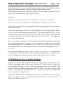
14. Building the Map Container Package
Duplicate the folder “Map Template” that is part of this package and rename the new
folder to an adequate name for your map. Drag the PCT resource files or „bmp“ files
created within Photoshop or your vector drawing application to the new folder. Start
Newton Toolkit by double-clicking the project file “Map”. Now save the project file
uinder ist own name by selecting „Save As...“ within menu „File“ to prevent NTK
from overwriting the Map Template.
If you have difficulties with opening the project file (e.g. because you are still using
NTK 1.01) simply create a new project and add all resource and layout files as
displayed within the picture to it.
Map Preparation Package Users Manual
Page: 24
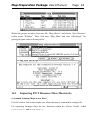
Within the project window click onto file “Map_Main.t” and choose “New Browser”
within menu “Window”. Then click onto “Map_Main” and onto “afterScript”, for
getting the same state as shown below.
14.1
Importing PICT Resource Files (Macintosh)
a) scanned (bitmap) Maps in one Piece
First let’s take a look to the simple case where the map is contained in a simgle file.
For importing immages there are two functions within the Newton Toolkit, called
GetPictAsBits and MakePixFamily.
Map Preparation Package Users Manual
Page: 25
GetPictAsBits is available since version 1.0 of NTK. It supports only b/w PICT
resources with one bit per pixel.
MakePixFamily is a new function introduced with version 1.6.4 of NTK. It supports
PICT resources with either 1, 2, 4 or 8 bits per pixel.
First the PICT resource file must be opened by calling:
rf := OpenResFileX (HOME & "myFile.res");
Then the PICT resource can be read in by either calling:
BMAP_1 := GetPictAsBits ("Resource-Name“, NIL);
or:
BMAP_1 := MakePixFamily ("BW_Resource", NIL, "Gray_Resource");
In addition to the grayscale image Gray_Resource you may also specify the b/w
image BW_Resource for MakePixFamily which will be used for displaying the map on
a MP100,110,120 or 130 (be aware of the additional memory requirements). If you
don’t specify a b/w image you mst replace "BW_Resource" with NIL.
The last step is closeing the PICT resource file by calling:
CloseResFileX (rf);
b) Vector Maps in one Piece
Vector maps must be read as shown below:
rf := OpenResFileX (HOME & " myFile.res");
BMAP_1 := {Data : GetNamedResource ("PICT", "Vector_Resource",
'picture)};
BMAP_1.bounds := {
top
: ExtractWord (BMAP_1.data, 2),
left
: ExtractWord (BMAP_1.data, 4),
bottom : ExtractWord (BMAP_1.data, 6),
right : ExtractWord (BMAP_1.data, 8)
};
SetClass (BMAP_1, 'PICT);
CloseResFileX (rf);
Vector_Resource is the name you have given to the PICT resource during saving it
within your drawing application or within ResEdit.
Map Preparation Package Users Manual
Page: 26
c) Bitmap- or Vector Style Maps as Tiles (only for MP2000)
The following example shows how to read a b/w map consisting of eight tiles. The
tiles containing PICT resources all named „Tile“ are read within a loop. As the file
names contain a ascending number („T0.res“ bis „T7.res“), it is possible to build the
file names within the loop. The arrays called dX and dY contain the pixel co-ordinates
of the tile’s top left corner, which you have noted while cutting the original map into
the tiles. If you want to omit tiles (i.e. because they contain nothing important such as
only water or dessert region) you must enter zero for both dX and dY. The call to
SetOffset moves the tiles to the correct offsets within the real map image, the call to
calcBounds calculates the enclosing rectangle in pixels for the whole map.
BMAP_1 := {Tiles: []};
dX := [0,2020,0,2020,0,2020,0,2020];
dY := [0,0,600,600,1200,1200,1800,1800];
FOR I := 0 TO 7 DO BEGIN
LOCAL Filename := HOME & "T" & NumberStr (I) & ".res";
TRY
rf := OpenResFileX (Filename);
print ("Importing File " & Filename);
Tile := GetPictAsBits ("Tile", NIL);
CALL SetOffset WITH (Tile.bounds, dX[I], dY[I]);
AddArraySlot (BMAP_1.Tiles, Tile);
CloseResFileX (rf);
ONEXCEPTION |evt.ex| DO print ("Error with File " & Filename);
END;
BMAP_1.bounds := CALL calcBounds WITH (BMAP_1.Tiles);
For reading a grayscale or vector map which is split into tiles you may simply replace
the call to GetPictAsBits by MakePixFamily or by the code around
GetNamedResource, as described already in chapter a) and b).
14.2
Importing BMP Files (Windows)
a) scanned (bitmap) Maps in one Piece
First again let’s take a look to the simple case where the map is contained in a simgle
file.
For importing immages there are two functions within the Newton Toolkit, called
GetBmpAsBits and BuildPictureViewSlot.
GetBmpAsBits is available since version 1.6 of NTK. It supports only b/w BMP files
containing images with one bit per pixel in depth.
Map Preparation Package Users Manual
Page: 27
BuildPictureViewSlot is a new function introduced with version 1.6.1 of NTK. It
supports BMP files containing images either 1, 2, 4 or 8 bits per pixel in depth.
The image is imported by either calling:
BMAP_1 := GetBmpAsBits (HOME & "myFile.bmp", NIL);
or:
BMAP_1 := BuildPictureViewSlot ({imageFile1:
imageFile2:
imageFile4:
imageFile8:
HOME
HOME
HOME
HOME
&
&
&
&
"File1.bmp",
"File2.bmp",
"File4.bmp",
"File8.bmp"});
The parameter s imageFile1 to imageFile8 are optional. You may specify only one
or several of them. imageFile1 defines a BMP file containing a b/w map (1 bit per
pixel), imageFile2 defines a BMP file file containing a map with 4 gray shades (2 bits
per pixel), imageFile4 defines a BMP file containing a map with 16 gray shades (4
bits per pixel) and imageFile8 defines a BMP file containing a map with 256 gray
shades (8 bits per pixel).
b) Bitmap Style Map as Tiles (only for MP2000)
The following example shows how to read a grayscale map with 16 shades of gray and
consisting of eight tiles. The tiles are read within a loop. As the file names contain a
ascending number („T0.bmp“ bis „T7.bmp“), it is possible to build the file names
within the loop. The arrays called dX and dY contain the pixel co-ordinates of the tile’s
top left corner, which you have noted while cutting the original map into the tiles. If
you want to omit tiles (i.e. because they contain nothing important such as only water
or dessert region) you must enter zero for both dX and dY. The call to SetOffset
moves the tiles to the correct offsets within the real map image, the call to calcBounds
calculates the enclosing rectangle in pixels for the whole map.
BMAP_1 := {Tiles: []};
dX := [0,2020,0,2020,0,2020,0,2020];
dY := [0,0,600,600,1200,1200,1800,1800];
FOR I := 0 TO 7 DO BEGIN
LOCAL Filename := HOME & "T" & NumberStr (I) & ".bmp";
TRY
Tile := BuildPictureViewSlot ({imageFile4: Filename});
print ("Importing File " & Filename);
CALL SetOffset WITH (Tile.bounds, dX[I], dY[I]);
AddArraySlot (BMAP_1.Tiles, Tile);
ONEXCEPTION |evt.ex| DO print ("Error with File " & Filename);
END;
BMAP_1.bounds := CALL calcBounds WITH (BMAP_1.Tiles);
Map Preparation Package Users Manual
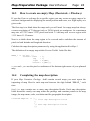
14.3
Page: 28
How to create an empty Map (Macintosh + Windows)
If you don’t have a real map for a specific region you may create an empty map to be
used as a background for displaying the actual position and route, or a flight replay at a
given scale.
The first step is to think about the map scale you will need. An empty map has always
a screen resolution of 72 dots per inch, or 28,346 pixels per centimeter. At a maximum
map size of 32767 times 32767 pixels and scale 1:1 the map will cover a region with
11.55 times 11.55 meters.
Next is to think about the map region to be covered and to calculate the amount of
pixels in both latitude and longitude direction
Calculate the map description parameters by using the application RectMap-1.
The definition of an empty map within Newton Toolkit looks like this:
BMAP_1 := {Tiles: [],
bounds: {left
top
right
bottom
:
:
:
:
0,
0,
X_MAX,
Y_MAX}};
X_MAX and Y_MAX are the pixel co-ordinates of the bottom right corner of your planned
map.
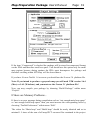
14.4
Completing the map description
If your Map Container Package shall contain several maps you must repeat the
importing of map files for each map and increase the digit behind “BMAP_” each
time.
MapList may contain one or more map description blocks. Each map description
block describes exactly one map within the package and contains pointer to the map
image, the map name, scale, resolution and the geographic description.
thisView.MapList := [{
// first map description block
},
{
// more map description blocks
}];
Map Preparation Package Users Manual
Page: 29
Next complete the first map description block.
First paste the calibration parameters that should be still in the clipboard (Mac) or
within a text file (Windows) to the position marked by a comment. Then fill in the
following fields:
Name
Name of the map as it should be shown within GPS Map, i. e. “ICAO”.
If your map is part of a bigger map area, all maps belonging to that area
must have the same name. That will enable GPS Map to handle them
as if they would be a single big map.
Comment
Each Map Container Package is stored as an independent application
on the PDA. If you will start one by tapping there will be a scrollable
list showing all contained maps by their comment string. You should
choose an expressive comment like “ICAO Stuttgart 1995”.
theBits
Reference to the image of the map. Insert the variable “BMAP_x” here,
where x is the running number of the current map.
Scale
Scale of the map, e.g. enter 500000 for a scale of 1:500000.
Resolution
Optical resolution of the map after its reduction, e.g. 130 for 130 dots
per inch. This value will be used for calculating the magnification
factor displayed within GPS Map.
ScaleFactor Temporary value used for sorting maps. Calculate it as (Scale /
Resolution) and use the integer part only
Type
‘RECT for rectangular projections (as calculated by RectMap-1 or
RectMap-2) or ‘CONE for cone type projections.(as calculated by
ConeMap or QuadrantMap)
Version
Version of the map description block, must be always 1
LongCrack
Must be TRUE for maps with longitude crack (if the map overlaps 180°
longitude) and NIL for maps without longitude crack.
Public
Must be TRUE if the GPS Map demo version should recognise this
map. Else delete this slot or set it to NIL .
C_X
C_Y
C_Long
Map Preparation Package Users Manual
C_Lat
A
Page: 30
Those slots describe the map projection. You will get them as an output
from one of the programs RectMap-1, RectMap-2, ConeMap or
QuadrantMap either via the Macintosh clipboard or a Windows text
file
Lat_top
The following four slots are only used for cone type projections with
borders not being horizontal or vertical. You may enter a top latitude
limit. If the current latitude exceeds this limit GPS Map will
automatically look for a joining map. If the value is NIL then GPS Map
will look for a joining map just after leaving the current map pixel area.
Lat_bottom
Same as before, but for a bottom limit.
Long_left
Same as before, but for a left limit.
Long_right
Same as before, but for a right limit. Remember to add 360 degrees to
the value if LongCrack is TRUE!
Def_Lat
Def_Long
Geographic default co-ordinate for loading the map if there is no GPS
position available (i.e. use the co-ordinate of the map centre point).
Even if your map has a longitude crack you must use the real coordinates (-180°..180°).
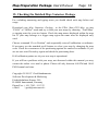
After you have entered all data and cleared all unused description blocks click into
field at the lower left edge of the window for translating the afterScript slot.
Next choose command “Settings” within menu “Project” for setting the name for the
Map Container Package (starting with NTK 1.5 this window looks different).
Type the name for your package into field “Application/Name”. The name should be
shorter than 10 characters. Use the same name for fields “Application/Symbol” and
“Package/Name” but extend it by the string “:GESTAUD”. This extension is used by
GPS Map for recognising the package as a Map Container Package .
If the item “Copy protected” is checked the package will not be saved during
synchronisation with the Newton Connection Kit. That is recommended if the package
is bigger than 1 megabyte because else synchronising will take a very long time. If you
have lost such a package you can reinstall it as often as needed and therefore a backup
is not important.
Map Preparation Package Users Manual
Page: 31
If the item “Compressed” is checked the package will be stored in compressed format
on the PDA and therefore need less space. You should use this option only for small
map regions because during runtime the PDA must decompress the package and
therefore scrolling within GPS Map will be slowed down.
If you have Newton Toolkit 1.6 or newer you should use the Newton 2.0 platform file.
Note: If you intend to produce a grayscale map you will need NTK version 1.6.4
(Mac) or 1.6.1 (Windows), and you must use the Newton 2.1 platform file!
Now you may compile your package by choosing “Build Package” within menu
“Project”.
If there are Memory Problems...
If there is an error message during compilation such as “not enough main heap space”
or “not enough build heap space” then you must increase the corresponding value by
choosing “Toolkit Preferences” within menu “Edit”.
The values for “Main heap” and “Build heap” should be nearly identical and set to
minimal 1.5 times of the sum of all map PICT resource files contained in the project.
Map Preparation Package Users Manual
Page: 32
Because PICT files are compressed you should get the real size from within
Photoshop. A good value is 8 megabytes for each heap.
After closing the window you must exit and restart Newton Toolkit to let the changes
take effect.
Macintosh specific:
If now there is an error message as “Could not launch Newton Toolkit because there is
not enough memory” then you must also increase the memory partition as defined
within the Finder. Select the Newton Toolkit
application and then choose
“Information” within Finder menu “File”.
Change the partition value at least to the sum of “Main heap” and “Build heap”. If this
is more than you have physical memory installed you must increase your memory by
starting virtual memory management. See your computer’s documentation for details
Map Preparation Package Users Manual
Page: 33
15. Checking the finished Map Container Package
For excluding measuring and typing errors you should check each map before real
usage.
Download your Map Container Package to the PDA. Start GPS Map, go into
“PLAN” or “Offline” mode and try to load your new maps by choosing “Load Map”
or tapping onto the overview button. Check the map names displayed within the map
list. If your map belongs to a bigger map region the name must be displayed only
once!
Choose command “Go to Position” and sequentially enter all calibration co-ordinates.
If necessary use the standard scroll buttons to select your map by changing the map
scale. Check the correctness of the positioning against the entered co-ordinates. If you
are not sure start Photoshop again and check the positioning there.
If all calibration points are ok your new map is operational.
If you still have problems with your map, not discussed within this manual you may
contact the author via e-mail or phone. Please call only between 6:00 PM and 10:00
PM German local time.
Copyright ©1995-97 Gerd Staudenmaier
Software Development & Marketing
Friedrichshafener Strasse 24 b
D-88090 Immenstaad, Germany
Phone/Fax: (..49) 7545 - 911 322
e-Mail:
<[email protected]>