1
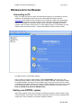
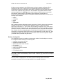
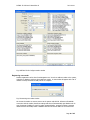
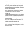
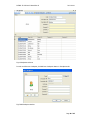
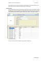
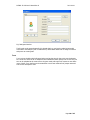
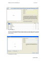
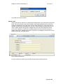
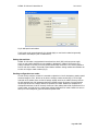
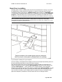
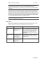
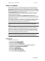
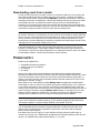
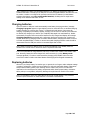
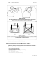
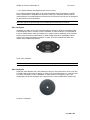
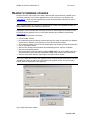
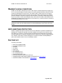
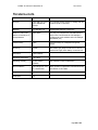
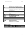
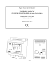
Handheld Guard Tracking System PATROL II LCD Firmware version: fv 2.06.0093 Document version: Rev. D PATROL II LCD User's Manual Rev.D 2011-04-01 CONSTRUCTION AND USAGE PATROL II LCD is a portable proximity ID reader designed for tracking of the guards’ work. The principle of device work is to collect dates and times when guard registered his attendance at specific facility points where proximity checkpoints were located. As a checkpoint any EM 125 KHz proximity transponder can be used (e.g. card, tag, key fob, disc) or a special checkpoints dedicated for PATROL II guard tracking system (e.g. PK-2 or PK-3 offered by Roger). The PATROL II LCD stores in internal memory checkpoint codes together with dates and times they were read. It can record up to 32.768 logs in total. The reader can be supplied from the disposable (one time use) or rechargeable LR6 (AA) type batteries. Rechargeable batteries can be charged directly from the PC USB port to which reader is connected or using dedicated AC charger provided with the device. The USB port is also used for configuration and events downloading from the reader. PATROL II LCD requires Patrol Master v.3 software (Win 98/NT/2K/XP/Vista/W7). Page 2 of 25 PATROL II LCD User's Manual Rev.D 2011-04-01 FEATURES Operates with EM 125 KHz proximity cards and tags LCD display with backlight Non-violate 32.768 event log buffer Non- erasable event register Guard tour, alarms and maintenance events Displays guard and checkpoint names Displays guard tour schedule hints Battery charging from PC’s USB or AC charger Powered from two LR6 (AA) batteries Resistant to humidity and water condensation One button intuitive operation Up to 8K reads cycles without battery charging (*) Shock resistant for 1.5m free falling (*) Programming and maintenance through USB Firmware upgrade via USB Free managing software for Windows Operating temperature -35°..+60°C CE approval (*) - Detailed specification of these features is explained later in this document Page 3 of 25 PATROL II LCD User's Manual Rev.D 2011-04-01 WORKING WITH THE READER Connecting to PC Before you begin work with the reader, the Patrol Master software (v3) and USB driver must be installed on the designated computer (they can be downloaded from Roger’s web site: www.roger.pl) then reader can be connected to any free USB port. Reader will be automatically registered in the computer as another serial port. Once connected to USB reader automatically switches from standby to normal work and will remain in this state until plugged off from the computer. With the reader connected to PC run Patrol Master program. In Patrol Master go to the Readers tab and click Connect button - software will establish connection with the reader. Fig.1 Main window of Patrol Master software After connecting to computer reader displays message Online Mode and remains in it until finishing work with software. Active connection with a reader is indicated in Patrol Master software by message ONLINE in the Status field of the Readers tag. Lack of active connection with a reader is indicated in Patrol Master software with message OFFLINE . Establishing connection with a reader as well as disconnecting it from computer is written in the event memory of the device (events: Enter to ONLINE mode, Exit from ONLINE mode). Starting new PATROL system Patrol Master software can be used to manage many different guard tour systems (objects) using numerous PATROL II LCD readers. This function is particularly useful for security companies which usually work in many companies or institutions in different locations. . Page 4 of 25 PATROL II LCD User's Manual Rev.D 2011-04-01 All data concerning settings of each PATROL system are kept in separate configuration file of extension RGT and of free to choose name (for example Bank KLM.rgt, Shop ABC.rgt etc.). Configuration file contain all information about readers, checkpoints, tours and guards, but do not contain events registered during guard tours. After installation Patrol Master software contains example configuration file Demo.rgt, where typical settings of PATROL system are presented. Demonstration system consist of: two readers, several checkpoints, guards and tours. In order to create new PATROL system, use File/New command, and then define, one by one, the following system elements: readers checkpoints guards tours special cards After completing settings configuration process, save them to file with a chosen name (command: File/Save as ). From now on, each time before plugging a reader, it is required to load an appropriate configuration file – the one which was used during configuration of the reader. Patrol Master software automatically loads last used configuration file, it is however possible to choose it manually if necessary. If software will be launched without the right configuration file data loaded from a reader will not be interpreted properly. This will cause for example, that no (or improper) checkpoints or guards names will be shown next to events registered by a reader. Each time, after introducing any changes to system settings, it is essential to save them in configuration file RGT (command: Save as ) otherwise they will be lost. Reader’s Configuration The configuration process is as simple as connecting the reader to PC and sending to its memory the configuration data consisting of the following items: checkpoint names and its ID codes guards names and its ID codes special cards names and its ID codes tour schedule current date and time reader’s name and its ID number type of batteries LCD backlight intensity Note: Both, checkpoints and guard ID cards can be read using the PATROL II LCD being connected to the USB or can be entered manually if theirs ID codes are known (e.g. printed on the checkpoint or card surface). Once the reader is configured it can be used for guard tour tracking however it should be periodically connected to PC for event log download or for changing of the setup. Page 5 of 25 PATROL II LCD User's Manual Rev.D 2011-04-01 Fig.2 PATROL II LCD Configure reader window Registering new reader Readers registration can be done from Navigation tree. In order to add new reader to the system, right click on Readers , and then choose Add new reader . A new window will appear with a list of readers currently connected to USB ports of PC computer Fig.3 Connecting new reader window We choose the reader we want to connect to the system and click OK. Software will establish connection with the reader, identify its settings and then will automatically open Readers tab. In case of attempt of adding to system a reader registered before, program will show a message Reader with this ID already exists in database and will not allow to add it for the second time. Page 6 of 25 PATROL II LCD User's Manual Rev.D 2011-04-01 To configure new connected reader, click Configure button in Readers tab. Configure reader window will appear (Fig.2). In this window define all available parameters: name of the reader, LCD backlight intensity, type of batteries, date & time. In order to fully prepare the device to service, define additionally checkpoints, guards and also assign one of available tours. Assigning these parameters to reader is possible only if they have been previously defined in the system. If there are no checkpoints or guards it is necessary to define them in first step, and then getting back to readers configuration. Sending settings to reader can be done using Upload configuration to reader button. After installation software does not contain any readers. Changing reader’s settings can be done in the same way as new one’s configuration. Only fields in Configure reader window can be modified. Readers tab does not allow to change any settings. Battery and LCD configuration Factory new reader is delivered with two 2100 mAh rechargeable batteries which are its default setup. Eventually, it can be configured for 1000 mAh NiMh or ordinary disposal (single use) ones. Prior to replacement of batteries reader must be configured for the new ones. Note: If you place non-rechargeable batteries and connect reader to USB port or AC charger this will cause battery damage. The LCD display has backlight which intensity can be adjusted from 0 to 100%. The LCD backlight consumes significant amount of energy which have strong influence on number of read cycles without necessity to recharge batteries. If LCD backlight is configured to 0% reader can provide up to 8.000 read cycles while when set to 100% it is reduced to 3.000 cycles only. In most cases the 25% LCD backlight level is enough for good visibility in a dark. Note: The number of read cycles presented above are average values achieved on new, fully charged 2100 mAh NiMh batteries. Battery type as well as LCD backlight setting can be done in Configure reader window (Fig.2). Note : In order to save changes in configuration it is essential to send them to reader using command Upload configuration to reader in reader configuration window.. Checkpoints configuration Each checkpoint must have individual ID number (code) and optionally name, comment and picture. The name of the checkpoint is displayed on LCD and is presented in the event screen of the Patrol Master software. If no name has been defined or checkpoint is unknown reader will display and register its ID code only. Page 7 of 25 PATROL II LCD User's Manual Rev.D 2011-04-01 Fig.4 Checkpoints tab view In order to define new checkpoint, click Add new checkpoint button in Checkpoints tab. Fig.5 Add checkpoint window Page 8 of 25 PATROL II LCD User's Manual Rev.D 2011-04-01 The checkpoint code can be entered manually (12 decimal digits) or read via the PATROL II LCD reader being actually connected to the USB port (click on Read button). Guard ID cards Each guard may have its ID card. Programming of the ID cards for guard is not obligatory however when defined in the system they allow to monitor guards’ activity during his duty hours. Each time a guard starts his duty, he should log in the reader using his ID card. From now on all events which took place during the duty will be assigned to it after events analyze in Patrol Master software. Fig.6 Guards tab view In order to define new guard, click Add new guard button in Guards tab. Page 9 of 25 PATROL II LCD User's Manual Rev.D 2011-04-01 Fig.7 Add guard window The ID code can be entered manually (12 decimal digits) or read via the reader being actually connected to the USB port (click on Read button). Patrol Master allows also to assign a comment and picture to certain guard. Tours Tour is a time schedule which tells guard where and at what time he has to visit next checkpoint. As a result tour consist of list of checkpoints and related times which specify time of visit. Only one tour can be uploaded at the same time to the given reader, although in the system we can define many of them. Tours defining can be omitted but in such case reader will not prompt name and time of next checkpoint to visit. Page 10 of 25 PATROL II LCD User's Manual Rev.D 2011-04-01 Fig.8 Tours tab view Each tour can have assigned additional comment and picture. In order to define new tour, click Add new tour button in Guards tab. In order to define new visit point within existing tour, click Add new visit point button. Fig.9 Add new tour window Page 11 of 25 PATROL II LCD User's Manual Rev.D 2011-04-01 Fig.10 Add new visit point window Special cards Special cards have the same form of 125kHz passive transponders just as checkpoints and guard ID cards. They can be defined in the system to register some special predefined events (other than registering checkpoints or duty shift) which can occur during guard’s duty. These event can be for example: opened window, light switched on, intrusion, vehicle entering the protected area etc. In order to register special events, guard is equipped with set of cards, each assigned to another event. Event registration is simply done by reading special card in the same way checkpoint or guard ID card is read. Defining special cards in the system is not obligatory, however their use can broaden functionality of PATROL system. Fig.11 Special cards tab view In order to define new special card, click Add new special card in Special cards tab. Page 12 of 25 PATROL II LCD User's Manual Rev.D 2011-04-01 Fig.12 Add special card window The ID code can be entered manually (12 decimal digits) or read via the reader being actually connected to the USB port (click on Read button). Setting date and time PATROL II LCD reader is equipped with internal real time clock (RTC) with own power supply source in case reader’s batteries are not available or discharged. Reader’s RTC accuracy is in practice sufficient to let using it for many months without any correction. It is of course possible to set RTC each time reader is connected to Patrol Master software. Setting readers time and date can be done in Configure reader window (Fig.2). Sending configuration to a reader In order to fully configure a reader it is essential to upload to it a list of checkpoints, guards, special cards and assign it a tour. All this can be done in Configure reader window (Fig.2). On the right hand side of the window there are lists of settings actually stored in the reader’s memory while on the left hand side lists of all parameters defined in PATROL system. By means of arrows between left and right list we can configure data to be upload to the reader. Window tour displays list of checkpoints and times of visit of currently chosen tour. After making desired list of parameters for a certain reader, we send them to it using button Upload configuration to reader . Reader can store in total up to 1000 checkpoints, guard ID cards and special cards. Page 13 of 25 PATROL II LCD User's Manual Rev.D 2011-04-01 Guard tour recording Normally, reader remains in standby mode and consumes minimal amount of energy. If you press the ON/OFF button reader switches from standby to normal work showing welcome message containing the device’s type name (e.g. PATROL II LCD) and its version (e.g. v2.06.0093). After 2 seconds reader automatically starts reading of the checkpoint’s/card code (message Reading in progress ..) which lasts about 5 sec. During this period you should put the reader close to the checkpoint (or guard ID card/special card) and its ID code will be read and saved to the event log. Note: It should be noted that the maximum reading distance is different for various tags nevertheless the optimal reading distance is achieved when the reader’s axis is approx. 45° to the checkpoint’s/card plane as presented below. Fig.13 Example of reading PK-3 type checkpoint Once the reading is accomplished device displays a name of the checkpoint’s/card being read or its ID code in decimal format (DEC) in case the ID code is unknown. After that step reader shows the next checkpoint to be visited according to programmed tour together with planned visit time (message: Next checkpoint) and then free event memory size (message: Event log free: … ) with a number of free memory locations. In the end reader displays current date and time then finally switches to standby mode (Going to standby). In order to read checkpoint’s/card code again you should repeat above steps anew. Eventually, you don’t have to wait for the reader to go to standby mode but instead of this press the ON/OFF button again when date/time is presented on LCD and reader will return to reading procedure. Page 14 of 25 PATROL II LCD User's Manual Rev.D 2011-04-01 Note: When the reader is connected to USB port it skip switching to standby but continuously remains in a date/time display mode. In such a case pressing ON/OFF button causes checkpoint/card reading process to be repeated. Also, when connected to USB it skips displaying tour schedule. The process of reader’s usage should be started from reading an guard ID card belonging to the guard who starts the shift. During routes guard logs his attendance in the specific facility locations by reading checkpoint’s ID codes. After guard’s shift is finished he hands the reader over to his replacement. In first step the replacement registers his guard ID card in the reader and then starts his shift. All events occurring from the moment when given guard registered his guard ID card to the moment when next guard register itself are interpreted as assigned to his individual account — i.e. the Patrol Master displays info that they occurred during his shift. Note: Reader can log events without a necessity to read a guard’s ID card however in such case events will not be assigned to any guard person. ON/OFF Button PATROL II LCD is equipped with one button which function depends on actual phase of reader’s logic. Below explanation of action caused by ON/OFF button in various situations: Situation Action Notes Reader in standby mode Pressing ON/OFF button switches device to normal working mode Once in normal working mode reader displays welcome info with device’s type and version and after that goes through entire checkpoint/card reading procedure. If ON/OFF button is not pressed again device switches automatically to standby mode Reader in charging mode Pressing ON/OFF button stops charging process and reader switches to time/date display mode Pressing ON/OFF button again when reader in time/date display mode initiates checkpoint/card reading procedure Reader displaying current time/date Pressing ON/OFF button initiates checkpoint/card reading process Page 15 of 25 PATROL II LCD User's Manual Rev.D 2011-04-01 EVENT LOG MEMORY Reader is capable to record up to 32.768 events together with their time stamp (date and time). Each time the checkpoint/guard ID card is read, reader displays its name and then information about remaining free memory. When memory is occupied in 90% reader displays warning Event log almost full accompanied with 2400/1800 Hz modulated alarm signal. To confirm this message guard have to press ON/OFF button and then reader will continue its normal work, if not reader will switch off and the appears again with the next working cycle. The Event log almost full warning is a prompt for the user to transfer memory content to the computer otherwise it may happen that in the nearest future event buffer will be completely occupied and some events will be lost. In case when buffer is full reader displays warning Event log full accompanied with the 2400/1800 Hz alert sound. To confirm this message guard have to press ON/OFF button and then reader will continue its normal work, if not reader will switch off and the message will be displayed again with next working cycle. Both warnings are registered in the reader’s log. Once confirmed through ON/OFF button they are no more registered in reader’s memory however they are recalled with every reading cycle but this time they disappear automatically after 1s and no sound is generated at all. This repeated messages are intended to remind the guard about existing problems. Note: When event buffer is overload the new coming events are saved on locations already occupied by the oldest ones thus some events are lost and event history is discontinued in some degree. Events can be downloaded to PC database using command: Download events in Readers tab. Events which are read are not automatically deleted from reader’s memory, they still exist in the reader and can be read again. If you don’t want to keep these events in device use command: Delete events from reader . This command protects the program from reading the same events again however it doesn’t delete them physically from the memory – thanks to this it is possible to read them again using special command: Recover deleted events . Note: Before you will read event buffer from the given reader assure the Patrol Master has already opened proper configuration file (the same RGT file which was used for configuration of a given reader) otherwise events might be displayed with wrong names of guards and checkpoints. Event types Reader records following events: Start of battery charging (Start of charging) End of battery charging (End of charging) Battery charging stopped (Charging stopped) Warning about low battery level (Battery week) Warning about memory being occupied in more than 90%(Event log almost full) Warning about memory being fully occupied (Event log full) Configuration changed (New configuration uploaded) Date/time change (Date/time set) Event log erasure (Event log erased) Online mode on (Entry to the online mode) Online mode off (Exit from the online mode) Error in configuration settings (Configuration error) Page 16 of 25 PATROL II LCD User's Manual Rev.D 2011-04-01 Downloading event from a reader In order to read event log from a reader, it has to be connected to USB port of PC computer with Patrol Master software launched. In Readers tab click Connect button – computer will establish connection with the reader, showing message ONLINE in Status field. When reader is online click Download events button in Readers tab – software will download and show all events from reader. Downloaded events are not erased from reader’s memory and can be downloaded again if necessary. If it is required, events can be set as archival (button Delete events from reader ) and will be omitted while downloading event log for the next time. Nevertheless archival events can be restored and set again as actual by means of button Recover deleted events . Note : There is no software method to erase events from reader’s memory. Old events are kept in the memory until they are overwritten by new ones, when 32 000 event limit is reached. After that there is no way to restore old events as they physically do not exist in the memory anymore (their memory cells have been replaced by new events). Because of relatively large buffer size (32k), causing memory overflow deliberately is practically very difficult and requires large amount of time (about 88 hours of continuously reading cycles) to do it. Events downloaded from a reader can be browsed and analyzed on computer’s screen as well printed on connected printer. Patrol Master software enables writing event log to special file of .xml extension. These files are totally independent from configuration files RGT, and can be loaded to Patrol Master software or browed and processed in another software. POWER SUPPLY Reader can be supplied from: rechargeable LR6 (AA size) batteries ordinary (one time use) batteries PC’s USB port AC charger Factory new reader is delivered with NiMh/2100 mAh batteries fully charged and formatted. Normally, this batteries can provide up to 8000 read cycles with LED backlight switched off or 3000 with 100% LED backlit. These numbers are continuously reduced with batteries getting older. In general, it should be assumed, that rechargeable batteries should be replaced once a year or two (depending on intensity of usage). When battery is low, reader displays message Battery weak accompanied by 2400Hz/1800Hz alarm signal. In order to continue work, guard should press the ON/OFF button. If not, reader will not go further and switch off. Once warning is confirmed by pressing ON/OFF button reader will continue work however with every read cycle it will remind the user about week battery but will not require message confirmation. Displaying Battery weak message is a warning for the user that batteries should be charged or replaced soon. For battery charging use the dedicated charger delivered with the PATROL II LCD set or charge them directly from the PC USB port. Note: It may happen that PC USB port is not able to provide amount of power to charge batteries (up to 0.5 A are required for battery charging). In such situation charging should be performed from another computer or using AC charger attached to the PATROL II LCD set. It is recommended that only original AC charger provided with a reader should be used. Using different types of chargers does not guarantee a proper work of the device and can damage device’s circuits and/or batteries. Even without any source of supply (e.g. when batteries are being removed) reader keeps its internal clock running. This is maintained by an additional (internal) backup battery which does not require to be replaced during reader’s planed lifetime (i.e. 10 years). Page 17 of 25 PATROL II LCD User's Manual Rev.D 2011-04-01 Note: Supplying the reader from disposable batteries (e.g. alkaline) is allowed only under the condition that before connecting to the USB port the non-rechargeable batteries are taken out from the reader or reader is reconfigured for operation with this kind of batteries (in Patrol Master software select battery type: Non-rechargeable batteries). Violating this rule might cause damage to the batteries and reader as well. Charging batteries Upon connection to USB port reader automatically starts battery charging procedure (message Charging in progress appears in upper display line and on the bottom line an animated charging symbol consisting of a growing line of stars (*) followed with total amount of time spent for charging). Depending on the battery capacity, charging can last from few minutes (if the batteries are almost fully charged) up to 8 hours (for completely discharged 2100 mAh batteries). Reader automatically recognizes the moment when batteries are fully charged and displays the message Charging completed accompanied with a information about total charging time. Pressing the ON/OFF button during charging makes the reader abandon battery charging and switch to normal work with time/date display. In order to resume interrupted charging procedure reader should be disconnected from the USB port and the re-connected again after a while. Note: Reader connected to USB port does not switch automatically to the standby mode but remains in the normal work for entire time when it is powered from USB. It is not recommended to charge batteries with every occasion when reader is connected to USB port. Generally, battery should be charged only when necessary (e.g. when Battery weak message appeared). In order to avoid unnecessary charging press ON/OFF button first then connect the reader to USB or start Patrol Master and charging will be stopped automatically. Replacing batteries Whenever you change battery for another type or capacity do not forget to make adequate settings in reader’s configuration. Follow instructions bellow for easy and comfortable battery replacement. Always observe battery polarity when inserting into the reader. Note, there is an instruction imprinted on the internal space of battery compartment which shows proper battery orientation. When polarity is wrong battery will quickly discharge through electronic module of the reader. Note: It is forbidden to throw out waste batteries along with normal garbage. They should be stored in special containers for waste batteries or sent back to manufacturer. Page 18 of 25 PATROL II LCD User's Manual Rev.D 2011-04-01 Fig.14 How to replace batteries in PATROL II LCD reader CHECKPOINTS AND GUARD ID CARDS TYPES Reader allows reading of any proximity transponder of EM 125 KHz standard. Transponders (proximity tags) of this type are very popular and available in various forms. The most common are: thin ISO card (Roger item: EMC-1) thick ISO card (Roger item: EMC-2) key fob (various shapes and sizes, Roger item: EMKF-1) discs (various sizes) foils (various shapes and sizes) PK-3 (check point in a plastic, hermetic case) Page 19 of 25 PATROL II LCD User's Manual Rev.D 2011-04-01 PK-2 (50mm diameter disc-shaped tag with a hole in center) Any of the transponders listed above can be used with PATROL reader as checkpoint, guard ID cards or special cards. Transponders are different in shape, size, mechanical resilience and the reading distance. For guards identifiers the best choice are ISO card or key fobs, but as checkpoints the PK-3 and PK-2 are recommended. Note: None type of the proximity tags can be installed behind metal sheet or structure. PK-3 checkpoint Checkpoint in a plastic case of high mechanical resilience. Allows for sticking a self-adhesive label with checkpoint’s name or number. In case of installation on metal surfaces it is recommended to put a non-metallic spacer under the checkpoint (e.g. perspex, plaster cardboard), which should be at least 10mm thick. When installed direct on metal reading range will be significantly reduced however still it will be acceptable for PATROL II reader. PK-3 can be located both indoor and outdoor without additional protections. Fig.15 PK-3 checkpoint Note : Mounting PK-3 on metal surface reduces its reading range of about 30-50% . PK-2 checkpoint Plastic disc 50mm diameter with a hole allowing for fixing it to the surface with a screw. It can also be hidden inside a wall (under the plaster) or under a thin non-metallic barrier (e.g. under the glass or a plaster cardboard). In case of installation on metal surfaces it is obligatory to put a nonmetallic spacer under the checkpoint min. 10mm thick. PK-2 can be installed indoor location only. Fig.16 PK-2 checkpoint Page 20 of 25 PATROL II LCD User's Manual Rev.D 2011-04-01 READER’S FIRMWARE UPGRADE Despite of the fact, that a factory new reader is delivered with a latest firmware available in the moment of production it can be later upgraded to the newer versions (for new firmware visit www.roger.pl ). Please note that upgrades may contain both functionality extensions as well as corrections to the errors recognized. Note: It should be taken as a rule that for management of a reader with upgraded firmware, the latest available software Patrol Master should be used. Upgrading a reader’s firmware does not require access to its internal space of the reader and can be performed using RogerISP v4.0.10.27 and higher software (also available for download at www.roger.pl ). Firmware upgrade procedure is as follows: Connect reader to the PC Run RogerISP program and specify communication port the reader is registered in the Windows system (there is 'PATROL II LCD' phrase next to the listed COM port number) In the Firmware window select a new file containing the new firmware (file with HEX extension) Click on the Program button Wait until the message with information that downloading process has been completed Exit from the RogerISP program After programming reader may display message Config. error if so press ON/OFF button this will clear this alarm and reader will automatically initialize setup memory with default values Start the Patrol Master software and configure the reader from the scratch Note: If the reader does not start after upgrade process, it may mean that wrong HEX file has been uploaded to the device or that errors occurred during the upgrade process. In such case entire process should be repeated from the beginning. Fig.17 Roger ISP software window Page 21 of 25 PATROL II LCD User's Manual Rev.D 2011-04-01 READER’S USING CONDITIONS PATROL II LCD reader is designed to work in a wide range of external temperatures ranging from 25° to +60°C and humidity up to 95% however it must be protected from direct influence of fluids (cannot be submerged or left on the rain). If a reader is used in a lather case it can be used for short time during intensive showers however the time when reader is exposed to such conditions should be reduced to a minimum required to read checkpoint or card. After reading device should be put to a pocket or another protected place. Also, when used in the leather case, PATROL II LCD withstands free falling from the 1.5m height to a hard surface (e.g. concrete) however it should not be intentionally exposed to such event. Note: PATROL II LCD should be used in a lather case which on one hand safeguards it against getting wet, and on the other hand protects from mechanical damage in case it falls onto a hard surface. ANTI-SABOTAGE PROTECTION Reader is equipped with special components and circuits dedicated for protection and detection of sabotage acts, in particular exposing to microwave radiation (microwave oven) as well as using high voltage (e.g. 230V AC). In case the Roger’s technical personnel detects that such situations occurred, reader loses its warranty coverage and can be repaired out of warranty, against payment only. However some kinds of extensive damages to the electronic module exclude possibility to repair, about what the device’s owner is individually notified. FACTORY KIT The factory kit includes: Patrol II LCD handheld reader two batteries NiMh/2100 mAh USB cable AC charger leather case user’s manual PK-3 checkpoint (1 pc) PK-2 checkpoints (5 pc) proximity ISO card thin (3 pc) horizontal card punch (etui) for ISO card (3 pc) managing program Patrol Master available for download from www.roger.pl USB drivers available for download from www.roger.pl Page 22 of 25 PATROL II LCD User's Manual Rev.D 2011-04-01 TECHNICAL DATA Parameter Value Notes Charging From USB port of PC or from dedicated AC charger The charging process requires 5V voltage and may consume up to 0.5 A current Batteries 2 x LR6 (AA) 1.5V Rechargeable batteries or single use Number of read cycles without a necessity to recharge batteries 3000…8000 For new, fully charged 2100 mAh NiMh batteries where 3000 is achieved when LCD backlight is configured to 100% and 8000 with LCD backlight deactivated (0%) Labels memory 1000 Internal memory for checkpoints and guards names Events log 32.768 Non-violate type, keeps records even in case of total lack of supply either battery or external one Dimensions 79x117x24mm Operating temperature -25..+60°C Operating humidity 0..95% relative humidity Also resistant to water condensation Shock resistance Free falling from 1.5m to a hard surface When located in original lather case delivered with the PATROL II LCD reader Weight ≈200g Certificates CE Page 23 of 25 PATROL II LCD User's Manual Rev.D 2011-04-01 ORDERING INFORMATION Item Description PATROL II LCD PATROL II LCD reader with set to auxiliary equipment as listed in product documentation (see section: Factory Kit earlier in this document) PK-3 Outdoor proximity checkpoint in a plastic enclosure, operating temperature range -40°..+80°C, can be installed on a metal surface PK-2 Indoor proximity disc-shaped checkpoint with a mounting hole in a center, operating temperature range -10°..+70°C, when installed on a metal surface a minimum 10mm tick nonmetal distance must be installed between control point and the metal surface EMC-1 Proximity ISO card thin (1 mm), the size of an ATM card (ISO), card’s code imprinted EMC-2 Proximity ISO card thick (2mm), the size of an ATM card (ISO), card’s code imprinted EMKF-1 Proximity card in a key fob form PIILCD-Z Power adapter and charger for Patrol II LCD reader PIILCD-F Leather case for Patrol II LCD reader PIILCD-A Rechargeable battery NiMh type AA size 2100 mAh capacity PIILCD-A-K Rechargeable battery AA NiMh/2100 mAh, set of 2 pc PIILCD-K USB A-B cable 1 m PIILCD-BRD PATROL II LCD electronic module only CP-1 Horizontal card punch with hole, ISO standard size PRODUCT HISTORY Version Firmware Date Description v1.0 v2.0.6.0089 01/06/09 Initial release of the product Page 24 of 25 PATROL II LCD User's Manual Rev.D 2011-04-01 Such symbol on the product or its package means that the product should not be thrown away together with other wastes, because it may cause negative effects to an environment and humans health. User is responsible for delivering used equipment to the allotted location for gathering used electrical and electronic devices. Detailed information on recycling can be found at relevant local authorities, in a disposing company or in a place, where the product was bought. Separate gathering and recycling of such wastes contributes to natural resources protection and is safe for human health and for natural environment. The equipment’s weight is shown in the guide. Contact Roger sp.j. 82-400 Sztum Gościszewo 59 Tel.: +48 55 272 0132 Faks: +48 55 272 0133 Technical supp. (PSTN): +48 55 267 0126 Technical supp.. (GSM): +48 664 294 087 E-mail: [email protected] Web: www.roger.pl Page 25 of 25