1
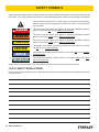
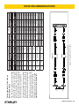
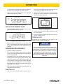
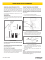
DS06
HYDRAULIC
DIAMOND SAW
USER MANUAL
Safety, Operation and Maintenance
© 2014 Stanley Black & Decker, Inc.
New Britain, CT 06053
U.S.A.
34566 2/2015 Ver. 10
DECLARATION OF CONFORMITY
DECLARATION OF CONFORMITY
ÜBEREINSTIMMUNGS-ERKLARUNG
DECLARATION DE CONFORMITE CEE
DECLARACION DE CONFORMIDAD
DICHIARAZIONE DI CONFORMITA
Hydraulic Tools
______________________________________________________________________
I, the undersigned:
Ich, der Unterzeichnende:
Je soussigné:
El abajo firmante:
lo sottoscritto:
Weisbeck, Andy
Surname and First names/Familiennname und Vornamen/Nom et prénom/Nombre y apellido/Cognome e nome
hereby declare that the equipment specified hereunder:
bestätige hiermit, daß erklaren Produkt genannten Werk oder Gerät:
déclare que l’équipement visé ci-dessous:
Por la presente declaro que el equipo se especifica a continuación:
Dichiaro che le apparecchiature specificate di seguito:
Concrete Cutting Chainsaw, Hydraulic
1.
Category:
Kategorie:
Catégorie:
Categoria:
Categoria:
2.
Make/Marke/Marque/Marca/Marca
3.
Type/Typ/Type/Tipo/Tipo:
4.
Serial number of equipment:
Seriennummer des Geräts:
Numéro de série de l’équipement:
Numero de serie del equipo:
Matricola dell´attrezzatura:
Stanley
DS06200001, DS06300001
All
Has been manufactured in conformity with
Wurde hergestellt in Übereinstimmung mit
Est fabriqué conformément
Ha sido fabricado de acuerdo con
E’ stata costruita in conformitá con
Directive/Standards
Richtlinie/Standards
Directives/Normes
Directriz/Los Normas
Direttiva/Norme
No.
Nr
Numéro
No
n.
Approved body
Prüfung durch
Organisme agréé
Aprobado
Collaudato
EN ISO
12100:2010
Self
EN ISO
ISO
ISO
Machinery Directive
3744:2010
20643:2005
10726:1992
2006/42/EC:2006
Self
Self
Self
Self
5.
Special Provisions:
None
Spezielle Bestimmungen:
Dispositions particulières:
Provisiones especiales:
Disposizioni speciali:
6.
Representative in the Union: Patrick Vervier, Stanley Dubuis 17-19, rue Jules Berthonneau-BP 3406 41034 Blois Cedex, France.
Vertreter in der Union/Représentant dans l’union/Representante en la Union/Rappresentante presso l’Unione
Done at/Ort/Fait à/Dado en/Fatto a Stanley Hydraulic Tools, Milwaukie, Oregon USA
Signature/Unterschrift/Signature/Firma/Firma
Position/Position/Fonction/Cargo/Posizione
2 ► DS06 User Manual
Director of Product Development
Date/Datum/le/Fecha/Data
1-4-11
TABLE OF CONTENTS
DECLARATION OF CONFORMITY...........................................................................................................................2
SAFETY SYMBOLS...................................................................................................................................................4
SAFETY PRECAUTIONS...........................................................................................................................................5
TOOL STICKERS & TAGS.........................................................................................................................................7
HOSE TYPES.............................................................................................................................................................8
HOSE RECOMMENDATIONS...................................................................................................................................9
HTMA REQUIREMENTS..........................................................................................................................................10
OPERATION............................................................................................................................................................. 11
MAINTENANCE & ADJUSTMENTS.........................................................................................................................14
TOOL PROTECTION & CARE.................................................................................................................................19
TROUBLESHOOTING.............................................................................................................................................20
DIAMOND CHAIN APPLICATIONS..........................................................................................................................21
SPECIFICATIONS....................................................................................................................................................22
ACCESSORIES.......................................................................................................................................................22
DS06 PARTS ILLUSTRATION.................................................................................................................................23
DS06 PARTS LIST...................................................................................................................................................24
IMPORTANT
To fill out a Product Warranty Validation form, and for information on your warranty,
visit Stanleyhydraulics.com and select the Company tab, Warranty.
(NOTE: The warranty Validation record must be submitted to validate the warranty).
SERVICING: This manual contains safety, operation, and routine maintenance instructions. Stanley Hydraulic Tools
recommends that servicing of hydraulic tools, other than routine maintenance, must be performed by an authorized
and certified dealer. Please read the following warning.
WARNING
SERIOUS INJURY OR DEATH COULD RESULT FROM THE IMPROPER REPAIR OR
SERVICE OF THIS TOOL.
REPAIRS AND / OR SERVICE TO THIS TOOL MUST ONLY BE DONE BY AN
AUTHORIZED AND CERTIFIED DEALER.
For the nearest authorized and certified dealer, call Stanley Hydraulic Tools at the number listed on the back of this
manual and ask for a Customer Service Representative.
DS06 User Manual ◄ 3
SAFETY SYMBOLS
Safety symbols and signal words, as shown below, are used to emphasize all operator, maintenance and repair actions which, if not strictly followed, could result in a life-threatening situation, bodily injury or damage to equipment.
This is the safety alert symbol. It is used to alert you to potential personal injury
hazards. Obey all safety messages that follow this symbol to avoid possible
injury or death.
DANGER
This safety alert and signal word indicate an imminently hazardous situation
which, if not avoided, will result in death or serious injury.
WARNING
This safety alert and signal word indicate a potentially hazardous situation
which, if not avoided, could result in death or serious injury.
CAUTION
This safety alert and signal word indicate a potentially hazardous situation
which, if not avoided, could result in death or serious injury.
CAUTION
This signal word indicates a potentially hazardous situation which, if not avoided, may result in property damage.
NOTICE
This signal word indicates a situation which, if not avoided, will result in damage
to the equipment.
IMPORTANT
This signal word indicates a situation which, if not avoided, may result in damage to the equipment.
Always observe safety symbols. They are included for your safety and for the protection of the tool.
LOCAL SAFETY REGULATIONS
Enter any local safety regulations here. Keep these instructions in an area accessible to the operator and maintenance personnel.
4 ► DS06 User Manual
SAFETY PRECAUTIONS
Tool operators and maintenance personnel must always
comply with the safety precautions given in this manual
and on the stickers and tags attached to the tool and
hose.
•
Do not rely exclusively upon the safety devices built
into the chain saw. As a chain saw user, several
steps must be taken to keep your cutting jobs free
from accident or injury:
These safety precautions are given for your safety. Review them carefully before operating the tool and before
performing general maintenance or repairs.
a. With a basic understanding of kickbacks, you
can reduce or eliminate the element of surprise.
Sudden surprise contributes to accidents.
Supervising personnel should develop additional precautions relating to the specific work area and local
safety regulations. If so, place the added precautions in
the space provided in this manual.
b. Keep a good firm grip on the chain saw with
both hands, the right hand on the rear handle
and the left hand on the front handle when operating the chain saw. Use a firm grip with thumbs
and fingers encircling the chain saw handles. A
firm grip helps reduce kickbacks and maintains
control of the chain saw. Do not let go.
The DS06 Diamond Saw will provide safe and dependable service if operated in accordance with the instructions given in this manual. Read and understand this
manual and any stickers and tags attached to the tool
and hoses before operation. Failure to do so could result
in personal injury or equipment damage.
c. Make sure the area in which you are cutting is
free of obstructions.
d. Cut at rated operating speeds (gpm).
e. Do not overreach or cut above shoulder height.
f. Only use replacement bars and chains specified
by Stanley or the equivalent.
•
Make sure the chain guard is in place before operating the chain saw.
•
Remove or control the water slurry to prevent yourself or others from slipping while cutting.
•
Provide adequate ventilation in closed areas when
operating a gas or diesel hydraulic power source.
•
Establish a training program for all operators to ensure safe operation.
•
The operator must be familiar with all prohibited
work areas such as excessive slopes and dangerous terrain conditions.
•
Do not operate the chain saw unless thoroughly
trained or under the supervision of an instructor.
•
Do not operate a hydraulic power source or a hydraulic diamond saw in an explosive atmosphere.
•
Always wear safety equipment such as goggles, ear,
breathing, head protection, leg protection, gloves,
snug fitting clothing and safety shoes at all times
when operating the chain saw.
•
•
Do not overreach. Maintain proper footing and balance at all times.
•
Do not inspect or clean the chain saw while the hydraulic power source is connected. Accidental engagement of the chain saw can cause serious injury.
•
Always connect hoses to the chain saw hose couplers before energizing the hydraulic power source.
Make sure all hose connections are tight.
Warning: Use of this tool on certain materials during
demolition could generate dust potentially containing a variety of hazardous substances such as asbestos, silica or lead. Inhalation of dust containing
these or other hazardous substances could result
in serious injury, cancer or death. Protect yourself
and those around you. Research and understand
the materials you are cutting. Follow correct safety
procedures and comply with all applicable national,
state or provisional health and safety regulations
relating to them, including, if appropriate arranging
for the safe disposal of the materials by a qualified
person.
•
Do not operate the chain saw at fluid temperatures
above 140 °F/60 °C. Operation at higher temperatures can cause higher than normal temperatures
at the chain saw which can result in operator discomfort.
•
DS06 User Manual ◄ 5
SAFETY PRECAUTIONS
•
Always be well rested and mentally alert before operating the chain saw.
•
Check all chain breaker and rivet spinner components regularly for wear and general condition.
•
Do not allow bystanders near the chain saw when
starting or cutting.
•
Avoid contact with the saw bar rails as they can become very sharp during use.
•
Do not start cutting until you have a clear work area
and secure footing.
•
Provide adequate lighting when operating the saw in
a darkened area or at night.
•
Keep all parts of the body away from the chain saw
during operation, including loose clothing and long
hair.
•
Always keep critical tool markings, such as labels
and warning stickers legible. Always replace stickers and decals that have become worn or damaged.
•
Carry the chain saw with the tool de-energized and
the bar and chain to the rear of your body.
•
•
Do not operate a chain saw that is damaged, improperly adjusted, or not completely and securely
assembled. Make sure the chain stops moving
when the control trigger is released.
Be observant of hydraulic and water hoses that lay
about the work area, especially in trenches where
they can be hidden from view due to liquids that
have accumulated within the space.
•
Keep all parts of the body away from the cleats that
are attached to the saw, as these are sharp and can
be a puncture hazard.
•
Improper handling, use, or maintenance can result
in an oil leak or burst. Do not contact an oil leak as
high pressure oil can cause injection into the body.
•
Never stand in the path of the discharge, as ejection
of material from the work piece can cause personal
injury.
•
Never use the saw in a potentially explosive atmosphere.
•
WARNING: Hydraulic fluid under pressure could
cause skin injection injury. If you are injured by
hydraulic fluid, get medical attention immediately.
•
Keep the handle dry, clean and free of hydraulic
fluid.
•
Do not use the chain saw near energized transmission lines.
•
Turn off the power source or move the hydraulic
control valve to neutral before setting the chain saw
down.
•
Use a guide bar scabbard when transporting the
chain saw.
•
Know the location of buried or covered utilities before starting work.
•
To avoid personal injury or equipment damage, all
chain saw repair, maintenance and service must
only be performed by authorized and properly
trained personnel.
•
Make sure the chain breaker and rivet spinner are
securely mounted on flat, clean work surfaces.
Check the mounting screws/bolts often.
6 ► DS06 User Manual
TOOL STICKERS & TAGS
Lwa
28323
CE Decal
11212
Sound Level Decal
11206
Circuit C Decal (5-GPM Models)
11207
Circuit D Decal (8-GPM models)
73659
Name Tag Decal
CAUTION
DANGER
7-9 GPM / 26-34 LPM
DO NOT EXCEED 2000 PSI / 140 BAR
Failure to use hydraulic hose labeled and certified
as non-conductive when using hydraulic tools on
DO NOT EXCEED SPECIFIED FLOW OR PRESSURE
USE CLOSED-CENTER TOOL ON CLOSED-CENTER
SYSTEM. USE OPEN-CENTER TOOL ON OPEN-CENTER
SYSTEM. CORRECTLY CONNECT HOSES TO TOOL “IN”
AND “OUT” PORTS. IMPROPER HANDLING, USE OR OTHER
MAINTENANCE OF TOOL COULD RESULT IN A LEAK, BURST
OR OTHER TOOL FAILURE. CONTACT AT A LEAK OR BURST
CAN CAUSE OIL INJECTION INTO THE BODY. FAILURE TO
OBSERVE THESE PRECAUTIONS CAN RESULT IN SERIOUS
PERSONAL INJURY.
or near electric lines may result in death or
serious injury.
For proper and safe operation read owners manual
and mwke sure that you have been properly
ELECTROCUTION
HAZARD
trained in correct procedures required for work
on or around electric lines.
12412
Warning Sticker–Electrical
28409
Composite Decal
03786
GPM sticker, 7–9 2000 psi
DS063000 only
NOTE:
THE INFORMATION LISTED
ON THE STICKERS SHOWN,
MUST BE LEGIBLE AT ALL
TIMES.
REPLACE DECALS IF
THEY BECOME WORN OR
DAMAGED. REPLACEMENTS
ARE AVAILABLE FROM
YOUR LOCAL STANLEY
DISTRIBUTOR.
The safety tag (P/N 15875) at right is
attached to the tool when shipped from
the factory. Read and understand the
safety instructions listed on this tag before
removal. We suggest you retain this tag and
attach it to the tool when not in use.
D A N G E R
1.
FAILURE TO USE HYDRAULIC HOSE LABELED AND CERTIFIED AS NON-CONDUCTIVE WHEN USING HYDRAULIC
TOOLS ON OR NEAR ELECTRICAL LINES MAY RESULT IN
DEATH OR SERIOUS INJURY.
BEFORE USING HOSE LABELED AND CERTIFIED AS NONCONDUCTIVE ON OR NEAR ELECTRIC LINES BE SURE THE
HOSE IS MAINTAINED AS NON-CONDUCTIVE. THE HOSE
SHOULD BE REGULARLY TESTED FOR ELECTRIC CURRENT LEAKAGE IN ACCORDANCE WITH YOUR SAFETY
DEPARTMENT INSTRUCTIONS.
2.
A HYDRAULIC LEAK OR BURST MAY CAUSE OIL INJECTION INTO THE BODY OR CAUSE OTHER SEVERE
PERSONAL INJURY.
A.
DO NOT EXCEED SPECIFIED FLOW AND PRESSURE
FOR THIS TOOL. EXCESS FLOW OR PRESSURE MAY
CAUSE A LEAK OR BURST.
B.
DO NOT EXCEED RATED WORKING PRESSURE OF
HYDRAULIC HOSE USED WITH THIS TOOL. EXCESS
PRESSURE MAY CAUSE A LEAK OR BURST.
C. CHECK TOOL HOSE COUPLERS AND CONNECTORS
DAILY FOR LEAKS. DO NOT FEEL FOR LEAKS WITH
YOUR HANDS. CONTACT WITH A LEAK MAY RESULT
IN SEVERE PERSONAL INJURY.
D A N G E R
D. DO NOT LIFT OR CARRY TOOL BY THE HOSES. DO
NOT ABUSE HOSE. DO NOT USE KINKED, TORN OR
DAMAGED HOSE.
3.
MAKE SURE HYDRAULIC HOSES ARE PROPERLY CONNECTED TO THE TOOL BEFORE PRESSURING SYSTEM.
SYSTEM PRESSURE HOSE MUST ALWAYS BE CONNECTED TO TOOL “IN” PORT. SYSTEM RETURN HOSE
MUST ALWAYS BE CONNECTED TO TOOL “OUT” PORT.
REVERSING CONNECTIONS MAY CAUSE REVERSE
TOOL OPERATION WHICH CAN RESULT IN SEVERE
PERSONAL INJURY.
4.
DO NOT CONNECT OPEN-CENTER TOOLS TO CLOSEDCENTER HYDRAULIC SYSTEMS. THIS MAY RESULT IN
LOSS OF OTHER HYDRAULIC FUNCTIONS POWERED BY
THE SAME SYSTEM AND/OR SEVERE PERSONAL INJURY.
5.
BYSTANDERS MAY BE INJURED IN YOUR WORK AREA.
KEEP BYSTANDERS CLEAR OF YOUR WORK AREA.
6.
WEAR HEARING, EYE, FOOT, HAND AND HEAD PROTECTION.
7.
TO AVOID PERSONAL INJURY OR EQUIPMENT DAMAGE,
ALL TOOL REPAIR MAINTENANCE AND SERVICE MUST
ONLY BE PERFORMED BY AUTHORIZED AND PROPERLY
TRAINED PERSONNEL.
I M P O R T A N T
I M P O R T A N T
READ OPERATION MANUAL AND
SAFETY INSTRUCTIONS FOR THIS
TOOL BEFORE USING IT.
READ OPERATION MANUAL AND
SAFETY INSTRUCTIONS FOR THIS
TOOL BEFORE USING IT.
USE ONLY PARTS AND REPAIR
PROCEDURES APPROVED BY
STANLEY AND DESCRIBED IN THE
OPERATION MANUAL.
USE ONLY PARTS AND REPAIR
PROCEDURES APPROVED BY
STANLEY AND DESCRIBED IN THE
OPERATION MANUAL.
TAG TO BE REMOVED ONLY BY
TOOL OPERATOR.
TAG TO BE REMOVED ONLY BY
TOOL OPERATOR.
SEE OTHER SIDE
SEE OTHER SIDE
SAFETY TAG P/N 15875 (Shown smaller then actual size)
DS06 User Manual ◄ 7
HOSE TYPES
The rated working pressure of the hydraulic hose must be equal to or higher than the relief valve setting on the hydraulic system. There are three types of hydraulic hose that meet this requirement and are authorized for use with
Stanley Hydraulic Tools. They are:
Certified non-conductive — constructed of thermoplastic or synthetic rubber inner tube, synthetic fiber braid
reinforcement, and weather resistant thermoplastic or synthetic rubber cover. Hose labeled certified nonconductive is the only hose authorized for use near electrical conductors.
Wire-braided (conductive) — constructed of synthetic rubber inner tube, single or double wire braid reinforcement, and weather resistant synthetic rubber cover. This hose is conductive and must never be used near
electrical conductors.
Fabric-braided (not certified or labeled non-conductive) — constructed of thermoplastic or synthetic rubber inner tube, synthetic fiber braid reinforcement, and weather resistant thermoplastic or synthetic rubber cover. This
hose is not certified non-conductive and must never be used near electrical conductors.
HOSE SAFETY TAGS
To help ensure your safety, the following DANGER tags are attached to all hose purchased from Stanley Hydraulic
Tools. DO NOT REMOVE THESE TAGS.
If the information on a tag is illegible because of wear or damage, replace the tag immediately. A new tag may be
obtained from your Stanley Distributor.
D A N G E R
D A N G E R
1.
FAILURE TO USE HYDRAULIC HOSE LABELED AND CERTIFIED AS NON-CONDUCTIVE
WHEN USING HYDRAULIC TOOLS ON OR NEAR ELECTRIC LINES MAY RESULT IN
DEATH OR SERIOUS INJURY.
FOR PROPER AND SAFE OPERATION MAKE SURE THAT YOU HAVE BEEN PROPERLY TRAINED IN CORRECT PROCEDURES REQUIRED FOR WORK ON OR AROUND
ELECTRIC LINES.
2.
BEFORE USING HYDRAULIC HOSE LABELED AND CERTIFIED AS NON-CONDUCTIVE
ON OR NEAR ELECTRIC LINES. WIPE THE ENTIRE LENGTH OF THE HOSE AND FITTING WITH A CLEAN DRY ABSORBENT CLOTH TO REMOVE DIRT AND MOISTURE AND
TEST HOSE FOR MAXIMUM ALLOWABLE CURRENT LEAKAGE IN ACCORDANCE WITH
SAFETY DEPARTMENT INSTRUCTIONS.
3.
DO NOT EXCEED HOSE WORKING PRESSURE OR ABUSE HOSE. IMPROPER USE
OR HANDLING OF HOSE COULD RESULT IN BURST OR OTHER HOSE FAILURE.
KEEP HOSE AS FAR AWAY AS POSSIBLE FROM BODY AND DO NOT PERMIT DIRECT
CONTACT DURING USE. CONTACT AT THE BURST CAN CAUSE BODILY INJECTION
AND SEVERE PERSONAL INJURY.
4.
HANDLE AND ROUTE HOSE CAREFULLY TO AVOID KINKING, ABRASION, CUTTING, OR
CONTACT WITH HIGH TEMPERATURE SURFACES. DO NOT USE IF KINKED. DO NOT
USE HOSE TO PULL OR LIFT TOOLS, POWER UNITS, ETC.
5.
CHECK ENTIRE HOSE FOR CUTS CRACKS LEAKS ABRASIONS, BULGES, OR DAMAGE TO COUPLINGS IF ANY OF THESE CONDITIONS EXIST, REPLACE THE HOSE
IMMEDIATELY. NEVER USE TAPE OR ANY DEVICE TO ATTEMPT TO MEND THE HOSE.
6.
AFTER EACH USE STORE IN A CLEAN DRY AREA.
SEE OTHER SIDE
SIDE 1
SEE OTHER SIDE
(Shown smaller than actual size)
DO NOT REMOVE THIS TAG
DO NOT REMOVE THIS TAG
THE TAG SHOWN BELOW IS ATTACHED TO “CERTIFIED NON-CONDUCTIVE” HOSE
SIDE 2
D A N G E R
D A N G E R
1.
DO NOT USE THIS HYDRAULIC HOSE ON OR NEAR ELECTRIC LINES. THIS HOSE IS
NOT LABELED OR CERTIFIED AS NON-CONDUCTIVE. USING THIS HOSE ON OR NEAR
ELECTRICAL LINES MAY RESULT IN DEATH OR SERIOUS INJURY.
5.
CHECK ENTIRE HOSE FOR CUTS CRACKS LEAKS ABRASIONS, BULGES, OR DAMAGE TO
COUPLINGS IF ANY OF THESE CONDITIONS EXIST, REPLACE THE HOSE IMMEDIATELY.
NEVER USE TAPE OR ANY DEVICE TO ATTEMPT TO MEND THE HOSE.
2.
FOR PROPER AND SAFE OPERATION MAKE SURE THAT YOU HAVE BEEN PROPERLY
TRAINED IN CORRECT PROCEDURES REQUIRED FOR WORK ON OR AROUND ELECTRIC LINES.
6.
AFTER EACH USE STORE IN A CLEAN DRY AREA.
3.
DO NOT EXCEED HOSE WORKING PRESSURE OR ABUSE HOSE. IMPROPER USE OR
HANDLING OF HOSE COULD RESULT IN BURST OR OTHER HOSE FAILURE. KEEP HOSE
AS FAR AWAY AS POSSIBLE FROM BODY AND DO NOT PERMIT DIRECT CONTACT
DURING USE. CONTACT AT THE BURST CAN CAUSE BODILY INJECTION AND SEVERE
PERSONAL INJURY.
4.
HANDLE AND ROUTE HOSE CAREFULLY TO AVOID KINKING, CUTTING, OR CONTACT
WITH HIGH TEMPERATURE SURFACES. DO NOT USE IF KINKED. DO NOT USE HOSE TO
PULL OR LIFT TOOLS, POWER UNITS, ETC.
SEE OTHER SIDE
SEE OTHER SIDE
SIDE 1
SIDE 2
(Shown smaller than actual size)
8 ► DS06 User Manual
DO NOT REMOVE THIS TAG
DO NOT REMOVE THIS TAG
THE TAG SHOWN BELOW IS ATTACHED TO “CONDUCTIVE” HOSE.
All hydraulic hose must meet or exceed
specifications as set forth by SAE J517.
All hydraulic hose must have at least a rated
minimum working pressure equal to the maximum hydraulic system relief valve setting.
This chart is intended to be used for hydraulic
tool applications only based on Stanley Hydraulic Tools tool operating requirements and
should not be used for any other applications.
The chart to the right shows recommended
minimum hose diameters for various hose
lengths based on gallons per minute (gpm)/
liters per minute (lpm). These recommendations are intended to keep return line pressure
(back pressure) to a minimum acceptable level to ensure maximum tool performance.
Tool to Hydraulic Circuit Hose
Recommendations
15-34
MM
Inside Diameter
INCH
USE
(Press/Return)
PSI
up to 10
up to 3
3/8
10
Both
2250
49-60
13-16
FLOW >>>
RETURN
<<< FLOW
PRESSURE
26-100
up to 25
100-200
51-100
up to 50
100-300
51-100
up to 50
26-100
up to 25
8-30
up to 8
30-60
15-30
up to 15
30-90
15-30
up to 15
7.5-30
up to 7.5
Figure 1. Typical Hose Connections
49-60
38-49
10-13
13-16
19-40
5-10.5
38-49
19-40
5-10.5
10-13
19-40
5-10.5
38-49
15-23
10-13
15-23
4-6
19
25.4
16
19
19
25.4
5/8
3/4
3/4
1
19
3/4
1
16
3/4
16
19
3/4
5/8
16
5/8
5/8
16
13
13
10
5/8
1/2
1/2
3/8
Return
Pressure
Return
Pressure
Return
Pressure
Return
Pressure
Both
Return
Pressure
Both
Both
Both
Both
2500
2500
2500
2500
2500
2500
2500
2500
2500
2500
2500
2500
2500
2500
2500
175
175
175
175
175
175
175
175
175
175
175
175
175
175
175
155
BAR
Min. Working Pressure
Certified Non-Conductive Hose - Fiber Braid - for Utility Bucket Trucks
METERS
Hose Lengths
FEET
Conductive Hose - Wire Braid or Fiber Braid -DO NOT USE NEAR ELECTRICAL CONDUCTORS
4-6
4-9
LPM
Oil Flow
GPM
HOSE RECOMMENDATIONS
DS06 User Manual ◄ 9
HTMA / EHTMA REQUIREMENTS
HTMA / EHTMA REQUIREMENTS
HTMA
HYDRAULIC SYSTEM REQUIREMENTS
TYPE I
Nominal Operating Pressure
(at the power supply outlet)
4-6 gpm
(15-23 lpm)
1500 psi
(103 bar)
TOOL TYPE
TYPE II
TYPE RR
7-9 gpm
(26-34 lpm)
1500 psi
(103 bar)
9-10.5 gpm
(34-40 lpm)
1500 psi
(103 bar)
System relief valve setting
(at the power supply outlet)
2100-2250 psi
(145-155 bar)
2100-2250 psi
(145-155 bar)
2200-2300 psi
(152-159 bar)
2100-2250 psi
(145-155 bar)
Maximum back pressure
(at tool end of the return hose)
250 psi
(17 bar)
250 psi
(17 bar)
250 psi
(17 bar)
250 psi
(17 bar)
Measured at a max. fluid viscosity of:
(at min. operating temperature)
400 ssu*
400 ssu*
400 ssu*
400 ssu*
(82 centistokes) (82 centistokes) (82 centistokes) (82 centistokes)
Temperature: Sufficient heat rejection
capacity to limit max. fluid temperature to:
(at max. expected ambient temperature)
140° F
(60° C)
Flow Range
140° F
(60° C)
140° F
(60° C)
TYPE III
11-13 gpm
(42-49 lpm)
1500 psi
(103 bar)
140° F
(60° C)
3 hp
5 hp
6 hp
7 hp
Min. cooling capacity at a temperature
(2.24 kW)
(3.73 kW)
(5.22 kW)
(4.47 kW)
difference of between ambient and fluid
40° F
40° F
40° F
40° F
temps
(22° C)
(22° C)
(22° C)
(22° C)
NOTE:
Do not operate the tool at oil temperatures above 140° F (60° C). Operation at higher temperatures can cause operator
discomfort at the tool.
Filter
Min. full-flow filtration
Sized for flow of at least:
(For cold temp. startup and max.
dirt-holding capacity)
25 microns
30 gpm
(114 lpm)
Hydraulic fluid Petroleum based
(premium grade, anti-wear, non-conductive)
Viscosity (at min. and max. operating temps)
100-400 ssu*
25 microns
30 gpm
(114 lpm)
25 microns
30 gpm
(114 lpm)
100-400 ssu*
100-400 ssu*
(20-82 centistokes)
25 microns
30 gpm
(114 lpm)
100-400 ssu*
NOTE:
When choosing hydraulic fluid, the expected oil temperature extremes that will be experienced in service determine the
most suitable temperature viscosity characteristics. Hydraulic fluids with a viscosity index over 140 will meet the requirements
over a wide range of operating temperatures.
*SSU = Saybolt Seconds Universal
EHTMA
HYDRAULIC SYSTEM
REQUIREMENTS
CLASSIFICATION
B
C
D
Nominal Operating Pressure
(at the power supply outlet)
3.5-4.3 gpm
(13.5-16.5 lpm)
1870 psi
(129 bar)
4.7-5.8 gpm
(18-22 lpm)
1500 psi
(103 bar)
7.1-8.7 gpm
(27-33 lpm)
1500 psi
(103 bar)
9.5-11.6 gpm
(36-44 lpm)
1500 psi
(103 bar)
11.8-14.5 gpm
(45-55 lpm)
1500 psi
(103 bar)
System relief valve setting
(at the power supply outlet)
2495 psi
(172 bar)
2000 psi
(138 bar)
2000 psi
(138 bar)
2000 psi
(138 bar)
2000 psi
(138 bar)
Flow Range
NOTE: These are general hydraulic system requirements. See tool specification page for tool specific requirements
10 ► DS06 User Manual
OPERATION
PRE-OPERTION PROCEDURES
CHECK THE POWER SOURCE
1. Using a calibrated flow meter and pressure gauge,
make sure the hydraulic power source develops a
flow of 7–9 gpm/26–34 lpm for the 8 gpm model and
4–6 gpm/15–23 lpm for the 5 gpm model at 2000
psi/140 bar.
2. Make certain that the power source is equipped with
a relief valve set to open at 2100–2250 psi/145–155
bar.
3. Check that the hydraulic circuit matches the tool for
open-center (OC) or closed-center (CC) operation.
The DS06 is designed for open-center operation
only.
CHECK TOOL
1. Make sure all tool accessories are correctly installed. Failure to install tool accessories properly
can result in damage to the tool or personal injury.
2. There should be no signs of leaks.
3. The tool should be clean, with all fittings and fasteners tight.
4. Observe the arrow on the couplers to ensure that
the hydraulic oil flow is in the proper direction. The
female coupler is the inlet (pressure) coupler.
5. Check that the trigger operates smoothly and is free
to travel between the ON and OFF positions.
6. Check that the chain is properly installed. The chain
is designed to only operate in one direction. Make
sure the chain is installed so the bumper guard precedes each diamond segment. See Figure 2.
Segment
Bumper
Guard
CORRECT
CONNECT HYDRAULIC HOSES
1. Wipe all hose couplers with a clean lint-free cloth
before making connections. If necessary, use a
light-weight penetrating oil in a spray can to clean
the hose couplers before each connection.
2. Connect the hoses from the hydraulic power source
to the chain saw fittings or quick disconnects. It is a
good practice to connect return hose first and disconnect them last to minimize or avoid trapped pressure within the chain saw.
3. Observe the arrow on the couplers to ensure that
the flow is in the proper direction. The female coupler on the chain saw is the inlet (pressure) coupler.
NOTE:
If uncoupled hoses are left in the sun, pressure increase inside the hoses might make them difficult to
connect. Whenever possible, connect the free ends
of the hoses together.
CONNECTING TO A WATER SUPPLY
1. Using a standard garden hose, connect the DS06 to
a city or auxiliary water supply. Make sure the flow is
at least 4 gpm/15 lpm at 50 psi/3.5 bar.
IMPORTANT
Chain and bar damage will occur if the tool operates
without the proper water supply and water pressure.
2. Make sure the water is running before starting the
tool.
3. If a water pump is being used, refer to the manufacturers instructions for use of the pump. Make
sure the pump produces a minimum water flow of 4
gpm/15 lpm at 50 psi/3.5 bar and the water pressure
does not exceed 160 psi/11 bar.
CHECK CHAIN AND BAR ADJUSTMENT
NOTE:
Check the chain tension often during operation, especially during the first 1/2 hour when using a new
chain. Adjust the chain accordingly when it becomes
loose. Follow the procedures contained in the Maintenance and Adjustments section of this manual.
INCORRECT
Figure 2. Chain Direction
1. Make sure the chain does not exceed a clearance of
5/16 in./8 mm from the bar (see Figure 3). Exceed-
DS06 User Manual ◄ 11
OPERATION
ing the maximum clearance increases the chance of
the chain being dislodged from the bar groove.
keep from pinching the saw bar and chain as a result of falling pieces of concrete, brick, etc.
2. Make sure the bar attaching nuts are fully tightened
and the chain guard is in place.
2. Make your cuts in the order shown in Figure 5, starting with cut 1 (base horizontal cut) and proceeding
with the remaining three cuts.
Bottom of Bar
Max
5/16"
Figure 3. Maximum Chain Clearance
CHECK CHAIN SEGMENT WEAR
1. Using adjustable calipers, measure several chain
segments as illustrated in Figure 4.
Bottom of Bar
Min.
1/16"
Figure 4. Chain Segment Wear
2. If the average measurement is less than 1/16inch/1.6 mm, then the chain must be replaced. Refer
to your Service Manual for chain replacement procedures.
OPERATING PROCEDURES
1. Observe all safety precautions.
2. Turn on the water supply. Water at the tool will be
directed to the bar and chain when the trigger on the
tool is squeezed ON.
3. Operate the tool for two minutes away from the intended cut and then check the chain tension. New
chain will normally stretch during its first usage. It is
very important to keep the chain tension adjusted
so that it does not exceed 5/16 in./8 mm clearance
from the bottom of the bar. See Check Chain & Bar
Adjustment in this manual.
4. If the chain requires adjustment, see Maintenance &
Adjustments in this manual.
PLAN THE CUT
1. Plan your cuts to prevent injury to yourself and to
12 ► DS06 User Manual
Figure 5. Planning Cuts
3. Outline the concrete area with a permanent marker
for a visual guide.
4. Know what kind of material and how much reinforcing you are going to cut.
TYPES OF CUTS
The DS06 can be operated using the types of cuts
shown in Figure 6. When making cuts:
NOTICE
The following are general cutting procedures and
techniques. Differences in the terrain and the type of
material being cut will make this information more or
less valid for particular areas. For advice on specific
cutting problems or techniques, consult your local
Stanley Representative. He/she can often provide
information that will make your work safer and more
productive.
OPERATION
hydraulic fluid at low power source speed. When using
the normally recommended fluids, fluid should be at or
above 50 °F/10 °C (400 ssu/82 centistokes) before use.
DOWN CUT
Damage to the hydraulic system or chain saw can result
from use with fluid that is too viscous or thick.
USING THE WALL WALKER™
The Wall Walker™ lessens operator fatigue and effort
during cutting by automatic insertion of the wedge into
the cut, thus allowing the operator to apply leverage to
the saw.
PLUNGE CUT
1. Position the Wall Walker™ in the "autofeed" position
by pinning the lever arm at the lowest hole as shown
in the illustration.
Start cutting with the DS06 until the cut is large
enough to allow the tip of the wedge to insert into the
cut. With the tip of the wedge in the cut, the operator can easily apply leverage to the saw which will
aid the cutting process and lessen operator fatigue
and effort.
UP CUT
Figure 6. Types of Cuts (chain guard removed for
clarity)
1. Do not use a cutting force in excess of 45 lbs/20
kg. Excessive force causes the chain to slow down
or stall and causes premature wear of the saw bar
and chain.
After the saw cuts approximately 1 to 2.5 in./25 to
65 mm, withdraw the saw only enough to allow the
lever arm and wedge to reposition. After repositioning, continue cutting.
2. The Wall Walker™ can be positioned to the “parked”
position by pinning the lever arm at the upper most
hole. In this position, the Wall Walker™ is used as a
bucking cleat.
2. Always maintain a high chain speed. High chain
speeds produce the best results.
3. Always check that plenty of water is being expelled
from the bar and chain. When the tool is running,
water is directed to the interior of the bar and then
out of several holes located along the top and bottom channels on the bar. If these holes become
plugged, cutting debris will not be adequately
washed away and will result in premature wear of
the bar and chain.
4. Avoid aggressive/heavy plunge forces. Aggressive
plunge force creates fragmenting of the concrete
when the saw bar and chain exits and causes premature bar and chain wear.
COLD WEATHER OPERATION
If the saw is to be used during cold weather, preheat the
Wall Walker™ Lever Arm
(Shown in “autofeed position)
Figure 7. Wall Walker™
DS06 User Manual ◄ 13
MAINTENAN & ADJUSTMENTS
GENERAL MAINTENANCE TIPS
CHAIN TENSION ADJUSTMENT
Several simple maintenance tasks which, if performed,
can keep a chain saw operating at a high level of efficiency. Routine maintenance also keeps replacement
costs down on the parts of the chain saw, which occasionally wear out.
Correct chain tension is very important throughout the
life of the chain. Check the chain tension often during
use (when the chain saw is stopped and the saw bar and
chain have cooled off). The chain should move easily
around the saw bar when pulled by hand. To adjust the
chain tension:
If any chain saw disassembly is required, refer to the
Service Manual.
SAW BAR RAIL
1. Turn off the water and power supplies.
2. Loosen the two saw bar attachment nuts (Figure 9).
A quick check can be made to determine if saw bar rail
or chain segment wear exists. Figure 8 shows a worn
saw bar rail.
Bar Attachment
Nuts (2)
Bar Adjusting Screw
Figure 9. Attachment Screw Locations
3. Using the saw bar adjustment screw (Item 68, Parts
Illustration), tighten the chain until you are still able
to rotate it one full revolution by hand (Figure 10).
Figure 8. Rail Wear
If the saw bar rails are worn, use a flat file and dress
each one until it is flat and square with the side of the
saw bar (Figure 8).
Also make sure the saw bar is perfectly straight. If bows
or bends are present in the saw bar, it must be replaced
before dressing any rail.
ROTATING THE SAW BAR
Maximum saw bar life can be achieved by occasionally
turning the bar over so the top and bottom bar surfaces
wear evenly. Refer to the saw bar disassembly procedures in the Service Manual for further details.
14 ► DS06 User Manual
Figure 10. Pulling the Chain
4. Pull the chain around the saw bar to make sure it
properly fits the sprocket and saw bar. The chain
should be easily pulled.
5. Fully tighten the two saw bar attachment nuts
(Figure 9).
NOTE:
Adjust the chain tension each time the drive link
tang hangs fully exposed from the groove at the bottom of the saw bar (Figure 11).
MAINTENAN & ADJUSTMENTS
Max
5/16"
Bottom of Bar
Figure 11. Exposed Drive Link Tang
SERVICING THE CHAIN
The following procedures explain how to break a chain
using Stanley’s bench mounted chain breaker (P/N
20858) to remove a worn or damaged segment.
1. Mount the chain breaker flush with the side or front
of a flat, clean work surface (Figure 12).
Figure 14. Inserting the Chain
3. Position the rivet head you want removed directly
under the chain-breaker punch and then pull the
handle down far enough to remove the rivet (Figure
15). Do not use excessive force.
Figure 12. Chain Breaker Mounting
NOTE:
The Stanley chain breaker is only designed to remove rivet heads from the connecting links, not
from a chain segment. The rivet heads shown in the
shaded areas of Figure 13 are the only ones that can
be removed.
Figure 15. Removing a Rivet
Figure 13. Removable Rivet Heads
2. Place the chain (the portion that you want broken)
into the slot of the anvil pushing it forward until the
bottom connecting link is flush with the far side of
the slot (Figure 14).
DS06 User Manual ◄ 15
MAINTENAN & ADJUSTMENTS
REPLACING THE CHAIN BREAKER
PUNCH
If the chain breaker punch (P/N 22801) becomes worn
or damaged, use the following procedures for replacement.
1. Remove the punch by loosening the set screw
(Figure 16).
Figure 18. Rivet Spinner Mounting
2. Lay the chain across the plastic chain supports and
then rotate the supports so the rivet head is centered between the take-up handle pocket and the
spinner anvil (Figure 19).
Figure 16. Removing the Punch
2. Insert a new punch into the holder and push it up
until it is fully seated (Figure 17). Secure the punch
to the chain breaker holder by fully tightening the
set screw.
Figure 19. Positioning the Chain
3. Turn the take-up handle until the chain is tight
against the spinner anvil (Figure 20).
Rivet Spinner
Crank
Take-up
Handle
Figure 17. Replacing the Punch
SPINNING RIVETS
The following procedures explain how to spin rivets using Stanley’s bench-mounted rivet spinner (P/N 20857)
to assembly the chain.
1. Mount the rivet spinner flush with the side or front of
a flat, clean work surface (Figure 18).
Figure 20. Securing the Chain
4. Turn the rivet spinner crank a few times to center the
rivet hub in the spinner anvil (Figure 21).
Rivet Spinner
Crank
Figure 21. Centering the Rivet Hub
16 ► DS06 User Manual
Take-up
Handle
MAINTENAN & ADJUSTMENTS
5. Apply a few drops of oil to the rivet hub (Figure 22).
NOSE SPROCKET DISASSEMBLY
AND ASSEMBLY
1. Using the bench mounted chain breaker (see accessories), line up the 1/4 inch hole in the side of the
chain breaker anvil with the chain breaker punch.
Punch out the six nose sprocket rivets. See Figure
25.
Figure 22. Applying the Oil
6. Turn the spinner crank while slowly running the takeup handle inward (approximately one full revolution)
until the rivet head is formed (Figure 23).
NOTE:
The take-up handle provides pressure while the
spinner anvil forms the rivet head.
Figure 25. Punching Out Nose Sprocket Rivets
2. Insert a straight blade screw driver to spread the
bar nose rails just enough to remove the old nose
sprocket. Use a rag or paper towel to clean the nose
sprocket area. See Figure 26.
Figure 23. Forming a Rivet Head
Figure 26. Removing Old Nose Sprocket
Figure 24. Spinner Oiling Chambers
NOTE:
The rivet spinner is equipped with oiling chambers
and should be maintained periodically with a lightweight oil (Figure 24).
DS06 User Manual ◄ 17
MAINTENAN & ADJUSTMENTS
3. Remove the new nose sprocket package's clips and
fold back the top portion of the insertion card being careful not to remove or disturb the components.
See Figure 27.
6. With the bar and rivets solidly supported on a strong
flat steel surface, carefully peen the rivet heads
down with the flat end of a hammer. Be careful to
only hit the rivet head. Do not hit the bar body; this
will pinch the nose sprocket. Rivet heads must completely fill the countersinks in the bar body and be
snug and secure while still allowing the sprocket to
freely turn. See Figure 29.
Figure 27. Preparing New Nose Sprocket
4. With a flat blade screw driver in the bar nose rails,
slide the nose sprocket assembly into position aligning the 6 holes in the bar nose with the 6 holes in
the nose sprocket assembly without removing the
components from the card. See Figure 28.
Figure 29. Replacing Rivets
7. Using a flat file, shave the rivet heads to a uniform
height that is as close to the bar body as possible.
See Figure 30
Figure 28. Installing a New Nose Sprocket
5. Insert 6 nose rivets into the holes and then hold
them with your thumb. Remove the screwdriver and
slide out the insertion card.
NOTE:
On used bars the nose rails might tend to spread
apart. Use a small clamp if necessary to hold the
rails together.
18 ► DS06 User Manual
Figure 30. Filing Rivets
TOOL PROTECTION & CARE
NOTICE
In addition to the Safety Precautions found in
this manual, observe the following for equipment
protection and care.
•
Make sure all couplers are wiped clean before connection.
•
Always keep critical tool markings, such as warning
stickers and tags legible.
•
The hydraulic circuit control valve must be in the
OFF position when coupling or uncoupling hydraulic tools. Failure to do so may result in damage to
the quick couplers and cause overheating of the hydraulic system.
•
Tool repair should be performed by experienced
personnel only.
•
Make certain that the recommended relief valves
are installed in the pressure side of the system.
•
Do not use the tool for applications for which it was
not intended.
•
Always store the tool in a clean dry space, safe from
damage or pilferage.
•
Make sure the circuit PRESSURE hose (with male
quick disconnect) is connected to the IN port. The
circuit RETURN hose (with female quick disconnect)
is connected to the opposite port. Do not reverse circuit flow. This can cause damage to internal seals.
•
Always replace hoses, couplings and other parts
with replacement parts recommended by Stanley
Hydraulic Tools. Supply hoses must have a minimum working pressure rating of 2500 psi/172 bar.
•
Do not exceed the rated flow (see Specifications)
page in this manual for correct flow rate and model
number. Rapid failure of the internal seals may result.
DS06 User Manual ◄ 19
TROUBLESHOOTING
If symptoms of poor performance develop, the following chart can be used as a guide to correct the problem.
When diagnosing faults in operation of the tool, always check that the hydraulic power source is supplying the correct hydraulic flow and pressure to the tool as listed in the table. Use a flowmeter known to be accurate. Check the
flow with the hydraulic oil temperature at least 80 °F/27 °C.
SYMPTOM
Tool does not run.
CAUSE
SOLUTION
Hydraulic power source not
functioning correctly.
Check power source for proper flow and
pressure (7–9 gpm 26–34 lpm at 2000
psi/140 bar.
Coupler or hoses blocked.
Remove obstruction.
Mechanical failure.
Have tool serviced by authorized dealer.
Tool runs backwards.
Pressure and return lines incorrectly
connected.
Correct hose connections. Motor shaft
rotates counterclockwise as viewed from
the end of the motor shaft.
Diamond saw cuts slow.
Insufficient fluid flow or too high
back pressure or relief valve set too
low.
Check hydraulic supply. If hydraulic
supply is correct, have unit serviced by
authorized dealer.
Back pressure too high.
Should not exceed 250 psi/17 bar at 9
gpm/34 lpm measured at the end of the
tools operating hoses.
Loss of diamond segment side
clearance.
Replace chain.
Chain segment dulled because of
continuous use in hard material or
rebar.
Redress segmented by cutting in
abrasive material (i.e. concrete, building
block, etc.). NOTE: This indicates that
the wrong chain is being used.
Wrong chain for application.
Scale down to a lower numbered chain.
Wired edged bar rails.
Dress rails square.
Hydraulic fluid mixed in water
supply.
Have tool serviced.
Segment(s) broken or missing.
Repair broken segment or replace chain.
Chain installed backwards.
Correct chain direction.
Loose chain tension.
Re-tension the chain.
Excessive feed force.
Reduce feed force.
Will not cut straight.
Accumulated saw bar wear and
uneven chain segment profile wear.
Turn the saw bar over and dress rails
square. Replace the saw bar and chain.
Loss of power.
Drive sprocket slipping on
Trantorque® adapter.
Adjust and tighten Trantorque® adapter
to 17 ft lb/23 Nm.
Trigger hard to press.
Pressure and return hose reversed.
Connect for proper flow direction. Motor
shaft must rotate clockwise.
Back-pressure too high.
Should not exceed 250 psi/17 bar @ 9
gpm/34 lpm measured at the end of the
tool’s operating hoses.
Excessive vibration and cuts
rough.
20 ► DS06 User Manual
TROUBLESHOOTING
SYMPTOM
No water discharge at bar.
CAUSE
SOLUTION
Blocked port(s) in bar.
Turn off hydraulic supply. Remove bar
and chain and clean bar thoroughly.
Blow ports with compressed air.
Blocked inlet or outlet.
Turn off hydraulic supply. Remove bar
and chain. Make sure water supply is on.
Press trigger to see if water exits near bar
adjustment nut area (a small port). If no
water exits, have unit serviced.
DIAMOND CHAIN APPLICATIONS
MODEL
BAR LENGTH
P/N
CORRECT APPLICATIONS
Pinnacle-
13 inch
Very hard aggregate concretes (flint, chert, granite, etc). Heavy
steel reinforcing, 5/8 inch/16 mm diameter and larger. Medium/
hard aggregate concretes (granite, quartz, river rock, etc). Moderate
steel reinforcing (wire mesh 3/8-1/2 inch/10-12 mm diameter). Soft
aggregate concrete, concrete block, masonry, “green” concrete, highly
abrasive conditions.
Ultra-
13 inch
Medium/hard aggregate concretes (granite, quartz, river rock,
etc). Moderate steel reinforcing (wire mesh 3/8-1/2 inch/10-12 mm
diameter). Soft aggregate concrete, concrete block, masonry, “green”
concrete, highly abrasive conditions.
DS06 User Manual ◄ 21
SPECIFICATIONS
Cutting Depths....................................................................................................................................13 inches/33 cm
Bar Lengths............................................................................................................................................13 inch/33 cm
Chain Type..................................................................................................3/8 inch pitch with 21 diamond segments
Maximum Back Pressure...................................................................................................................... 250 psi/17 bar
Input Flow Range
5 gpm model............................................................................................................................. 4–6 gpm/15–23 lpm
8 gpm model............................................................................................................................. 7–9 gpm/26–34 lpm
Input Pressure................................................................................................................................... 2000 psi/140 bar
Weight (without bar)....................................................................................................................................14 lbs/6 kg
Length (without bar)........................................................................................................................14.3 inches/36 cm
Width....................................................................................................................................................9 inches/23 cm
Lubrication/Cooling......................................................................................................Internal Water Channels in Bar
Porting....................................................................................................................................................-8 SAE O-ring
Connection.........................................................................................................................EHTMA/HTMA Flush Face
Hose Whips............................................................................................................................................................ Yes
Chain Speed
5 gpm model............................................................................................................................... 4600 fpm/23.4 m/s
8 gpm model............................................................................................................................... 5000 fpm/25.4 m/s
SOUND POWER AND VIBRATION DECLARATION
Measured A-weighted sound power level, Lwa (ref. 1pW) in decibels
Uncertainty, Kwa, in decibels
Measured A-weighted sound pressure level, Lpa (ref. 20 µPa) at operator’s position, in decibels
Uncertainty, Kpa, in decibels
106.2 dBA
3 dBA
98.2 dBA
3 dBA
Values determined according to noise test code given in ISO 15744, using the basic standard
ISO 3744
NOTE:
The sum of a measured noise emission value and its associated uncertainty represents
an upper boundary of the range of values which is likely to occur in measurements.
Declared vibration emission value in accordance with EN 12096
Measured vibration emission value: a
6.0 m/sec²
Uncertainty: K
2.0 m/sec²
Values determined according to ISO 8662-1, ISO 5349-1,2
ACCESSORIES
Chain Repair Spinner.........................................................................................................................................20857
Diamond Chain Repair Breaker.........................................................................................................................20858
Diamond Chain Service Kit ................................................................................................(sub P/N 20857 or 20858)
Diamond Chain Butterfly Repair Kit....................................................................................................................20859
13 inch Bar, Sprocket Nose................................................................................................................................35037
Ultra-25, Diamond Chain for 13 inch Bar...........................................................................................................56799
Pinnacle-25, Diamond Chain for 13 inch Bar.....................................................................................................56800
Water Flow Meter, 0-7 gpm................................................................................................................................60859
Water Pump, 12 VDC, DC Plug.................................................................................................................. DCP30100
Water Pump, 12 VDC, Battery Clips........................................................................................................... DCP30101
22 ► DS06 User Manual
DS06 PARTS ILLUSTRATION
54
DS06 User Manual ◄ 23
DS06 PARTS LIST
ITEM
PART
NO.
QTY
DESCRIPTION
ITEM
PART
NO.
QTY
DESCRIPTION
1
00753
8
HSHCS 10-24 UNC × 1-1/4
41
36259
1
STEEL BALL, 3/8" DIA.
2
73659
1
NAME TAG
42
32188
1
SPRING
3
11207
1
CIRCUIT D DECAL (8-GPM MODEL)
43
04052
1
O-RING
CIRCUIT C DECAL (5-GPM MODEL)
44
32189
1
SEAL CAP
REAR GEAR HOUSING ASSY
(INCL ITEMS 5–6, 8-GPM MODEL ONLY)
45
28323
1
CE DECAL
46
—
—
NO ITEM
47
38898
1
SEAL SPACER
48
09098
1
SPROCKET
49
41765
1
WASHER
50
73658
1
CHAIN GUARD
51
32203
2
NUT
52
20721
1
CORD STOCK, 3/16" DIA.
53
43690
1
MOTOR SHAFT (SEE ITEM #60 FOR
SERIAL NO. BREAK)
54
04044
2
NEEDLE ROLLER
55
02688
1
HSHCS 5/16 -18 UNC × 3/4
56
60804
1
O-RING
57
19215
1
SEAL BACK-UP WASHER
58
43689
1
SPROCKET ADAPTER
59
58969
1
WIPER SEAL
60
66299
1
SPIRAL RETAINER RING
61
—
—
SAW BAR (SEE ACCESSORIES)
62
—
—
NO ITEM
63
32196
1
FLAP MOUNT
64
33219
1
SPACER
65
32192
1
CHAIN GUIDE PLATE
66
32245
1
STUD (SUPPLIED W/ ITEM 22)
67
58968
2
HSHCS 1/4 -20 UNC × 5/8
68
02687
1
MACHINE SCREW
69
32191
1
STAT-O-SEAL
70
32198
1
BAR ADJUSTMENT NUT
71
33481
1
WALL WALKER CLEVIS PIN
72
—
—
SPRING (INCL W/ ITEM 74)
73
—
—
CHAIN (SEE ACCESSORIES)
74
32206
1
WALL WALKER
75
02649
1
HANDLE BAR RETAINER
76
33229
1
HANDLE WELDMENT
77
33260
1
BHCS 1/4 -20 × .625 ZINC
78
33261
1
FENDER WASHER
79
73582
1
HAND GUARD
80
12412
1
ELECTRICAL WARNING DECAL
81
12175
2
WASHER
82
33454
2
HHCS 5/16 -18 × 5/8 ZINC
83
33263
1
HANDLE GRIP
84
—
—
NO ITEM
11206
4
07652
07834
1
1
REAR GEAR HOUSING ASSY
(INCL ITEMS 5–6, 5-GPM MODEL ONLY)
5
00289
2
DOWEL PIN
6
04041
4
BUSHING
7
00020
1
O-RING
8
07612
1
IDLER SHAFT
9
—
—
NO ITEM
10
32190
1
PIVOT PIN
11
00961
1
PIPE PLUG
12
73583
1
HAND GUARD SPACER
13
04106
2
DRIVE GEAR (8-GPM MODEL ONLY)
07832
2
DRIVE GEAR (5-GPM MODEL ONLY)
14
32207
1
ON/OFF VALVE
15
07626
1
O-RING
16
07609
2
SPRING WASHER
17
34119
1
SPRING
18
04512
1
RETAINING RING, 1/2 EX
19
07625
1
PLUG BUTTON
20
03009
2
ROLL PIN
21
07624
1
ROLL PIN, 3/16 × 1
22
73656
1
VALVE HANDLE ASSY
(INCL ITEMS 6, 31, 66)
23
01605
—
O-RING (SUPPLIED W/ ITEM 24)
24
01652
2
PIGTAIL HOSE ASSY
25
03973
1
MALE COUPLER
26
03972
1
FEMALE COUPLER
27
33443
1
WATER HOSE ASSY
28
58879
1
TRIGGER
29
07602
1
SPRING
30
34105
1
SAFETY CATCH
31
32197
1
STUD (SUPPLIED W/ ITEM 22)
32
—
—
NO ITEM
33
00072
1
ROLL PIN
34
07627
1
O-RING
35
00074
1
O-RING
36
33488
1
SELF-LOCKING RETAINING RING
37
05632
1
O-RING
38
58970
1
WATER VALVE SLEEVE
39
01403
1
O-RING
40
33380
1
PIN
24 ► DS06 User Manual
DS06 PARTS LIST
ITEM
PART
NO.
QTY
DESCRIPTION
85
17134
1
NUT, 1/4 -20 HHD LT SST
86
31614
1
SPIROL PIN
87
30635
1
SPIROL PIN, 5/16 × 7/8
88
28409
1
COMPOSITE DECAL (CE)
89
11212
1
SOUND POWER LEVEL DECAL (CE)
90
00173
1
QUAD RING
91
04856
1
RETAINING RING
92
35965
1
BEARING
93
00621
1
O-RING
94
38897
1
SEAL WASHER
95
39070
1
V-RING
96
38700
1
SEAL RING
97
—
—
NO ITEM
98
07324
1
RETAINING RING
99
37793
1
EXTENSION SPRING ANCHOR
100
41764
1
RETAINING RING
03786
1
GPM DECAL (8-GPM MODELS) (NOT
SHOWN)
33360
1
SEAL KIT
DS06 User Manual ◄ 25
Stanley Hydraulic Tools
3810 SE Naef Road
Milwaukie, Oregon 97267-5698 USA
(503) 659-5660 / Fax (503) 652-1780
www.stanleyhydraulics.com