1
UTM SECURITY ENTRANCE USING RFID SYSTEM
FAZLINA ZURIA BINTI MOHD ANUAR
A thesis submitted in partial fulfillment of the
requirements for the award of the degree of
Bachelor of Electrical Engineering (Telecommunication)
Faculty of Electrical Engineering
Universiti Teknologi Malaysia
MAY 2008
iii
Specially Dedicated to
My beloved father, mother, sisters, brothers and him
Thank you for the never-ending support, encouragement and inspiration
iv
ACKNOWLEDGEMENT
First and foremost, all praise to Allah s.w.t, the Almighty, and the
Benevolent for His blessings and guidance for giving me the chance and instilling in
me with the strengths to complete my final year project and more than that my
bachelor degree.
Many people have actually contributed their support and help for me in
completing the final year project. I would like to thanks to all who have involved
either directly or indirectly in giving me idea and share their opinion. Especially, I
would like to gratitude to my supervisor, Dr Sharifah Hafizah binti Syed Ariffin for
her support, guidance, advice and willingness to help me in completing the final year
project. I also want to thank to the panel of judges during my presentation in the
TOP Exhibition. I would like to thanks so much to my father, Encik Mohd Anuar
bin Mohd Daud, my mother, Puan Zariah binti Zainun, my brothers, my sisters and
my special friend for their love, encourage, and advice that give me strength to give
all the best and complete the final year project.
Syukur Alhamdulillah, I have managed to complete the final year
project and gained valuable knowledge and experience during the time. May Allah
s.w.t repay all their kindness and bless all of us. Amin.
v
ABSTRACT
This project is focusing on developing UTM Security Entrance System using
Radio Frequency Identification (RFID) technology. At the moment, the Security
Department monitors the incoming and outgoing traffic manually by looking at the
sticker. This is a problem during peak hours where traffic arrival is heavy and delay
increases. More over, there is no monitoring for records of the incoming and
outgoing traffic at the entrance. Hence, an effective system is needed to record the
incoming and outgoing traffic at the entrance of UTM. RFID is used to track objects
using radio frequency. This project will applied RFID to track the vehicle at the
entrance. The objective of this project is to develop an easy and efficient system for
the Security Department to monitor and record the incoming and outgoing traffic
and reduce the time taken by staff and students during entering UTM especially in
peak hours. The system consists of tag, reader and host computer. The Microsoft
SQL Server is used to create database and Microsoft Visual Basic 6.0 is used to
interface the system with user. The result obtained is a user friendly system that
displays appropriate information and records it in the database simply by user touch
the tag at the reader. This system will not just omit the bottle neck at the entrance
but also make a better record of UTM security system for UTM Security
Department.
vi
ABSTRAK
Projek ini difokuskan untuk membangunkan Sistem Keselamatan Pintu
Masuk UTM menggunakan teknologi pengenalan radio frekuensi (RFID). Pada
masa sekarang, Jabatan Keselamatan memantau lalulintas keluar dan masuk secara
manual dengan memeriksa stiker. Ini menimbulkan masalah semasa waktu puncak
di mana kelewatan sering berlaku. Lebih dari itu, tiada rekod lalulintas keluar dan
masuk di pintu masuk UTM. Oleh sebab itu, satu sistem yang efektif diperlukan
untuk merekod lalulintas keluar dan masuk di pintu masuk UTM. RFID digunakan
untuk mengesan objek menggunakan radio frekuensi.
Oleh itu, projek ini
mengaplikasikan RFID untuk mengesan kenderaan di pintu masuk. Objektif projek
ini adalah untuk membangunkan sistem yang mudah dan efisyen untuk Jabatan
Keselamatan
memantau
dan
merekod
lalulintas
keluar
dan
masuk
dan
mengurangkan masa yang diambil oleh staf dan pelajar semasa memasuki UTM
terutama waktu puncak. System ini terdiri daripada label, pembaca dan komputer.
Microsoft SQL Server digunakan untuk membangunkan pengkalan data dan
Microsoft Visual Basic 6.0 digunakan untuk menjadi antara muka sistem dengan
pengguna. Keputusan yang diperolehi adalah satu sistem mesra pengguna yang
memaparkan informasi yang berkenaan dan merekod informasi tersebut di dalam
pengkalan data hanya dengan pengguna menyentuh label pada pembaca. Sistem ini
bukan sahaja mengelakkan kesesakan di pintu masuk, tetapi juga merekod dengan
baik sistem keselamatan UTM untuk Jabatan Keselamatan UTM.
vii
TABLE OF CONTENTS
CHAPTER
TITLE
DEDICATION
iii
ACKNOWLEDGEMENT
iv
ABSTRACT
v
ABSTRAK
vi
TABLE OF CONTENTS
vii
LIST OF TABLE
x
LIST OF FIGURES
xi
LIST OF APPENDICES
1
2
PAGE
xiii
INTRODUCTION
1.1
Overview
1
1.2
Problem Statement
2
1.3
Objective of Project
3
1.4
Scope of Project
3
1.5
Thesis Outline
4
THEORY AND LITERATURE REVIEW
2.1
Introduction
6
2.2
Radio Frequency Identification (RFID)
6
2.2.1
6
The RFID Systems
viii
3
5
The RFID Tag
7
2.2.3
The RFID Reader
8
2.2.4 The RFID Frequency
9
2.2.5
Basic operation of RFID system using passive tag
10
2.2.6
The application of RFID
11
2.2.7
The advantages of RFID
12
2.3
Database Management System (DBMS)
13
2.4
Graphical User Interface (GUI)
15
METHODOLOGY
3.1
Introduction
19
3.2
Hardware Development
19
3.3
Software Development
22
3.3.1
Database
23
3.3.2
Graphic User Interface (GUI)
25
3.4
4
2.2.2
Interface
26
RESULT
4.1
Introduction
28
4.2
Graphic User Interface (GUI)
29
4.2.1
Login
29
4.2.2
Main Menu
31
4.2.3
Scan Tag
32
4.2.4 Entry Record
33
4.2.5 Add New User
35
4.2.6
View Database
35
4.2.7
Help
36
DISCUSSIONS AND CONCLUSIONS
5.1
Introduction
38
5.2
Discussion and Conclusion
38
ix
5.3
Future Development
REFERENCES
39
41
APPENDICES
Appendix A
42
Appendix B
43
Appendix C
44
Appendix D
46
Appendix E
48
Appendix F
49
Appendix G
51
Appendix H
52
Appendix I
53
x
LIST OF TABLES
TABLE NO.
2.1
TITLE
The read range between the reader and tag
PAGE
10
xi
LIST OF FIGURES
FIGURE NO.
TITLE
PAGE
2.1
The example of RFID tags
8
2.2
The example of RFID reader
9
2.3
Basic Operation of RFID System
11
3.1
The key chain and card type of RFID tags
20
3.2
The RFID Smart Card for the project
20
3.3
The RFID reader
21
3.4
The properties of the hyper terminal communication
21
3.5
The hyper terminal shows the tag unique code
22
3.6
The connection properties of the database
23
3.7
The object explorer of the server
24
3.8
The table that store user information
24
3.9
The table that store entry record of UTM entrance
24
3.10
The flowchart of the programming
25
3.11
The connection of the system
26
4.1
The block diagram of the project
28
4.2
The login window
30
4.3
The invalid login message box
30
4.4
The main menu window
31
4.5
The scan tag window
32
4.6
The error message box
33
4.7
The entry record window
34
4.8
The example of the print preview
34
xii
4.9
The add new user window
35
4.10
The view database window
36
4.11
The help window
37
xiii
LIST OF APPENDICES
APPENDIX
TITLE
PAGE
A
Programming for Login
42
B
Programming for Loading
43
C
Programming for Main Menu
44
D
Programming for Scan Tag
46
E
Programming for Entry Record
48
F
Programming for Add New User
49
G
Programming for View Database
51
H
Programming for Help
52
I
The print preview of Entry Record
53
CHAPTER 1
INTRODUCTION
1.1
Overview
Radio Frequency Identification (RFID) uses radio frequency communication
to automatically identify, track and manage objects, people or animals. It is a
method of remotely storing and retrieving data using devices called RFID tags
which can be attached to a product that is need to be identify, track or manage.
RFID system is made up of three parts which is a tag, reader and host computer.
The tags require a unique identification number and contain antenna to enable them
to receive and respond to radio frequency queries from the RFID reader. The RFID
reader function is to extract the unique identification number from the tags and send
it to the host computer so that it can be manipulate by the host computer according
to the desired application.
Nowadays, RFID technology is being used widely in many applications such
as transport payment, product tracking, automotive, animal identification, human
implants and also in libraries. In Malaysia, the example of a system that applies
RFID technology is Malaysia Expressways payment system which also known as
Touch 'n Go. Due to the name and design, the user must touch the smart card to the
RFID reader to make payment when they use the expressways. Singapore also uses
2
this technology for their public transport payment such as buses and trains known as
EZ-Link cards. Moreover, RFID technology are used in library book or bookstore
tracking, pallet tracking, building access control, airline baggage tracking, and
apparel and pharmaceutical items tracking. UTM’s library also replace the used of
barcode with RFID technology to track books. Those applications show how useful
the RFID technology nowadays.
Since, the widely and potential used of the RFID technology, this project
implements the RFID technology to monitor the incoming and outgoing traffic at the
UTM’s entrance. Every staff and students of UTM will be provided with a smart
card which is the RFID tag when they register their vehicle. The tags will store
unique id number that indicates the owner and the detail of the vehicle. Then the
RFID reader will read the tag and send the information to the host computer using
serial interface. The host computer will receive and compare the unique id number
with the database.
If the tag is registered and valid in the database, the host
computer will displays related information such as user name, vehicle registration
number, UTM ID, date and time and then record the details in the database. But, if
the tag is not valid, it will display “Invalid ID”.
1.2
Problem Statement
The UTM Security Entrance using RFID System project is proposed after
concerning the UTM security and problems that face by the Security Department,
Staff and Students during entering UTM. It is a troublesome for the security officer
to monitor the incoming and outgoing traffic by stand at the entry gate and check
every vehicle manually whether it has registered sticker or not. More over, this will
cause delays especially during peak hour. The security officer also faced problem to
identify whether the sticker is original and whether they are valid or not.
3
On the other side, the staffs and student also facing problem during enter
UTM. There is usually a bottle neck at the main entrance due to security reasons
especially during peak hour. For this reason, it is a waste of time for staff and
student entering UTM. Even though they have already display the registered car
sticker but still they have to wait and queue up to enter UTM same as the visitors.
Hence, a convenient system is needed to monitor and record the incoming
and outgoing traffic at the UTM entrance that can give benefits not just for the
Security Department, but also the staff and students of UTM.
1.3
Objective of Project
The objective of this project is to develop an easy and efficient system for
Security Department to monitor and record the car entry into UTM. The proposed
project is applied RFID technology in the system. So, the reader must be able to
grab the unique id from the tag that indicates every user of the system. The host
computer must be able to receive the unique id from the reader and compare it with
the database. It also must display appropriate information of the user and record the
details for further used. By completing the project, perhaps, this system will also
reduce the time taken by staff and students during entering UTM.
1.4
Scope of Project
This project is proposed after concerning the difficulties faced by the staff
and student due to the poor of monitoring system used by the Security Department at
4
the entrance, therefore, the user of the proposed system will be only staff and
students of UTM and the administrator of the system.
This project is divided into two parts which is hardware and software
development and both of these parts is interfaces at the end of this project. For
hardware development, the RFID system that consists of tag and reader is adjusted
so that it is function according to the proposed application.
The development process is more focusing on the software. The system
needs a database to store all the user information so the database is built using
Microsoft SQL Server. After that, the programming to monitor the system is created
by using Microsoft Visual Basic 6.0. Lastly, to complete this project, interface
between the RFID system and the host computer is done using serial interface.
1.5
Thesis Outline
This report consists of five chapters. Chapter 1 briefly explains the
development of the UTM Security Entrance using RFID system. It describes the
reason and the objective of developing this project and as well as the scope of
project that involved while the system was developed.
Chapter 2 clarify on literature review and theories involved in completing
this project. It is includes about the RFID, the database and the Graphical User
Interface (GUI). Then, Chapter 3 elaborates the methodology that is used during the
development of this project.
Start from the hardware development, creating
database, creating the GUI and lastly interface between them.
5
Chapter 4 discussed the result obtained after this project had been completed.
It includes the GUI for the system that shows it is successful communicate with the
database and hardware. Finally, Chapter 5 explains the discussion, conclusion and
some recommendation for further development of this project.
CHAPTER 2
THEORY AND LITERATURE REVIEW
2.1
Introduction
Some background studies on the field related to the project is essential in
order to accomplish the objective successfully.
As this project involves the
knowledge about Radio Frequency Identification (RFID), database and a
programming language to create the Graphic User Interface (GUI), this chapter
reviews the literature all of the above mentioned.
2.2
Radio Frequency Identification (RFID)
2.2.1
The RFID Systems
The history of RFID starts during World War II the British. A system was
developed to differentiate between their returning aircraft and those of the enemy
7
since the coast of occupied France was less than 25 miles away. A transponder was
placed on Allied aircraft so that by giving the appropriate response to an
interrogating signal, a friendly aircraft could automatically be distinguished from a
foe. This was the IFF or Identify: Friend or Foe system upon which present day
commercial and private aviation traffic control is still based. It was the first obvious
use of RFID.
Generally, RFID is a system that use radio frequency to identify, locate and
track people, assets and animals. There are several methods of identification, but the
most common is to store a unique serial number that identifies a person or object on
a microchip that is attached to an antenna. The combined antenna and microchip are
called RFID transponder or RFID tag which work in combination with the RFID
reader (sometimes called RFID interrogator).
The RFID system consists of a reader and one or more tags. The antenna of
the reader is used to transmit radio frequency (RF) signal to the tag. Depending on
the tag type, the signal is receive by the antenna of the tag and used to power up the
internal circuitry of the tag. The tag will then modulate the electromagnetic waves
generated by the reader in order to transmit its data back to the reader. The reader
receives the modulated waves and converts them into digital data and sent to the
output device depends on its application.
2.2.2
The RFID Tag
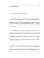
There are three types of RFID tag which is passive tag, active tag and semi
passive tag. Passive tag refers to RFID tag which is powered solely by the RFID
reader. The reader emits a radio frequency (RF), which powers the silicon chip on
the tag when it is within range of the RF signal. When the power to the silicon chip
8
on the tag meets the minimum voltage threshold it require to turn on, the silicon chip
can then send back information on the same RF wave. Range is usually limited to
several meters.
Active tag refer to RFID tags which have their own power source, so they
can receive a weaker signal from the reader, and the power source on the tag boosts
the return signal. These types can have ranges of many tens of meters and even
hundreds of meters, but will cost more because of their size and sophistication.
Battery life can also limit the life of the tag. Meanwhile, semi passive tag refer to
tag with a power source (usually a laminar, flexible, low cost battery) which can be
used for tag sensing, but not to boost range. Figure 2.1 shows the example of RFID
tags.
Figure 2.1 The example of RFID tags
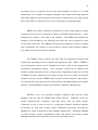
2.2.3
The RFID Reader
RFID reader is use to extract data from RFID tag. It consists of radio
circuitry (RFID Antenna) for generation and detection of radio waves,
computational device for basic processing and filtering of signals such as the
microcontroller.
The radio circuitry section includes an RF carrier generator,
antenna and a tuning circuit. The antenna and its tuning circuit must be properly
9
designed and tuned for the best performance. Figure 2.2 shows the example of
RFID reader.
Figure 2.2 The example of RFID reader
2.2.4
The RFID Frequency
Frequency refers to the size of the radio waves used to communicate between
the RFID systems components. Just as tuning the radio to different frequencies in
order to hear different radio stations, RFID tag and reader have to be tuned to the
same frequency in order to communicate effectively. RFID systems typically use
one of the following frequency ranges: low frequency (or LF, around 170 kHz), high
frequency (or HF, around 13.56 MHz), ultra-high frequency (or UHF, around 868
and 928 MHz), or microwave (around 2.45 and 5.8 GHz). It is generally safe to
assume that a higher frequency equates to a faster data transfer rate and longer read
ranges, but also more sensitivity to environmental factors such as liquid and metal
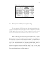
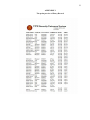
that can interfere with radio waves. Table 2.1 shows some example of the frequency
range and read range between the tag and the reader.
10
Table 2.1 The read range between the reader and tag
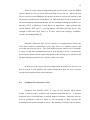
2.2.5
Basic Operation of RFID Systems using Passive Tag
The basic operation of RFID system starts when tag is energized by a timevarying electromagnetic radio frequency (RF) wave that is transmitted by the reader.
This RF signal is called a carrier signal. The tag is composed of an antenna coil and
a silicon chip that includes basic modulation circuitry and non-volatile memory.
When the RF field passes through an antenna coil, there is an AC voltage
generated across the coil. This voltage is rectified to result in a DC voltage for the
device operation. The device becomes functional when the DC voltage reaches a
certain level. The information stored in the device is transmitted back to the reader.
This is often called backscattering. By detecting the backscattering signal, the
information stored in the device can be fully identified by the reader. Because the
passive tag is remotely powered by reader’s RF signal, it deals with very small
power (~ μw). Thus, the read range (communication distance between reader and
tag) is typically limited within a proximity distance [1].
11
Data decoding for the received signal is accomplished using a
microcontroller in the reader. The firmware algorithm in the microcontroller is
written in such a way to transmit the RF signal, decode the incoming data and
communicate with the host computer. Figure 2.3 shows the basic operation of RFID
system.
Figure 2.3 Basic Operation of RFID System
2.2.6
The applications of RFID
Nowadays, RFID is being used widely in many applications such as transport
payment, product tracking, automotive, animal identification, human implants and
also in libraries.
Moreover, high frequency RFID tags are used in library book or bookstore
tracking, pallet tracking, building access control, airline baggage tracking, and
apparel and pharmaceutical items tracking. High-frequency tags are widely used in
identification badges, replacing earlier magnetic stripe cards. These badges need
12
only be held within a certain distance of the reader to authenticate the holder. The
American Express Blue credit card now includes a high-frequency RFID tag.
The uniqueness of RFID tags means that a product may be individually
tracked as it moves from location to location, finally ending up in the consumer's
hands. This may help companies to combat theft and other forms of product loss. It
has also been proposed to use RFID for point-of-sale store checkout to replace the
cashier with an automatic system which needs no barcode scanning.
2.2.7
The advantages of RFID
There are many potential used of RFID such as RFID tag are often
envisioned as a replacement for bar-codes, having a number of important advantages
over the older bar-code technology. RFID codes are long enough that every RFID
tag may have a unique code, while current barcodes are limited to a single code for
all instances of a particular product.
Another significant advantage of all types of RFID systems is the non
contact, non-line-of-sight nature of the technology. Tags can be read through a
variety of substances such as snow, fog, ice, paint, crusted grime, and other visually
and environmentally challenging conditions, where barcodes or other optically read
technologies would be useless.
RFID tag can also be read in challenging circumstances at remarkable
speeds, in most cases responding in less than 100 milliseconds. The read and write
capability of an active RFID system is also a significant advantage in interactive
applications such as work-in-process or maintenance tracking.
Though it is a
costlier technology (compared with barcode), RFID has become indispensable for a
13
wide range of automated data collection and identification applications that would
not be possible otherwise.
2.3
Database Management System (DBMS)
A database management system (DBMS) is computer software designed for
the purpose of managing databases based on a variety of data models. DBMS is a
complex set of software programs that controls the organization, storage,
management, and retrieval of data in a database. DBMS are categorized according
to their data structures or types, some time DBMS is also know as Data base
Manager. It is a set of prewritten programs that are used to store, update and
retrieve a database.
A DBMS includes a modeling language to define the schema of each
database hosted in the DBMS, according to the DBMS data model. The four most
common types of organizations are the hierarchical, network, relational and object
models.
Inverted lists and other methods are also used.
A given database
management system may provide one or more of the four models. The optimal
structure depends on the natural organization of the application's data, and on the
application's requirements which include transaction rate (speed), reliability,
maintainability, scalability, and cost.
DBMS also includes data structures (fields, records, files and objects)
optimized to deal with very large amounts of data stored on a permanent data
storage device, a database query language and report writer to allow users to
interactively interrogate the database, analyze its data and update it according to the
user’s privileges on data. It is also controls the security of the database. Data
security prevents unauthorized users from viewing or updating the database. Using
14
passwords, users are allowed access to the entire database or subsets of it called
subschemas. For example, an employee database can contain all the data about an
individual employee, but one group of users may be authorized to view only payroll
data, while others are allowed access to only work history and medical data.
DBMS also allows transaction mechanism to ensure data integrity, despite
concurrent user accesses (concurrency control), and faults (fault tolerance). It also
maintains the integrity of the data in the database. The DBMS can maintain the
integrity of the database by not allowing more than one user to update the same
record at the same time. The DBMS can help prevent duplicate records via unique
index constraints; for example, no two customers with the same customer numbers
(key fields) can be entered into the database.
The DBMS accepts requests for data from the application program and
instructs the operating system to transfer the appropriate data. When a DBMS is
used, information systems can be changed much more easily as the organization's
information requirements change. New categories of data can be added to the
database without disruption to the existing system. Organizations may use one kind
of DBMS for daily transaction processing and then move the detail onto another
computer that uses another DBMS better suited for random inquiries and analysis.
Overall systems design decisions are performed by data administrators and systems
analysts. Detailed database design is performed by database administrators.
Database servers are specially designed computers that hold the actual
databases and run only the DBMS and related software.
Database servers are
usually multiprocessor computers, with disk arrays used for stable storage.
Connected to one or more servers via a high-speed channel, hardware database
accelerators are also used in large volume transaction processing environments.
DBMSs are found at the heart of most database applications. Sometimes DBMSs
are built around a private multitasking kernel with built-in networking support
although nowadays these functions are left to the operating system.
15
There are many software programming that can be used to create the DBMS
such as Microsoft Access, Oracle, Microsoft SQL Server and etc. Microsoft SQL
Server is used to create DBMS for this project because its can provide data layer and
can interact with Microsoft Visual Basic 6.0. Microsoft SQL Server is used to store
all the information needed and the data will be manipulated using the Graphic User
Interface (GUI) in Microsoft Visual Basic 6.0 application. Other products like
Visual Studio® .NET and C++ can also interact with Microsoft SQL Server. The
strength of Microsoft SQL Server is its more robust data integrity, scalability,
security, and manageability [2].
Basically, Microsoft SQL Server client/server communication works start
with client software communicates with SQL Server by sending requests and
receiving data from the server. The client makes requests, and the server responds.
It turns out that this communication has to pass through a series of connectivity
layers on the client, from the application down to the network level, and then back
up again through a parallel series of layers on the server side.
In the process, the request must be wrapped with instructions to the server on
how to decode it, and similarly the results coming back from the server must be
decoded and unpacked on the client machines.
2.4
Graphical User Interface (GUI)
Graphical User Interface (GUI) is a type of user interface which allows
people to interact with a computer and computer-controlled devices. It presents
graphical icons, visual indicators or special graphical elements. Often the icons are
used in conjunction with text, labels or text navigation to fully represent the
information and actions available to a user. But instead of offering only text menus,
16
or requiring typed commands, the actions are usually performed through direct
manipulation of the graphical elements [3].
The term GUI is historically restricted to the scope of two-dimensional
display screens with display resolutions capable of describing generic information,
in the tradition of the computer science research at Palo Alto Research Center
(PARC) (formerly Xerox PARC and still a subsidiary of Xerox). The term GUI
might not apply to other high-resolution types of interfaces that are non-generic,
such as videogames, or not restricted to flat screens, like volumetric displays. The
precursor to GUIs was invented by researchers at the Stanford Research Institute, led
by Douglas Engelbart. They developed the use of text-based hyperlinks manipulated
with a mouse for the On-Line System. The concept of hyperlinks was further
refined and extended to graphics by researchers at Xerox PARC, who went beyond
text-based hyperlinks and used a GUI as the primary interface for the Xerox Alto
computer. Most modern general-purpose GUIs are derived from this system.
Designing the visual composition and temporal behavior of GUI is an
important part of software application programming. Its goal is to enhance the
efficiency and ease of use for the underlying logical design of a stored program, a
design discipline known as usability. Techniques of user-centered design are used to
ensure that the visual language introduced in the design is well tailored to the tasks it
must perform.
Typically, the user interacts with information by manipulating visual widgets
that allow for interactions appropriate to the kind of data they hold. The widgets of
a well-designed interface are selected to support the actions necessary to achieve the
goals of the user. A Model-view-controller allows for a flexible structure in which
the interface is independent from and indirectly linked to application functionality,
so the GUI can be easily customized. This allows the user to select or design a
different skin at will, and eases the designer's work to change the interface as the
user needs evolve. Nevertheless, good user interface design relates to the user, not
17
the system architecture. The visible graphical interface features of an application are
sometimes referred to as chrome. Larger widgets, such as windows, usually provide
a frame or container for the main presentation content such as a web page, email
message or drawing. Smaller ones usually act as a user-input tool.
A GUI may be designed for many requirements of a vertical market. This is
known as an application specific graphical user interface. The examples of GUI
applications are touch screen point of sale software used by wait staff in a busy
restaurant, self-service checkouts used in a retail store, automated teller machines
(ATM), airline self-ticketing and check-in, information kiosks in a public space like
a train station or a museum and monitors or control screens in an embedded
industrial application which employ a real time operating system. The latest cell
phones and handheld game systems also employ application specific touch screen
GUIs.
Microsoft Visual Basic 6.0 was designed to be easy to learn and use. The
language not only allows programmers to create simple GUI applications, but can
also develop complex applications as well. Programming in Microsoft Visual Basic
6.0 is a combination of visually arranging components or controls on a form,
specifying attributes and actions of those components, and writing additional lines of
code for more functionality. Since default attributes and actions are defined for the
components, a simple program can be created without the programmer having to
write many lines of code. Performance problems were experienced by earlier
versions, but with faster computers and native code compilation this has become less
of an issue.
Microsoft Visual Basic 6.0 is designed to allow the program run under the
windows without the complexity generally associated with windows programming.
The designed screen can holds standard windows button such as command buttons,
check boxes, option buttons, text boxes, and so on. Each of these windows object,
operates as expected, producing a “standard” windows user interface. Microsoft
18
Visual Basic 6.0 that recently appears as one of the most popular programming
language is chose. It provided standard windows object and graphic user interface
that will make the program become user friendly.
Since Microsoft Visual Basic 6.0 is a high-level programming and have been
designed to make it easy to create GUI applications, this project will used Microsoft
Visual Basic 6.0 to create the GUI. More than that, Microsoft Visual Basic 6.0
applications can be integrated with the database and interact with hardware. As the
world turn to GUI application, Microsoft Visual Basic 6.0 is one of the languages
that changes to accommodate the shift.
CHAPTER 3
METHODOLOGY
3.1
Introduction
This chapter describes the methodology that is use in developing the project.
The development involves three stages which is hardware development, software
development and interfacing of both hardware and software.
3.2
Hardware Development
For the hardware development, the RFID system which consists of tag and
reader was adjusted so that it can function according to the proposed application.
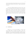
The tag used in this project is passive tag and operates at frequency of 125 KHz.
The passive tag is chosen for this project because it does not need power source as it
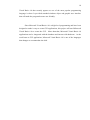
is energized by the reader. More over it is cheap which only cost RM 3 per tag. The
tag was stored with a unique code that identifies each user. There are many types of
RFID tags which include card and key chain as shown in Figure 3.1. For this
20
project, the card tag is used because is it more suitable and easy to carry at anytime
and anywhere. The card tag can be used as a smart card during entering UTM as
shows in Figure 3.2.
Figure 3.1 The key chain and card type of RFID tags
Figure 3.2 The RFID Smart Card for the project
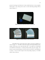
This RFID reader is used in this project which is also known as IDR-232 as
shown in Figure 3.3. The IDR-232 has been designed with integrated RFID reader,
antenna, LED, buzzer, power cable and data cable. It uses data rate of 9600 baud
rate and RS232 serial interface. It is fully operation with 5V DC power supply. The
buzzer is used as sound indication of activity and bi-color LED for visual indication
of activity. It has 0.1second response time and operating frequency of 125 KHz
which is same as the tag.
21
Figure 3.3 The RFID reader
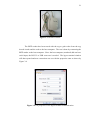
The RFID reader has been tested with the tag to grab codes from the tag,
decode it and send the code to the host computer. The test is done by connecting the
RFID reader to the host computer. Since the host computer (notebook) did not have
serial input, the RS 232 to USB converter is needed. The hyper terminal window
will then opened and new connection was set with the properties same as shows by
Figure 3.4.
Figure 3.4 The properties of the hyper terminal communication
22
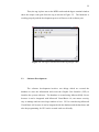
Then, the tag is place near to the RFID reader and the hyper terminal window
show the unique code grab from the tag as shown in Figure 3.5. The hardware is
working properly and the development process will move to the software part.
Figure 3.5 The hyper terminal shows the tag unique code
3.3
Software Development
The software development involves two things which are created the
database to store the information and create the Graphic User Interface (GUI) to
interface the system with user. The database is created using Microsoft SQL Server
because it can be integrated with Microsoft Visual Basic 6.0, can ensure security,
easy to manage and can store large number of user. GUI is created using Microsoft
Visual Basic 6.0 because it can be integrated with the database and the hardware and
also the programming for GUI can be created such user friendly.
23
3.3.1
Database
The database of this project stored all the information about the user of the
system and the record of incoming traffic at the entrance. The database with server
name of FAZLINA-663E7EB is created using Microsoft SQL Server and the
connection properties is set as shows in Figure 3.6.
Figure 3.6 The connection properties of the database
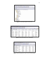
Then, after connect the server of the database, the database name as
StdEntrance is created to store all information needed for the system. The new table
that store all the information can be created by right click at the tables at the object
explorer and choose add new table. The object explorer of the server is shows in
Figure 3.7. There are two tables created for this system. One of the tables is used to
store information of the user includes the unique code, user name, UTM ID, user
position, vehicle registration number, vehicle colour, vehicle type and vehicle
manufacturer as shown in Figure 3.8. Another table is used to store the entry record
of the UTM entrance include user name, UTM ID, user position, vehicle registration
number, date and time as shown in Figure 3.9.
24
Figure 3.7 The object explorer of the server
Figure 3.8 The table that store user information
Figure 3.9 The table that store entry record of UTM entrance
25
3.3.2
Graphic User Interface (GUI)
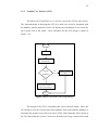
The Microsoft Visual Basic 6.0 is used to create the GUI for this project.
The important thing in designing the GUI is to make sure it can be integrated with
the database and the hardware, hence can display the information of user when the
tag is place near to the reader. Basic flowchart for the GUI design is shows in
Figure 3.10.
Start
Read Tag
Compare Tag ID
with Database
Tag ID
=
Database
No
Display “Invalid
ID”
Yes
Display Car
Registration Number
and User Information
End
Figure 3.10 The flowchart of the programming
The design of the GUI is simulated until it gives desired output. Then, the
GUI design to store the record entry in the database also created and the database is
automatically updated every time user enters UTM. More than that, other option in
the GUI that make the system is more user friendly also being created such as add
26
new user, delete user, view database, help, request for user manual and also print the
record entry.
3.4
Interface
Figure 3.11 The connection of the system
The hardware and software is interface at the end of the project. Figure 3.11
shows the connection of the system from the reader to the host computer. A serial
communication (RS-232) is used to connect the host computer to the RFID reader.
Because of the host computer (notebook) didn’t have the serial input, so the RS 232
to USB converter is used to connect the reader to the host computer. The reader also
27
connected to another one of the USB port to get the power supply. The project is
successful and had given desired output. The results will be discussed in Chapter 4.
CHAPTER 4
RESULT
4.1
Introduction
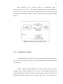
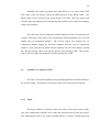
This chapter describes the result after completing the project. Generally, the
reader successful energized and grabs the unique code from the tags and then sent
the unique code to the host computer. The host computer successful receives the
unique code and compare with the database. The created GUI successful displays
user information if the tag valid and displays “Invalid ID” if the tag is not valid. The
block diagram of the UTM Security Entrance System is illustrated in Figure 4.1.
Figure 4.1 The block diagram of the project
29
Basically, the system operation start when there is a car enters into UTM.
The owner of the car needs to place the RFID tag near to the RFID reader. The
RFID reader will be located at the main entrance of UTM. Then, the reader will
energized the tag and grab code from the tag and send the code to the host computer
using serial interface.
The code then will be compared with the database by the GUI that has been
created. After that, if the code of the card matched with the database, the GUI will
display the car registration number.
The security officer can compare the car
registration number display by the host computer and the real car registration
number. If the card did not match with the database, the GUI will display ‘Invalid
ID’ and the security officer can stop the person from entering UTM. The security
officer will only allow the authorized vehicle entering into UTM.
4.2
Graphic User Interface (GUI)
The GUI is created according to the proposed application and successful give
the desired output. The details of each parts of the GUI will be discussed below.
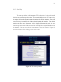
4.2.1
Login
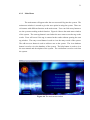
The login window is created to ensure the safety of the system and to make
sure only administrator that have user name and password can log into the system.
The administrator need to key in the username which is “nazuria” and the password
30
which is “kecik” and click login to log into the system. Figure 4.2 shows the login
window of the system.
Figure 4.2 The login window
If the user key in invalid username and password, the message box that
inform invalid login will appear as shows in Figure 4.3. User is supposed to enter
the correct user name and password to log in into the system.
Figure 4.3 The invalid login message box
31
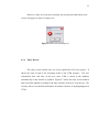
4.2.2
Main Menu
The main menu will appear after the user successful log into the system. The
main menu window is created to give the user option in using the system. There are
six buttons with different function at the main menu. User can click at any button to
use the system according to their function. Figure 4.4 shows the main menu window
of the system. The scan tag button is used when the user want to scan the tag on the
reader. Error will occur if the tag is scanned at the reader without opening the scan
tag window. The entry record button is used to view the entry record of the system.
The add new user button is used to add new user to the system. The view database
button is used to view the database of the system. The help button is used to view
the user manual and description of the system. The exit button is used to exit from
the system.
Figure 4.4 The main menu window
32
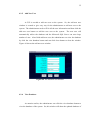
4.2.3
Scan Tag
The scan tag window is the important GUI in the project. It shows the result
after the user scan the tag at the reader. The essential things are the GUI can receive
the unique id from the tag and compare the unique id with the database. Error will
occur if the tag is scanned at the reader without opening this window. The vehicle
number and others user information will be displayed automatically after the user
scan the tag at the reader if the user used the valid tag that is registered and store in
the database. The user can click the close button to close the window. Figure 4.5
shows the window if the valid tag is scan at the reader.
Figure 4.5 The scan tag window
33
However, if the user scan the invalid tag, the message box that inform error
occurs will appear as shows in Figure 4.6.
Figure 4.6 The error message box
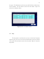
4.2.4
Entry Record
The entry record window also one of the significant GUI in the project. It
shows the entry record of the incoming traffic at the UTM entrance. The user
information, date and time of the user enter UTM is stored in the database
automatically as this window is updated. Figure 4.7 shows the entry record window
that successful updated according to the date and time of the user scan the tag. The
security officer can used this information for further reference if anything happens in
UTM.
34
Figure 4.7 The entry record window
More than that, there is also a print preview button that can be use by the
security officer to see the print preview of the entry record and also print button to
print out the entry record. The example of the print preview is shows in Figure 4.8.
The close button is used to close the window.
Figure 4.8 The example of the print preview
35
4.2.5
Add New User
A GUI is needed to add new user to the system. So, the add new user
window is created to give easy way for the administrator to add new user to the
system. The administrator need to fill in all the user information and then click the
add new user button to add the new user to the system.
The new user will
automatically add to the database and the Microsoft SQL Server can store large
number of user. After finish add new user, the administrator can view the database
by click the view database button and can click close button to close the window.
Figure 4.9 shows the add new user window.
Figure 4.9 The add new user window
4.2.6
View Database
As mention earlier, the administrator can click the view database button to
view the database of the system. So, this window will show the updated database of
36
the system. The administrator can select any user and click delete to delete the user
from the database. The close button is used to close this window. Figure 4.10
shows the view database window.
Figure 4.10 The view database window
4.2.7
Help
The help window is used when the user want to read the brief description
about the system. The user also can click user manual button to get the user manual
of the system. The close button is used to close the window. Figure 4.11 shows the
help window.
37
Figure 4.11 The help window
CHAPTER 5
DISCUSSIONS AND CONCLUSIONS
5.1
Introduction
This chapter describes the discussions and conclusions of the UTM Security
Entrance using RFID project.
In addition, some recommendations for further
development is also included in this chapter.
5.2
Discussions and Conclusions
The development of the project had been done smoothly according to the
planning until it is completed. Although there are some difficulties at the beginning
of the development process such as, a beginner in both of the programming language
used in this project, the project however managed to be completed and the desired
result had been obtained.
39
The RFID system which includes the tag and reader had successful function
according to the proposed application. The reader is able to grab the unique id from
the tag that indicates every user of the system. The host computer also successful
interfaces with the RFID system and can receive the unique id from the reader. The
GUI programming successful communicates with both, the database and the RFID
system. The GUI programming able to compare the unique id with the database and
displays appropriate information. More than that, the GUI programming also can
automatic record the information into the database every time user enters into UTM.
After completing this project, the objective of this project which is to
develop an easy and efficient system for Security Department to monitor and record
the car entry into UTM and also to reduce the time taken by staff and students
during entering UTM had been achieved. This project had developed a system that
is easy and efficient to monitor the UTM entrance which is simply by the user touch
the tag to the reader compare to using manual system that have been mention earlier.
The time taken by user to touch the tag is less than the time taken by the security
officer to look and check the car number display at the car sticker. Hence, this will
definitely reduce the time taken by staff and student during entering UTM.
In conclusion, the UTM Security Entrance using RFID System will not just
omit the bottle neck at the entrance but also make a better record of UTM security
system for the UTM Security Department.
5.3
Future Development
Some further work can be done to improve this project in the future such as
place the RFID tag at the car sicker and also add the LCD displays as output of the
system. The RFID tag can be place at the car sticker, but the system need an
40
external antenna to read the tag and must use higher frequency for the long range
between the tag and the external antenna. Meanwhile, the LCD display need some
circuit and controller and must be interface to the system using Visual Basic (GUI).
Instead of using passive RFID tag, active RFID tag is a good alternative to
produce better security system that will ease the entering vehicle. They would not
have to stop and touch the reader but can just pass by the reader. This is because
active RFID tag can be read in farther distance than passive RFID tag.
41
REFERENCES
[1] Microchip, microID® 13.56 MHz RFID System Design Guide, Microchip
[2] Paul Nielsen, SQL Server 2005 Bible, Wiley Publishing, Inc, 2007
[3] Brian Siler and Jeff Spotts, Special Edition using Visual Basic 6, PrenticeHall of India, New Delhi, 2002
[4] John Carter, Database Design and Programming with Access, SQL and Visual
Basic, University of East London, McGraw Hill, England, 2000
[5] Mohd. Shahizan Othman, Suraya Miskon, Syed Norris Hikmi Syed Abdullah,
Norasnita Ahmad, and Roliana Ibrahim, Microsoft SQL Server 2000, UTM,
Skudai, 2004
42
APPENDIX A
Programming for Login
Private Sub cmdLogin_Click()
If txtusername.Text = "" Then
MsgBox "Please enter the USERNAME!!!", 0 + 48, "Error"
Exit Sub
End If
If txtpassword.Text = "" Then
MsgBox "Please enter the PASSWORD!!!", 0 + 48, "Error"
Exit Sub
End If
If txtusername.Text = "nazuria" Then
If txtpassword.Text = "kecik" Then
Unload Me
Call Loading.Show
Else
txtusername.Text = ""
txtpassword.Text = ""
MsgBox "Please Try Again", 0 + 48, "Invalid Login"
Login.Show
End If
End If
End Sub
Private Sub Form_Load()
End Sub
Private Sub Timer1_Timer()
Label8.Caption = Format(Date, "DD/MM/YY")
End Sub
Private Sub Timer2_Timer()
Label9.Caption = Format(Time, "HH:MM:SS")
End Sub
43
APPENDIX B
Programming for Loading
Private Declare Sub Sleep Lib "kernel32" (ByVal dwMilliseconds As Long)
Private Sub Form_Load()
Timer1.Enabled = True
End Sub
Sub Progress(pb As Control, ByVal Percent)
Dim num$
If Not pb.AutoRedraw Then
pb.AutoRedraw = -1
End If
pb.Cls
pb.ScaleWidth = 100
pb.DrawMode = 10
num$ = Format$(Percent, "###") + "%"
pb.CurrentX = 50 - pb.TextWidth(num$) / 2
pb.CurrentY = (pb.ScaleHeight - pb.TextHeight(num$)) / 2
pb.Print num$
pb.Line (0, 0)-(Percent, pb.ScaleHeight), , BF
pb.Refresh
End Sub
Private Sub lblMainMenu_Click()
End Sub
Private Sub Timer1_Timer()
Picture1.ForeColor = vbBlue
For X% = 0 To 100
Sleep 50
Progress Picture1, X%
Next X%
Timer1.Enabled = False
Unload Me
Mainmenu.Show
End Sub
44
APPENDIX C
Programming for Main Menu
Option Explicit
Private Sub cmdeditdatabase_Click()
Call editdatabase.Show
End Sub
Private Sub cmdexit_Click()
End
End Sub
Private Sub cmdhelp_Click()
Call help.Show
End Sub
Private Sub cmdreport_Click()
Call report.Show
End Sub
Private Sub cmdrfidreader_Click()
Call rfidreader.Show
End Sub
Private Sub cmdview_Click()
Call view.Show
End Sub
Private Sub Command1_Click()
database.Show
End Sub
Private Sub Label1_Click()
45
End Sub
Private Sub mnueditdatabase_Click()
editdatabase.Show
End Sub
Private Sub mnuexit_Click()
End
End Sub
Private Sub mnuhelp_Click()
help.Show
End Sub
Private Sub mnurfidreader_Click()
rfidreader.Show
End Sub
Private Sub mnuview_Click()
view.Show
End Sub
Private Sub Timer1_Timer()
Label8.Caption = Format(Date, "DD/MM/YY")
End Sub
Private Sub Timer2_Timer()
Label9.Caption = Format(Time, "HH:MM:SS")
End Sub
Private Sub Timer3_Timer()
Label1.Visible = Not Label1.Visible
End Sub
46
APPENDIX D
Programming for Scan Tag
Const portnum As Integer = 5
Public Aline As String
Public flagIn As Boolean
Private Sub cmdback_Click()
Unload Me
Call Mainmenu.Show
End Sub
Private Sub Form_Load()
Dim vntBookmark As Variant
flagIn = False
With MSComm1
If .PortOpen = False Then
.CommPort = 5
.Settings = "9600,n,8,1"
.RThreshold = 1
.RTSEnable = True
.InputLen = 1
.PortOpen = True
End If
End With
Form_load_exit:
Exit Sub
err_exit:
MsgBox "Unable to Open Comm Port", vbCritical, "CommPort Error"
End Sub
Private Sub MSComm1_OnComm()
Dim Achar As String
Achar = MSComm1.Input
Aline = Aline & Achar
txtTag.Text = Aline
If Len(Aline) = 10 Then
47
With AdoRecord.Recordset
vntBookmark = .Bookmark
.MoveFirst
.Find "Code Like " & Aline & ""
End With
If AdoRecord.Recordset.EOF Then
MsgBox "Invalid ID!!!", vbCritical, "Error"
AdoRecord.Recordset.Bookmark = vntBookmark
End If
If Text1.Text = "" Then
AdoEntrance.Recordset.AddNew
AdoEntrance.Recordset.Fields("User Name") = Text2.Text
AdoEntrance.Recordset.Fields("UTM ID") = Text3.Text
AdoEntrance.Recordset.Fields("User Position") = Text4.Text
AdoEntrance.Recordset.Fields("Vehicle No") = Text8.Text
AdoEntrance.Recordset.Fields("Date") = label10(0).Caption
AdoEntrance.Recordset.Fields("Time") = Label9.Caption
AdoEntrance.Recordset.Update
End If
Aline = ""
End If
End Sub
Private Sub Form_UnLoad(Cancel As Integer)
If MSComm1.PortOpen = True Then
MSComm1.PortOpen = False
End If
End Sub
Private Sub Timer1_Timer()
label10(0).Caption = Format(Date, "DD/MM/YY")
End Sub
Private Sub Timer2_Timer()
Label9.Caption = Format(Time, "HH:MM:SS")
End Sub
48
APPENDIX E
Programming for Entry Record
Option Explicit
Private Sub cmdback_Click()
Unload Me
Call Mainmenu.Show
End Sub
Private Sub Command1_Click()
rptEntrance.PrintReport
End Sub
Private Sub Command2_Click()
Adodc1.Recordset.Update
rptEntrance.Show
End Sub
Private Sub Form_Load()
End Sub
49
APPENDIX F
Programming for Add New User
Option Explicit
Private Sub cmdback_Click()
Unload Me
Call Mainmenu.Show
End Sub
Private Sub VScroll1_Change()
End Sub
Private Sub Command1_Click()
If Text1.Text = "" Then
MsgBox "Please enter the USERNAME!!!", 0 + 48, "Error"
Exit Sub
End If
If Text2.Text = "" Then
MsgBox "Please enter the RFID Code!!!", 0 + 48, "Error"
Exit Sub
End If
If Text3.Text = "" Then
MsgBox "Please enter the UTM ID!!!", 0 + 48, "Error"
Exit Sub
End If
If Text4.Text = "" Then
MsgBox "Please enter the Vehicle No!!!", 0 + 48, "Error"
Exit Sub
End If
If Text5.Text = "" Then
MsgBox "Please enter the Vehicle Colour!!!", 0 + 48, "Error"
Exit Sub
End If
50
If Text7.Text = "" Then
MsgBox "Please enter the Vehicle Manufacturer!!!", 0 + 48, "Error"
Exit Sub
End If
Adodc1.Recordset.AddNew
Adodc1.Recordset.Fields("User Name") = Text1.Text
Adodc1.Recordset.Fields("Code") = Text2.Text
Adodc1.Recordset.Fields("UTM ID") = Text3.Text
Adodc1.Recordset.Fields("User Position") = Combo1.Text
Adodc1.Recordset.Fields("Vehicle No") = Text4.Text
Adodc1.Recordset.Fields("Vehicle Colour") = Text5.Text
Adodc1.Recordset.Fields("Vehicle Type") = Combo2.Text
Adodc1.Recordset.Fields("Vehicle Manufacturer") = Text7.Text
MsgBox "Successful add new user to the system!!!", vbExclamation, "Thank
You"
End Sub
Private Sub Command3_Click()
Unload Me
database.Show
End Sub
Private Sub Form_Load()
End Sub
51
APPENDIX G
Programming for View Database
Option Explicit
Private Sub Command1_Click()
Unload Me
Call Mainmenu.Show
End Sub
Private Sub Command2_Click()
Adodc1.Recordset.Delete
If Not Adodc1.Recordset.EOF Then
Adodc1.Recordset.MovePrevious
End If
End Sub
Private Sub DataGrid1_Click()
End Sub
52
APPENDIX H
Programming for Help
Option Explicit
Private Sub cmdback_Click()
Unload Me
Call Mainmenu.Show
End Sub
Private Sub Command1_Click()
Call getpdf(App.Path & "\user manual.pdf", Me.hwnd)
End Sub
Private Sub Label1_Click()
End Sub
53
APPENDIX I
The print preview of Entry Record