1
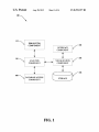
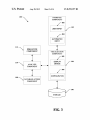
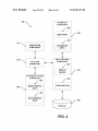
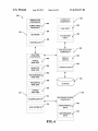
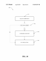
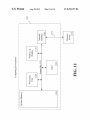
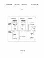
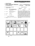
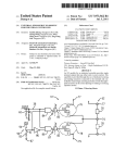
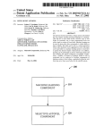
US008255197B2
(12) United States Patent
(10) Patent N0.:
(45) Date of Patent:
Pritchard et a].
(54)
SIMULATION OF TUNING EFFECTS FOR A
SERVO DRIVEN MECHATRONIC SYSTEM
(56)
US 8,255,197 B2
Aug. 28,2012
References Cited
U.S. PATENT DOCUMENTS
(75) Inventors: John Pritchard, Cedarburg, WI (US);
Mark A. Chaffee, Chagrin Falls, OH
(US); Graham Elvis, Norton Canes
(GB)
(73) Assignee: Rockwell Automation Technologies,
Inc., May?eld Heights, OH (US)
(*)
Notice:
7,868,610 B2 *
2002/0111758 A1 *
l/20ll
8/2002
2004/0030461 A1 *
2/2004 Flores et a1.
2004/0049368 A1 *
3/2004
Hamm et a1. ..
2004/0144177 A1 *
7/2004
Flock et a1. ...... ..
2006/0048015 A1 *
3/2006 Bardelang et a1. .
2006/0184280 A1 *
8/2006 Oddsson et a1.
2007/0067678
A1 *
2007/0283188 A1 *
Subject to any disclaimer, the term of this
patent is extended or adjusted under 35
U.S.C. 154(b) by 693 days.
Velinsky et a1. ....... .. 324/20725
Wang et a1.
....... .. 702/79
2008/0033897
3/2007
Hosek et a1.
701/1
.......
703/2
73/660
714/45
700/245
. . . ..
12/2007 BalZer et a1.
... ... ... ...
714/25
714/26
A1 *
2/2008
Lloyd
2008/0039959 A1 *
2/2008
Fister et a1. ................... .. 700/56
. . . ..
706/19
* cited by examiner
Primary Examiner * Kandasamy Thangavelu
(21) Appl. N0.: 12/242,403
(74) Attorney, Agent, or Firm *Turocy & Watson, LLP;
Raymond Speroff
(22) Filed:
Sep. 30, 2008
(57)
(65)
Prior Publication Data
US 2010/0082314 A1
ABSTRACT
A servo driven mechatronic system simulator and analyzer
utilizing precon?gured motion equipment pro?le databases
Apr. 1, 2010
to predict the behavior of a motion system based on a user
selected con?guration. The user can adjust the parameters
and rerun the simulation and analysis many times in an e?i
(51)
Int. Cl.
(52)
(58)
US. Cl. ........................... .. 703/13; 700/245; 714/25
desired system are reached. The user can then archive the
Field of Classi?cation Search .............. .. 703/7, 13,
system design and implement the system With a greater level
of con?dence in the ability of the design to meet the require
ments of the application.
G06F 17/50
(2006.01)
cient manner until the optimum operating conditions of the
703/2, 6; 700/56, 245; 706/19; 714/25,
714/26, 45; 702/79; 701/11; 324/207.25;
73/660
See application ?le for complete search history.
20 Claims, 14 Drawing Sheets
100 \
112 -\
SIMULATION
COMPONENT
A
INTERFACE
COIVIPONENT
/ 102
11
V
110
\
ANALYSIS
COMPONENT
Y
VISUALIZATION
COIVIPONENT
/ 104
1
V
V
108
_\ DATABASE ACCESS
COMPONENT
106
US. Patent
Aug. 28, 2012
Sheet 1 0114
US 8,255,197 B2
100 \
112
\
SIMULATION
COMPONENT
102
INTERFACE
COMPONENT
110 \
I
ANALYSIS
COMPONENT
VISUALIZATION
COMPONENT
104
106
\ DATABASE ACCESS
COMPONENT
FIG. 1
US. Patent
Aug. 28, 2012
US 8,255,197 B2
Sheet 2 0f 14
100 \
INTERFACE
COIVIPONENT
/ 202
/— 102
USER INPUT
112 -\
/— 204
SIMULATION
AUTOMATED
COMPONENT
INPUT
110
\
I
ANALYSIS
COMPONENT
I
1 04
VTSUALIZATION
COMPONENT I/
106
108 \
DATABASE ACCESS
COMPONENT
FIG. 2
US. Patent
Aug. 28, 2012
100
Sheet 3 0114
US 8,255,197 B2
INTERFACE
COMPONENT
/ 202
_
USER INPUT
102
/
/—204
AUTOMATED
INPUT
112
\
SIMULATION
COMPONENT
VISUALIZATION
COMPONENT
/- 302
110
\
ANALYSIS
DISPLAY
DEVICE
/ 104
COMPONENT
/ 304
CONFIGURATION
10s
\ DATABASE ACCEss
COMPONENT
106
FIG. 3
US. Patent
Aug. 28, 2012
Sheet 4 0f 14
US 8,255,197 B2
INTERFACE
100 \
COMPONENT
/- 202
USER INPUT
/_
102
204
112
f
\
110
\
SIMULATION
AUTOMATED
COMPONENT
|NPUT
ANALYSIS
VISUALIZATION
COMPONENT
COMPONENT
/_ 302
DISPLAY
DEVICE
DATABASE ACCESS
COMPONENT
f 402
108
\
MOVE PROF||_E
DATA
/
104
304
/
CONFIGURATION
/- 404
MOTOR/DRIVE
DATA
106
FIG. 4
US. Patent
Aug. 28, 2012
Sheet 5 0f 14
US 8,255,197 B2
INTERFACE
100 \
/
COMPONENT
102
/- 202
USER INPUT
/
/_ 204
SIMULATION
AuTlgg’aTED /
COMPONENT
104
ANALYSIS
VISUALIZATION /
COMPONENT
COMPONENT
<—>
FORCE
ANALYSIS
'\— 502
AXIS STOP
ANALYSIS
'\~ 504
/- s02
DISPLAY
DEVICE
,/
/_ 304
/
CONFIGURATION
RATIO/DESIGN 5
ANALYSIS
‘\~ 506
TOLERANCE
I
I
ANALYSIS '\— 50s
TORQUE
110
\
ANALYSIS
‘\— 510
108
DATABASE ACCESS
POWER SUPPLY '\— 512
COMPONENT
/- 402
<——>
LIFE ESTIMATE .\_ 514
MOVE PROFILE /
DATA
/- 404
MECHANICAL
LIMITATIONS
MOTOR/DRIVE /
‘\~ 516
FIG. 5
DATA
106
US. Patent
100
Aug. 28, 2012
US 8,255,197 B2
Sheet 6 0f 14
\
SIMULATION
COMPONENT
INTERFACE
COMPONENT
/— 602
COMPLIANCE/ /
BACKLASH
112 \
USER INPUT
/
/— 604
NETWORK
./
iiiiiiiiiiiiiiiiiiiiiiiiiiiiiiiii
AUTOMATED
INPUT
/— 606
__________________________________ _,
CONTROLLER /
VISUALIZATION
COMPONENT
ANALYSIS
‘
COMPONENT
FORCE
,
r 502
/
DISPLAY
/
DEVICE
ANALYSIS
504
AXIS STOP
//_
CONFIGURATION /
ANALYSIS
________________
RATIO/DESIGN
ANALYSIS
_€_'_' '_'_' '_'_' 1'.‘ LIL: l: l'll'l:' ‘i
f- 5
106
_______________________________ ‘I /- 50s
-
TOLERANCE /
ANALYSIS
/— 510
TORQUE
110
\
ANALYSIS
108
/
/— 512
POWER SUPPLY
DATABASE ACCESS
COMPONENT
<—>
LIFE ESTIMATE
/f
514
MOvEDATA
PROFILE /
MOTOR/DRIVE /
DATA
FIG. 6
US. Patent
100
Aug. 28, 2012
Sheet 7 0f 14
US 8,255,197 B2
\
SIMULATION
INTERFACE
COMPONENT
COMPONENT
/- 602
egg/5mg? /
112 \
NETWORK
/
--------------------------------
102
/- 202
USERINPUT v
//_
604
AUTOMATED
,//_
INPUT
“4
606
CONTROLLER
//_
/ 104
VISUALIZATION
COMPONENT
DISPLAY
/_ 302
/
DEVICE
ANALYSIS
<—,
COMPONENT
FORCE
/_ 304
//- 502
CONFIGURATION /
ANALYSIS
/— 504
AXIS STOP
/
ANALYSIS
STORAGE
________________ .‘LL'LILL'LL'LL'LL'LL'LILLE‘E /_
V
RAIL‘ZFYES'SGN
MODEL
__________________________________ _|
STORAGE
.................................
,- 50s
TOLERANCE
702 /
ANALYSIS
/ 704
__________________________________ ‘I
TORQUE
110
/ 106
/- s10
/
SYSTEM
STORAGE
ANALYSIS
\
/- 512
POWER SUPPLY /
V
DATABASE ACCESS
<—>
COMPONENT
514
LIFE ESTIMATE
108
//_
f- 402
MOVEDATA
PROFILE /
MOTOR/DRIVE /
DATA
FIG. 7
US. Patent
Aug. 28, 2012
Sheet 8 0f 14
US 8,255,197 B2
800 \
f 802
CONFIGURE AXIS
/ 804
CONFIGURE CYCLE PROFILE
/ 806
CONFIGURE MECHANISM
/ 808
CONFIGURE TRANSMISSION STAGES
/ 810
SELECT COMPONENTS
FIG. 8
US. Patent
Aug. 28, 2012
Sheet 9 0f 14
US 8,255,197 B2
900 \
/ s12
SELECT COMPONENTS
902
MANUAL SEARCH?
Y
YES
4,
MANUALLY SEARCH DATABASE
AUTOMATICALLY SEARCH DATABASE
FIG. 9
/ 904
/ 906
US. Patent
Aug. 28, 2012
Sheet 10 0114
US 8,255,197 B2
1000 \
/ s12
SELECT CONTPONENTS
%\AXIS STOP DESIRE]?
YES
NO
/ 1004
CONFIGURE AXIS STOP
/ 1006
RUN SIMULATION
FIG. 10
US. Patent
Aug. 28, 2012
Sheet 11 0114
US 8,255,197 B2
2:
ow:
.l
g:
A
@3“9m5o0 $32G
cm:
WgoE?sQbémO
6S:2m05%
mi ouhm
5@082a5m
w
02
:cD
H
ow:
H
Il.
3A:
h
US. Patent
Aug. 28, 2012
Sheet 12 0114
US 8,255,197 B2
1200
[1210
l220\
CLIENT(S)
SERVER(S)
CLIENT
DATA
SERVER
DATA
STORE(S)
COMNIUNICATION FRAMEWORK
FIG. 12
US. Patent
Aug. 28, 2012
Sheet 13 0f 14
US 8,255,197 B2
1300
[1310
CLIENTZ
131\
.
.
.
CLIENTN-l
/l3l0
1310\
CLIENT N
CLIENT 1
COM VII 1 QICATION FRAMEWORK
FIG. 13
US 8,255,197 B2
1
2
SIMULATION OF TUNING EFFECTS FORA
SERVO DRIVEN MECHATRONIC SYSTEM
simulation on other databases such as industrial controller
con?guration databases and user de?ned databases. The
described system and methods provides for simulations that
are operationally fast enough to alloW many different equip
ment designs and con?gurations to run before selecting ?nal
design speci?cations. In another aspect, the system and meth
ods simulate both mechanical and control behaviors alloWing
TECHNICAL FIELD
The subject invention relates generally to industrial control
systems, and more particularly to motion simulation systems
that interact With industrial control system databases based in
for a more complete simulation leading to a better system
part on selecting and analyzing motion components and
design for the actual implementation.
To the accomplishment of the foregoing and related ends,
behaviors.
certain illustrative aspects are described herein in connection
BACKGROUND
With the folloWing description and the annexed draWings.
These aspects are indicative of various Ways Which can be
practiced, all of Which are intended to be covered herein.
Motion controllers are special-purpose computers utiliZed
for controlling motors, drives, and other aspects of a mecha
tronic system. Designing a system Where drive technology is
utiliZed is dif?cult because of the complexities and unknowns
involved in a motion system. For instance, What system load
to motor inertia ratio is acceptable, hoW Will compliance
and/ or backlash betWeen the load and the motor impact per
Other advantages and novel features may become apparent
from the folloWing detailed description When considered in
conjunction With the draWings.
motor, feedback, servo drive, controller and gain settings.
Typically, determining ansWers to these questions involved
building a prototype machine and conducting empirical tests
FIG. 1 illustrates an embodiment of a visualiZation system
for simulating the tuning effects of a servo driven mecha
tronic system.
25
to collect data and determine the proper combinations of
FIG. 3 illustrates an embodiment of a visualiZation system
30
FIG. 4 illustrates an embodiment of a visualiZation system
35
system has created market pressure for a system that can
simulate a servo driven mechatronic system for alloWing the
selection of components to build the system Without the
necessity of prototyping the machinery or knoWing many of
the system dynamics details. In another aspect, market pres
for simulating the tuning effects of a servo driven mecha
tronic system Where a database access component alloWs the
selection and searching of system and user databases.
FIG. 5 illustrates an embodiment of a visualiZation system
40
for simulating the tuning effects of a servo driven mecha
tronic system Where an analysis component alloWs the selec
tion, con?guration and analysis of equipment and con?gura
sure requires ease of use of the simulation system With regard
to knoWledge of servo driven systems. There is a need in the
market for a system that is aWare of currently available hard
Ware and con?gurations and does not require the user of the
system to provide all the intelligence of What hardWare to
select and What parameters to con?gure and their values.
for simulating the tuning effects of a servo driven mecha
tronic system Where a visualiZation component alloWs the
selection, con?guration and display of servo driven mecha
tronic system components.
roW constraints of the general simulation softWare, the task
Was dif?cult because of the requirement of large amounts of
design information that Was unknoWn at design time.
The large expense and speci?c requirements of this type of
FIG. 2 illustrates an embodiment of a visualiZation system
for simulating the tuning effects of a servo driven mecha
tronic system Where an interface component alloWs the col
lection of automated data and manual data.
machinery and con?guration parameters. Another possibility
for a feW designs included the use of general simulation
softWare if the intended design ?t Within the constraints of the
simulation software. Even for those designs meeting the nar
BRIEF DESCRIPTION OF THE DRAWINGS
20
formance and What performance can be expected. The di?i
culty in ansWering these and many other questions are related
to the complex relationship betWeen load, mechanism, servo
tion associated With a servo driven mechatronic system.
FIG. 6 illustrates an embodiment of a visualiZation system
45
for simulating the tuning effects of a servo driven mecha
tronic system Where a simulation component alloWs the visu
aliZation system to present a model of the servo driven mecha
tronic system in operation.
SUMMARY
The folloWing presents a simpli?ed summary in order to
provide a basic understanding of some aspects described
FIG. 7 illustrates an embodiment of a visualiZation system
50
herein. This summary is neither an extensive overvieW nor is
intended to identify key/ critical elements or to delineate the
scope of the various aspects described herein. Its sole purpose
is to present some concepts in a simpli?ed form as a prelude
to the more detailed description presented later.
The innovation includes a system and methods to simulate
the operation of a servo driven mechatronic system and alloW
the tuning of the system based on the components either
manually selected by the user from a database or automati
for simulating the tuning effects of a servo driven mecha
tronic system Where a storage component alloWs the visual
iZation system to store precon?gured and user databases,
simulation models and simulation results.
FIG. 8 illustrates a methodology of a servo driven mecha
55
tronic system Where the user con?gures the components of
the system.
60
FIG. 9 illustrates a methodology of a servo driven mecha
tronic system Where the user decides on the type of database
search to conduct.
FIG. 10 illustrates a methodology of a servo driven mecha
tronic system Where the user decides Whether to include an
cally selected from the database by the system. The entire
servo driven mechatronic system is represented graphically
axis stop component before running the simulation.
and run in a simulated mode to provide the user With design
mechatronic system depicting a typical computing environ
parameters and con?gurations alloWing successful matching
of components and system operation.
The system includes a precon?gured database for genera
tion of the simulation and can also be con?gured to base the
FIG. 11 illustrates an embodiment of the servo driven
ment.
65
FIG. 12 illustrates an embodiment of the servo driven
mechatronic system depicting the interactionbetWeen a servo
driven mechatronic client and a database server.
US 8,255,197 B2
4
3
mechatronic system depicting the interaction betWeen mul
It is also noted that the interfaces described herein can
include a Graphical User Interface (GUI) to interact With the
tiple servo driven mechatronic clients.
various components for providing industrial control informa
FIG. 13 illustrates an embodiment of the servo driven
tion to users. This can include substantially any type of appli
FIG. 14 illustrates an embodiment of the servo driven
cation that sends, retrieves, processes, and/or manipulates
factory input data, receives, displays, formats, and/or com
mechatronic system depicting a cascaded control loop struc
ture.
municates output data, and/or facilitates operation of the
DETAILED DESCRIPTION
enterprise. For example, such interfaces can also be associ
ated With an engine, editor tool or Web broWser although other
Systems and methods are provided enabling the user to
con?gure a servo driven mechatronic system alloWing the
user to select hardWare components and operating conditions
from a database and simulate the operation of the servo driven
mechatronic system. The simulation and analysis can infor
type applications can be utiliZed. The GUI can include a
mation can then be used to design a servo driven mechatronic
system that meets the system requirements With a minimal
data and sounds to facilitate operations With the interfaces. In
addition, the GUI can also include a plurality of other inputs
amount of lead time and expense. The user can also select a
precon?gured servo driven mechatronic systems as a basis for
or controls for adjusting and con?guring one or more aspects.
This can include receiving user commands from a mouse,
designing their intended system. The created servo driven
mechatronic systems can be communicatively distributed to
20 other device such as a camera or video input to affect or
display having one or more display objects (not shoWn)
including such aspects as con?gurable icons, buttons, sliders,
input boxes, selection options, menus, tabs and so forth hav
ing multiple con?gurable dimensions, shapes, colors, text,
keyboard, speech input, Web site, remote Web service and/or
data servers or other servo driven mechatronic systems to
modify operations of the GUI.
provide a larger database of possible precon?gured process
problem solutions.
In one aspect of the subject disclosure, the precon?gured
troller as used herein includes both PLCs and process con
database represents the accumulation of servo driven system
Additionally, it is also noted that the term industrial con
25
trollers from distributed control systems and can include
functionality that can be shared across multiple components,
knowledge collected from empirical system operation and
systems, and or netWorks. One or more industrial controllers
control system databases. In another aspect of the subject
can communicate and cooperate With various netWork
disclosure, as the servo driven mechatronic systems require
change, the simulation system provides for a method of evalu
ating neW equipment before it is purchased and added to the
devices across a netWork. This can include substantially any
30
system.
public networks. The industrial controller can also commu
nicate to and control various other devices such as Input/
It is noted that as used in this application, terms such as
“component,” “display,” “interface,” and the like are intended
Output modules including Analog, Digital, Programmed/In
to refer to a computer-related entity, either hardWare, a com
bination of hardWare and softWare, softWare, or softWare in
type of control, communications module, computer, I/O
device, Human Machine Interface (HMI)) that communicate
via the netWork Which includes control, automation, and/or
35
telligent I/O modules, other programmable controllers,
execution as applied to an automation system for industrial
communications modules, and the like. The netWork (not
control. For example, a component may be, but is not limited
shoWn) can include public netWorks such as the Internet,
Intranets, and automation netWorks such as Control and
to being, a process running on a processor, a processor, an
object, an executable, a thread of execution, a program and a
computer. By Way of illustration, both an application running
40
on a server and the server can be components. One or more
components may reside Within a process and/or thread of
execution and a component may be localiZed on one com
puter and/or distributed betWeen tWo or more computers,
industrial controllers, and/or modules communicating there
45
ration tools, monitoring tools, and/ or other devices.
related entity referenced above.
Referring initially to FIG. 1, a servo driven mechatronic
50
generally to the process of reasoning about or inferring states
of the system, environment, user, and/or intent from a set of
observations as captured via events and/or data. Captured
data and events can include user data, device data, environ
ment data, data from sensors, sensor data, application data,
implicit and explicit data, etc. Inference can be employed to
serial protocols, and so forth. In addition, the netWork devices
can include various possibilities (hardWare and/or softWare
components). These include components such as sWitches
With virtual local area netWork (VLAN) capability, LANs,
WANs, proxies, gateWays, routers, ?reWalls, virtual private
netWork (VPN) devices, servers, clients, computers, con?gu
With. Additionally, it is noted that as used in this application,
terms such as “system user,” “user,” “operator” and the like
are intended to refer to the person operating the computer
As used herein, the term to “infer” or “inference” refer
Information Protocol (CIP) netWorks including DeviceNet
and ControlNet. Other netWorks include Ethernet, DH/DH+,
Remote I/ O, Fieldbus, Modbus, Pro?bus, Wireless netWorks,
visualiZation system 100 for analyZing the selected compo
nents and simulating the operation of the servo driven mecha
tronic system is depicted. The system provides a mechanism
to design and test a servo driven mechatronic system Without
the costly expense of prototyping the system or the lengthy
55
lead time to con?gure a generaliZed simulation softWare
package to investigate Whether the selected components are
identify a speci?c context or action, or can generate a prob
operationally acceptable and compatible.
ability distribution over states, for example. The inference can
distribution over states of interest based on a consideration of 60
It is contemplated that the servo driven mechatronic visu
aliZation system 100 can form at least part of a system devel
opment visualiZation system, but is not limited thereto. For
data and events. Inference can also refer to techniques
example, the servo driven mechatronic visualiZation system
be probabilistic, that is, the computation of a probability
employed for composing higher-level events from a set of
100 can be employed to facilitate creating a servo driven
events and/ or data. Such inference results in the construction
close temporal proximity, and Whether the events and data
mechatronic system related to automation control systems,
devices, and/or associated equipment (collectively referred to
herein as an automation device(s)) forming part of a produc
tion environment. Servo driven mechatronic system 100
come from one or several event and data sources.
includes interface component 102, visualiZation component
of neW events or actions from a set of observed events and/or
stored event data, Whether or not the events are correlated in 65
US 8,255,197 B2
5
6
104, storage component 106, database access component
108, analysis component 110 and simulation component 112.
tion model to the storage database 106, the servo driven
mechatronic system 100 can automatically update all other
servo driven mechatronic systems containing the precon?g
The interface component 102 is communicatively con
nected to Input/ Output devices. The interface component 102
provides for object or information selection, input can corre
spond to entry or modi?cation of data. Such input can affect
ured transmission as a default selection. In this manner, the
the con?guration, graphic display, reports and/ or automation
ef?ciency of the overall servo driven mechatronic system
design is improved because better default choices are avail
able. If the particular transmission is selected at another loca
devices. For instance, a user can select a motion application
tion then the user at that location can select the precon?gured
from the list of previously created applications or he can
instruct the servo driven mechatronic visualization system
100 to create a neW application. Additionally or alternatively,
transmission parameters Without the time consuming and
costly step of analyzing the components.
The database access component 108 provides methods and
functionality alloWing the user access precon?gured motion
component databases and user con?gured motion component
databases. In one aspect, the precon?gured motion databases
a user could modify axis parameters such as load type or
actuator type. By Way of example and not limitation, the user
could select a transmission by selecting the transmission type,
and entering the ratio of transfer, the effective inertia, the
ef?ciency With regards to torque-dependent losses and the
friction torque. It should be noted that input need not come
solely from a user, it can also be provided by an automatic
model computation based on information in a database
related to the selected transmission type.
alloW the user to select standard commercially available com
ponents for use in an analysis and simulation. In another
aspect of the subject innovation, the user can create databases
20
The interface component 102 receives input concerning
displayed objects and information. Interface component 102
aspect, the database access component alloWs the user to
select precon?gured or user con?gured databases from other
servo driven mechatronic systems communicatively con
nected With the user’s system.
can receive input from a user, Where user input can corre
spond to object identi?cation, selection and/or interaction
thereWith. Various
identi?cation mechanisms
can be
25
employed. For example, user input can be based on position
ing and/or clicking of a mouse, stylus, or trackball, and/or
depression of keys on a keyboard or keypad With respect to
components of the servo driven mechatronic system 100. For
example, this information includes motor parameters such as
30
made based on touching a graphical object. Other input
devices are also contemplated including but not limited to
gesture detection mechanisms (e.g., pointing, gazing . . . ) and
voice recognition.
The visualization component 104 presents the con?gura
35
tion screens to the user for selecting the components of the
servo driven mechatronic visualization system 100. One or
more of the con?guration displays contain data entry ?elds,
buttons, check boxes or dropdoWn menus for selecting com
ponents and their associated con?guration parameters. For
The analysis component 110 provides the user the ability to
analyze the data generated by the simulation. The analysis
component presents information important to selecting the
displayed information. Furthermore, the display device may
be by a touch screen device such that identi?cation can be
containing custom designed components for use in selecting
components for the analysis and simulation. In another
40
but not limited to inertia ratio, peak torque and temperature
rise. In another example, the information includes drive
parameters such as but not limited to average amperes, peak
amperes and bus volts.
In another aspect, the user can make changes to the param
eters associated With the selected components and perform
another analysis based on the changes in the con?guration.
This method results in the generation of different solutions for
the design of the intended servo driven mechatronic system.
After generating the different solutions the user can revieW
and table mass. Additionally, the user can select an inclination
the analysis of each solution and select the best solution and
therefore the best components for the intended application.
The simulation component 112 provides the user the abil
ity to simulate the running of the servo driven mechatronic
system based on the selected components and con?guration
parameters. In another aspect, the simulation component 112
depicting the path of travel of the load.
The storage component 106 provides the ability to archive
precon?gured process motion application solutions, precon
interacts With a database from a motion controller providing
the user the ability to tune the selected components and their
associated parameters to optimal conditions based on the
example, the display graphic can have a section labeled “Volt
age Selection” for the operator to con?gure the supply type,
the voltage type and the nominal voltage. In another example,
the user can con?gure the load data by entering the mass, the
external force and the coe?icient of friction related to the load
?gured servo driven mechatronic visualization systems
45
50
including displays, reports and graphs and user con?gured
components of the visualization system 100. Additionally,
any databases created by the user are archived on the storage
component and can be communicated to server data stores
1230 or other servo driven mechatronic visualization system
clients 1310.
In another aspect, servo driven mechatronic application
data is maintained on the storage component 106 for future
revieW With regards to creating neW precon?gured servo
driven mechatronic systems 100 or updating existing servo
Referring next to FIG. 2, the interface component 102
includes user input component 202 and automated input com
ponent 204. In one aspect, user input component 202 provides
the capability for a user to input manual data to select and
55
but not limited to a keyboard and mouse. For example, the
user can add an actuator type mechanism component to the
60
can automatically transfer its database of precon?gured servo
driven mechatronic systems 100 to other server data stores
servo driven mechatronic system including the initial speci
?cation of parameters such as actuator type, pinion pitch
circle diameter, pinion inertia, losses and table mass. At a later
time, When simulations have provided initial information, the
user, using the user input component 202, can add additional
information or comments to the servo driven mechatronic
based on a timed schedule an event such as the selection of
With a particular transmission type and archives the applica
con?gure a servo driven mechatronic system. The user can
add this information manually With the input devices such as
driven mechatronic systems 100. The storage component 106
similar components at another servo driven mechatronic sys
tem. For example, if a user con?gures a parameter associated
information provided by the databases.
65
system to further tune the servo driven mechatronic system or
extend the solution to other aspects or machines of the pro
cess. The enhanced solution can then be communicated to
US 8,255,l97 B2
8
7
The move pro?le data component 402 provides the user
other servers or servo driven mechatronic systems to decrease
overall design time by providing greater insight into the servo
access to the data associated With the movement characteris
driven mechatronic system.
In another aspect, the automated input component 204
provides the user the ability to automatically import motion
tics of the selected drives, motors, actuators, transmissions
and resistive brake modules, for any of the speci?ed compo
application data. For example, the user can instruct the servo
driven mechatronic system to import axis data. The user can
data provides the simulator the characteristic information of
the components alloWing the simulator the ability to calculate
the behavior of the con?gured system and generate the data
nents included in the simulation application. The use of this
choose to import the selected axis data into the currently
displayed motion application or into another motion applica
necessary to analyZe the con?gured system to tune the com
tion de?ned on the servo driven mechatronic system. In
ponents for optimal operation.
another aspect of the subject innovation, if the selected
The motor/ drive data component 404 provides the user
access to the data associated With the con?guration and
motion application has more than one axis de?ned, the user
operational requirements of the selected drives and motors.
This data includes but is not limited to supply type, voltage
can select the particular axis for application of the imported
data.
Referring next to FIG. 3, the visualiZation component 104
includes a display device component 302 and a con?guration
component 304. In one aspect, the display device component
302 provides a device for rendering a graphic image alloWing
the operator to monitor the simulation and analysis. A part of
the graphic image menus and data entry ?elds for selecting
servo driven mechatronic system components and entering
type, nominal voltage, voltage tolerances, transmission type,
transmission inertia, transmission ratio, transmission e?i
ciency etc. As described previously, the use of this data pro
vides the simulator the characteristic information of the com
20
con?guration data.
nents for optimal operation.
The servo driven mechatronic system also provides the
user the ability to create and manage a plurality of motion
applications on the current system or on netWork servers or 25
other servo driven mechatronic systems communicatively
connected to the current system. It should be noted that the
user can manually transfer the motion applications to or from
another aspect of the subject innovation, the force analysis
30
35
the user’s con?guration or to a document in a Word processor
40
Con?guration component 304 can also alloW the con?gu
ration of a motion application based on prede?ned templates.
The prede?ned templates can be categoriZed as standard tem
plates such as but not limited to press roll feed and cutter knife
drive or as advanced templates such as but not limited to crank
45
and four-bar linkage. These templates provide a starting point
for creating motion applications associated With typical
motion operations. The templates can then be customiZed by
the user to meet the user’s speci?c motion application. Upon
options for using a drive controlled stop or a resistive brake
module. In one aspect of the axis stop component 504, the
user is presented a graphical representation of the decelera
tion time and distance required based on a controlled stop by
the drive. In another aspect of the axis stop component 504,
the user can select to analyZe a resistive brake module by
providing a start velocity based on a maximum application or
maximum motor velocity and load data for the servo driven
mechatronic system. The results of the selection are presented
to the user in a graphical format is feasible, if not feasible then
the user receives a message about What parameters to change
50
to alloW the use of a resistive brake module.
In another aspect of the subject innovation, the ratio/design
completion, the user can create neW templates based on the
analysis component 506 provides the user the ability to inves
?nal con?guration thus creating a more accurate starting
point for future simulation applications.
tigate the effect of transmission ratio on servo driven mecha
tronic system performance and to quickly choose an optimum
Returning to the FIG. 4 of the draWings, the database
access component 108 includes move pro?le data component
402 and motor/ drive data component 404. The database
access component 108 provides the user the ability to interact
With databases containing the information necessary to con
duct a simulation of the selected components and perform an
analysis based on the results of the simulation. In one aspect
of the subject innovation, the database access component 108
the user chooses, the other segments can be revieWed and are
presented to the user in order of descending peak force.
In another aspect of the subject innovation, the axis stop
component 504 presents the user a graphical analysis and
motion application can be exported to a delimited text ?le of
format. It should be noted that the described formats are
exemplary and other formats are possible based on the user’ s
indication.
component 502 provides the user the ability to determine the
order of the segments With regards to peak force. This analy
sis directs the user to the appropriate segment for consider
ation of design changes that Will have the greatest impact on
servo driven mechatronic system ef?ciency of operation. If
systems or servers based on events such as but not limited to
a user changing some aspect of a motion application.
In another aspect, the con?guration component 304 pro
vides for exporting motion applications to different formats
for use by other softWare applications. For example, the
Referring noW to FIG. 5, the analysis component 110
includes a force analysis component 502, an axis stop analy
sis component 504, a ratio/design analysis component 506, a
tolerance analysis component 508, a torque analysis compo
nent 510, a poWer supply component 512, mechanical limi
tations component 516 and a life estimate component 514. In
another servo driven mechatronic system or server or the
servo driven mechatronic system can automatically transfer
the motion applications to other servo driven mechatronic
ponents alloWing the simulator the ability to calculate the
behavior of the con?gured system and generate the data nec
essary to analyZe the con?gured system to tune the compo
55
performance ratio. In one aspect the user is presented With a
graphical representation of the gearbox ratio versus the per
centage utiliZation. The user can then vary the gearbox ratio
and observe the effect the variance of the gearbox ratio has
With respect to percent utiliZation. In another aspect the sub
60
ject innovation, the ratio/design analysis component 506 pro
vides the user a list of available gearboxes for selection foruse
in the analysis. The user can then choose other gearboxes and
alloWs the user to interact With databases associated With
commercially available motors, drives, gearboxes and shunts.
vary the gearbox ratio to further identify the optimal compo
In another aspect of the subject innovation, the database
nents to include in the servo driven mechatronic system
access component 108 provides the user the ability to create
custom designed motor databases for use in conducting simu
lations of the selected components.
65
design.
The tolerance analysis component 508, in another aspect of
the subject innovation, provides the user the ability to con
US 8,255,197 B2
9
10
?gure tolerance bands for any servo driven mechatronic sys
tem variables used in the analysis. These tolerance bands are
evaluated as both ranges for input and determining if a par
Referring noW to FIG. 6, the simulation component 112
includes a compliance/backlash component 602, a netWork
component 604 and a controller component 606. The simu
lation component 112 provides the capability to run the user’ s
ticular application is marginal in its design.
In one aspect of the tolerance analysis component 508, the
con?gured servo driven mechatronic system as a simulation
servo driven mechatronic system alloWs the user to con?gure
and collect data useful in analyZing the feasibility, ef?ciency
a tolerance analysis for the load With regards to parameters
such as load mass, load thrust, load inclination and tempera
and stability of the mechatronic system based on the compo
nent selection. In one aspect, the compliance/backlash com
ponent 602 provides the user With a mechanism to manually
ture. The user can con?gure a loW and high value for each of
these parameters and a number of steps betWeen the loW and
tolerance analysis component 508, the user can con?gure a
enter data for the compliance of the mechatronic system
components and backlash data associated With the gearbox.
In another aspect, the compliance/backlash component 112
can automatically include backlash data for the gearbox from
the database in place of or in addition to the manual data
provided by the user. The inclusion of compliance and back
lash data alloWs the compliance/backlash component 602 in
tolerance analysis for the actuator With regards to inertia,
diameter, belt mass, table mass, losses, temperature and the
concert With the simulation component 112 to calculate any
predicted resonance characteristics of the mechatronic sys
high values. In another aspect of the tolerance analysis com
ponent 508, the servo driven mechatronic system alloWs the
user to select an element of the velocity pro?le, con?gure its
tolerance parameters and display the effect on the pro?le of
the neWly con?gured parameters. In another aspect of the
coe?icient of friction. The user can con?gure a loW and high
value for each of these parameters and a number of steps
betWeen the loW and high values.
In another aspect of the subject innovation, the torque
analysis component 510 provides the user the ability to deter
mine the order of the segments With regards to peak torque.
This analysis directs the user to the appropriate segment for
consideration of design changes that Will have the greatest
impact on servo driven mechatronic system ef?ciency of
operation. If the user chooses, the other segments can be
20
manually entering netWork parameters associated With simu
lating the operation of the mechatronic system. For example,
25
the user can enter the netWork update alloWing the netWork
30
component 604 to predict the behavior of the mechatronic
system betWeen data samples. The user can adjust the entered
update rate value in the simulator and run additional simula
tions to determine if another netWork update rate Would lead
to a mechatronic system With greater stability for the selected
revieWed and are presented to the user in order of descending
peak torque.
tem. In many applications these constraints Will provide the
limits of performance of the mechatronic system.
The netWork component 604, in another aspect of the sub
ject innovation, provides the user With a mechanism for
components.
In another aspect of the subject innovation, in combination
In one aspect, the poWer supply component 512 alloWs the
user to select system modules for multi axis servo driven
mechatronic systems. In another aspect, the poWer supply
With the user’s manually entered data, the netWork compo
component 512 alloWs the user to select the phase relation
nent 604 can automatically select netWork model parameters
ship betWeen the various axis pro?les alloWing optimization
35
from the mechatronic system database. The data provided
or limiting of the current draW for the servo driven mecha
from the database alloWs the netWork component 604 to ?ne
tronic system.
In another aspect of the poWer supply component 512, the
tune the simulation to make a better estimate of the charac
user can select poWer modules and shunts. The poWer mod
ules and shunts can be selected manually or automatically
depending on the user’s knowledge or desire to explicitly
control the selection. The analysis provides the user detailed
analysis of the servo driven mechatronic system activity in
terms of bus volts and system current in addition to providing
the capability to simulate changes to the system parameters.
In another aspect, the poWer supply component 512 of the
40
teristics of the mechatronic system because of the ability to
determine the impact of the identi?ed netWork and its asso
ciated parameters on the operation of the components of the
mechatronic system. For example, the netWork component
112 can alloW for the lag time betWeen the occurrence of a
speci?c event at one of the mechatronic system components
and the noti?cation to the controller of the event. Accord
45
ingly, the simulation component 112 prediction of the behav
ior of the mechatronic system more accurately represents the
servo driven mechatronic system alloWs the user to specify
system based on the selected components.
the time slice interval for the analysis display alloWing the
In another aspect of the subject innovation, the controller
component 606 provides the user the ability to simulate the
process control loops embedded in the mechatronic system
user to more accurately tune the servo driven mechatronic
system as the design evolves toWards a ?nal con?guration. In
another aspect of the poWer supply component 512, an energy
saving estimator presents the user With the cost savings of
using the servo driven mechatronic system as designed and
50
controller. In one aspect, the user can manually enter planner
rate data, tuning parameters and other optional data. For
example, if the user has experience With the simulated equip
ment, empirically derived control parameters such as gains
con?gured.
In another aspect of the subject innovation, the life estimate
component 514 provides the user the ability to estimate the
L10 lives of bearings and seals associated With the equipment
55
and integrals can be manually entered to reduce the simulator
iterations required to approach the optimal solution.
In another aspect of the subject innovation, the controller
components selected for the servo driven mechatronic sys
component 606 simulates a cascaded control loop structure as
tem. The user is presented With graphic displays for inputting
operating condition data. The input data includes but is not
limited to axial load, radial load, hours of operation per day,
days of operation per Week and Weeks of operation per year.
illustrated in FIG. 14. A position proportional integral control
loop is cascaded into a velocity proportional integral control
loop that is cascaded in a current control loop. The initial loop
60
parameters are entered either from the user’s manual entry,
The servo driven mechatronic system then calculates the shaft
from an automatic search of the database or from a combina
bearing L10 life estimates and the shaft load ratings. It should
tion of manual user data and automatic data base search. After
each simulation the user can manually change the data entries
be noted that the life estimate calculations can be performed
on gear motors, actuators, linear stages or other equipment
components.
65
for each control parameter. In another aspect of the subject
innovation, the user can select an automatic control loop