1
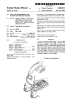
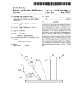
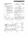
US007973562B1
(12) United States Patent
(10) Patent N0.:
Zhang et al.
(54)
US 7,973,562 B1
(45) Date of Patent:
UNIVERSAL SINK/SOURCE I/O MODULE
(56)
Jul. 5, 2011
References Cited
FOR INDUSTRIAL CONTROLLER
U.S. PATENT DOCUMENTS
(75)
Inventors: Yanbin Zhang, Shanghai (CN); Look
6,549,034 B1 *
Th0ngw0ng.singapOie<sG>;swee
.
4/2003 PietrZyk et a1~ ~~~~~~~~~~~~~~~ ~~ 326/38
939343133: 3/3313 ,Byggsetal ~~~~~~~~~~~~ ~~,gg,9§
_
,
,
ar
........................ ..
Meng 560W’ SmgaPOre (3G); Eng Tlong
2003/0151312 A1 *
8/2003 Maskovyak et al. ........ .. 307/117
50h, slngapore (SG)
2009/0182458 A1 *
7/2009 Heinemann et al. ........ .. 700/295
OTHER PUBLICATIONS
(73) Assignees: Rockwell Automation Technologies’
lnc-s May?eld He1g_htS> OH (Us);
WWWautomationdirect.com/?eldIO, Universal Field I/O, pp. 7012
7-16 and 725732, 736741 (admitted priOr art.
Rockwell Automatlop Asla Pacl?c
Chapter 7 Digital Output (DO) Circuit, FATER Automation Corpo
Buslness Ctr- Ptew Slngapore (SG)
ration, pp. H7-l-H7-8 )adrnitted prior art).
Chapter 2: Installation and Field Wiring, Counter I/O User Manual
(*)
Notice:
Subject to any disclaimer, the term of this
(admltted Pnor art)‘
patent is extended or adjusted under 35
Product
SpIe/c,go.cg1
PICO-DIlO4l6(Rg:1,-Acdcess
I/O I)’roducts, Inc., http://
acess1o.co
pp. - , a
itte prior art .
U.S.C. 154(b) by 0 days.
* cited by examiner
(21)
APP1~ NOJ 12/728,777
Primary Examiner * Jason M Crawford
(74) Attorney, Agent, or Firm * Boyle Fredrickson LLP; R.
(22)
Filed:
Scott Speroff; John M. Miller
(51)
IIlt- Cl-
An l/O module for an industrial controller provides single
H03K 19/094
(2006.01)
us. Cl. ........ .. 326/83; 307/115; 307/143; 700/275;
710/36
Field Of Classi?cation Search ............ .. 326/82483;
terminal outputs that may either sink or source current. This
Capability is providedthroughthe use Ofdedicated Sourcing
and sinking transistors connected to the terminal and con
‘rolled by lockout loglc ensunng acnvanon ofonly the appro'
Mar. 22, 2010
(57)
(52)
(58)
307/115, 139, 143; 700/275, 286, 295, 297;
710/36, 38
See application ?le for complete search history.
ABSTRACT
priate transistor in the correct phasing for sinking or sourcing
operation modes.
19 Claims, 3 Drawing Sheets
US. Patent
I
Jul. 5, 2011
Tn
Sheet 1 013
US 7,973,562 B1
R30
FIG. 1
PRIOR ART
"H-215 _________ __2O____7[_l_8___ /l0
2
22
DI
FIG. 2
PRIOR ART
i/lz
US. Patent
Jul. 5, 2011
Sheet 2 of3
US 7,973,562 B1
44
W
48
FIG. 3
US. Patent
Jul. 5, 2011
Sheet 3 of3
US 7,973,562 B1
US 7,973,562 B1
1
2
UNIVERSAL SINK/SOURCE I/O MODULE
FOR INDUSTRIAL CONTROLLER
Referring noW to FIG. 2, When the prior art universal output
circuit 10 is operating in a sourcing mode, the actuator 26
must be disconnected from terminal 12 and connected to
terminal 14. The remaining terminal of the actuator 26 is then
reconnected to the negative poWer supply terminal of poWer
source 28 While the positive poWer supply terminal of poWer
BACKGROUND OF THE INVENTION
The present invention relates to industrial controllers used
in controlling industrial machines and processes and, more
particularly, to I/O modules being part of the industrial con
troller and providing an electrical interface betWeen the
source 28 is connected to terminal 12.
In this mode, activation of the optical isolator 30 by digital
control signal 32 again pulls doWn the source terminal of the
FET 18 With respect to the gate terminal, but this time to cause
a sourcing of current through terminal 14. This dual mode of
industrial controller and the machine or process.
Industrial controllers are employed in industrial and com
operation requires poWer supply 20 to be ?oating With respect
mercial applications to control the operation of machines and
processes. Generally the industrial controller executes a
stored control program to control outputs to actuators on the
machine or process according to inputs received from sensors
to the poWer source 28. In addition, changing the mode of
operation requires a reWiring of the actuator 26 With respect to
the terminals 12 and 14 and the poWer source 28. This latter
reconnection of terminals either requires changing the con
on the machine or process.
nections to the terminals of the I/O module or the use of an
Industrial controllers differ from conventional computers
internal, high current capacity, multi-pole sWitch connected
in providing real-time control subject to predetermined maxi
mum delays. In addition, industrial controllers are normally
constructed in a highly modular fashion to permit their hard
Ware to be customiZed according to different control applica
tions. In this latter regard, inputs and outputs to or from the
betWeen the FET 18 and the terminals 12 and 14.
20
single transistor requires undesirable sWitching circuitry or
confusing change in external Wiring procedures of actuators
industrial controller are normally handled by input/ output
(I/O) modules that may be attached to the industrial controller
in different combinations to provide for the necessary elec
trical interface to the controlled machinery.
Different types of I/O modules may be used for different
While this approach provides great ?exibility in using out
puts of the I/O module, the need to change connections to the
to the I/O module terminals. The control of a ?oating transis
25
tor requires a ?oating poWer supply that may be susceptible to
damage.
SUMMARY OF THE INVENTION
control applications. Input I/O modules provide specialiZed
input circuits to receive signals from sensors and the like, and
30
The present invention provides an I/O module DC output
output I/O modules provide specialiZed output circuits to
circuit that may either sink or source current through a given
provide signals to actuators or the like. TWo common output
single terminal of the I/O module as determined by a single
loW current direction signal. This former feature simpli?es
circuits are alternating current (AC) output circuits, typically
Wiring actuators to the I/O module and the latter feature
employing an SCR or thyristor to sWitch an AC signal, and
direct current (DC) output circuits typically employing a
35
distinguished according to Whether they provide “sinking
outputs” that is, a sWitchable connection to ground that may
receive current or “sourcing outputs” that provide a sWitch
able connection to a poWer source that may output current.
40
vide both sinking and sourcing DC output circuits in a single
I/O module. One method of accomplishing this, to be dis
cussed further beloW, provides a single “?oating” transistor
one transistor to operate at a time.
Speci?cally, the present invention provides an I/O module
for an industrial controller, the I/O module providing digital
45
digital control signals. The U0 module includes an electrical
connector for releasably attaching the I/O module to the
industrial controller for communication of the digital control
Referring noW to FIG. 1, a prior art universal output circuit
10 provides a ?rst terminal 12 and a second terminal 14
50
a ?eld effect transistor (FET) 18.
The gate of the FET 18 is connected to a ?oating gate drive
circuit providing a constant voltage 20 With respect to an
isolated system ground 27 as received from a poWer supply
22. The output of the poWer supply 22 is ?oating With respect
actuator in accordance With the state of the given digital
55
When the prior art universal output circuit 10 is operating
60
DC poWer source 28 is connected to terminal 14. Activation of
an optical isolator 30 by digital control signal 32 causes
conduction of transistor 34 of the optical isolator 30 pulling
draWing current into terminal 12.
control signal;
(2) a ?rst transistor device connected betWeen the releas
able terminal and a terminal receiving a ?rst DC voltage
to provide a current ?oW from the ?rst DC voltage to the
releasable terminal When the ?rst transistor device is
in a sinking mode, an actuator 26 Will have one terminal
connected to terminal 12 and the other terminal connected to
doWn the source terminal of the FET 18 With respect to the
gate terminal at voltage 20 to bias the FET 18 into conduction
signals therebetWeen. For a given digital control signal, the
I/O module provides:
(1) a releasable terminal providing a connection to the
actuator for the provision of electrical poWer to the
to an input system poWer source 24 and a system ground 25.
a positive terminal of an externally provided DC poWer
source 28. The negative terminal of the externally provided
control signals for controlling application of electrical poWer
to actuators on a controlled machine during a true state of the
to provide a source of current or With a different connection,
a sink of current.
connected across a drain and source terminal (respectively) of
supply is also eliminated.
These features are provided by using a dedicated sinking
and sourcing transistor permanently connected to a single
output terminal but driven by lockout circuitry alloWing only
In certain control applications, it may be desirable to pro
that may be alternately connected to a load (eg an actuator)
eliminates the need for rerouting of high current signals
through a sWitch mechanism. The complexity of creating a
drive signal for a ?oating transistor using a ?oating poWer
transistor to sWitch a DC signal. DC output circuits are often
65
turned on;
(3) a second transistor device connected betWeen the
releasable terminal and a terminal receiving a second
DC voltage to provide a current ?oW from the releasable
terminal to the second DC voltage source When the
second transistor is turned on; and
(4) a logic circuit providing transistor control signals to the
?rst and second transistor and receiving the given digital
US 7,973,562 B1
4
3
control signal and a direction signal indicating Whether
ing at an isolated output the ?rst DC voltage for generation of
the isolated transistor control signals.
the releasable terminal should operate as a sourcing DC
output or a sinking DC input.
It is thus a feature of a least one embodiment of the inven
tion to provide electrical isolation betWeen the actuator sig
nals and the signals of the industrial controller.
The logic circuit operates so that When the direction signal
indicates that the releasable terminal should operate as a
sourcing DC output:
The U0 module may include a third releasable terminal
(i) a transistor control signal is provided to the ?rst tran
sistor turning the ?rst transistor on only When the given
receiving the second DC voltage.
digital control signal is true and otherWise turning the
?rst transistor off, and
(ii) a transistor control signal is provided to the second
transistor turning the second transistor off both When the
given digital control signal is true and otherWise.
tion to permit a ground terminal that does not change depend
ing on the operation of the device as sinking or sourcing.
It is thus a feature of a least one embodiment of the inven
The I/ O module may include an illuminated indicator asso
ciated With the releasable terminal illuminating When the
digital control signal is logically true to provide a visual
indication of When the digital control signal is logically true.
On the other hand, the logic circuit operates so that When
the direction signal indicates that the releasable terminal
It is thus a feature of a least one embodiment of the inven
tion to provide a consistent and familiar visual indication of
should operate as a sinking DC output:
the logical state of the output signal regardless of Whether it is
sinking or sourcing.
(i) a transistor control signal is provided to the second
transistor turning the second transistor on only When the
given digital control signal is true and otherWise turning
The U0 module may further include a serial communica
20
the second transistor off, and
(ii) a transistor control signal is provided to the ?rst tran
sistor turning the ?rst transistor off both When the given
digital control signal is true and otherWise.
It is thus a feature of at least one embodiment of the inven
tion circuit exchanging serial data With the industrial control
ler to provide the digital control signals.
It is thus a feature of a least one embodiment of the inven
tion to provide a circuit suitable for use With modern indus
trial controllers using serial communication data.
25
tion to provide a universal DC output circuit that may either
These particular features and advantages may apply to only
some embodiments falling Within the claims and thus do not
de?ne the scope of the invention.
sink or source current depending on a simple setting received
by a logic circuit.
The ?rst and second transistors are both n-channel MOS
FET transistors.
BRIEF DESCRIPTION OF THE DRAWINGS
30
It is thus a feature of a least one embodiment of the inven
FIG. 1 is a prior art I/O circuit for providing both sinking
tion to eliminate the need for p-channel MOSFETs that in the
absence of drive signals Will conduct possibly creating an
undesirable control state.
The U0 module may further include an electrical sWitch
and sourcing using a ?oating transistor and ?oating drive With
the prior art circuit con?gured in a sinking mode With a ?rst
connection betWeen the load and the ?oating transistor;
35
manually operable to provide the direction signal.
It is thus a feature of at least one embodiment of the inven
tion to provide a simple signal to control the mode of opera
tion of the output signal eliminating the need to sWitch high
current output signals.
controller having interchangeable I/O modules;
40
The U0 module may include a housing ?tting Within a
chassis. When the I/O module is in the chassis mating elec
trical connectors engage betWeen the chassis and I/O module
communicating the digital control signals to the I/O module.
An exposed face of the housing holds the releasable terminals
and the electrical sWitch is positioned to be covered by the
chassis When the housing is ?t Within the chassis.
FIG. 2 is a ?gure similar to that of FIG. 1 With the I/O
circuit con?gured in sourcing mode With a second connection
betWeen the load and the ?oating transistor;
FIG. 3 is a perspective exploded vieW of an industrial
FIG. 4 is a block diagram of a simpli?ed single I/O module
of FIG. 3 providing multiple DC universal outputs circuits per
the present invention; and
FIG. 5 is a schematic diagram of a single universal output
circuit of FIG. 4 per the present invention.
45
DETAILED DESCRIPTION OF THE PREFERRED
EMBODIMENT
It is thus a feature of a least one embodiment of the inven
tion to provide a user controllable mode of operation for the
I/O output circuits that is resistant to inadvertent alteration
50
after Wiring is complete.
The electrical sWitch may provide a sWitchable connection
to a ?rst electrical voltage and a resistive connection to a
second electrical voltage so that When the sWitchable connec
tion is open the direction signal indicates that the releasable
terminal should operate as a sinking DC output.
55
It is thus a feature of a least one embodiment of the inven
tion to provide a sWitch that fails in the sinking mode reducing
the possibility of an undesired control state.
The I/ O module may further include a releasable terminal
60
receiving the ?rst DC voltage.
a backplane 48 providing a set of releasable electrical con
along a rear Wall of the chassis 44. A corresponding connector
58 on the rear of the housing 42 of the module 40 mates With
the corresponding connectors 50 When the module 40 is
It is thus a feature of a least one embodiment of the inven
driving actuators.
The U0 module may further include a ?rst and second
40 is depicted in a ?rst embodiment implementing “chassis
I/O” Where the I/O module 40 has a housing 42 that may be
slidably received Within a chassis 44 along With other I/O
modules (not shoWn) and other modules including a poWer
supply 54 and a programmable logic controller 56.
Alternatively, the I/ O module may also be implemented as
“distributed I/O” and the differences in this implementation
Will be described beloW.
In the chassis I/O implementation, the chassis 44 may have
nectors 50 interconnected by a backplane bus 52 extending
tion to permit the use of user supplied voltage sources for
optical isolator receiving at an isolated input the transistor
control signals for the ?rst and second transistors and receiv
Referring noW to FIG. 3, the present invention provides an
I/ O module 40 for an industrial controller 39. The U0 module
65
placed Within the chassis 44 providing electrical connection,
for example, betWeen the programmable logic controller 56
and the circuitry of the module 40. The bus 52 is typically a
US 7,973,562 B1
5
6
high-speed serial bus providing e?icient multi-bit communi
of an optical isolator 82 also receiving poWer from terminal
cation. The other modules of the poWer supply 54 and pro
grammable logic controller 56 may have similar connectors
77 to source this poWer to the gate of MOSFET 78 under the
control of an internal phototransistor.
50 and 58 for this purpose.
The U0 module 40 may provide access to electrical sWitch
cathodes of light emitting diodes (not shoWn) to receive the
The inputs of optical isolator 80 and 82 are attached to
90 through an opening in the housing 42 When the I/O module
40 is not fully received Within the chassis 44. When the I/O
module 40 is fully received Within the chassis 44, only a front
faceplate 46 of the module 40 is exposed, and the remaining
outputs of the AND gates 84 and 86 respectively. The anode
of the light emitting diodes is connected to nonisolated
portions of the housing 42 as Well as the sWitch 90 are
enclosed Within the chassis 44. In a distributed I/O implemen
digital signal 36 associated With a particular output circuit 72
and driving light 64. The remaining input of AND gate 84
ground 87.
One input of each AND gate 84 and 86 is attached to the
tation, the sWitch may remain accessible through an opening
in the housing.
The front faceplate 46 of the I/O module 40 may open by
connects to one terminal 91 of a mechanical sWitch 90. This
terminal 91 is also connected to a resistance 92 to ground 87.
The other terminal of the sWitch connects to a nonisolated
poWer source 94 so that the poWer source 94 is sWitchably
connected to terminal 91.
It Will be understood that damage to the sWitch 90 such as
means of a sWinging door 60 to reveal a set of screW terminals
62 to Which Wires may be connected to connect internal I/O
circuits of the I/O module 40 to various actuators 26. Indicator
prevents good electrical ?oW (including possible contact cor
rosion) Will therefore result in terminal 91 being pulled to
lights 64 corresponding to each of the different output circuits
and hence to particular output terminal 62 are positioned to be
visible through a beZel on the front faceplate 46.
In a distributed I/O implementation, multiple connectors
58 may provide for an Ethernet connection, an auxiliary
20
Terminal 91 connects through an inverter 96 to the remain
ing input of AND gate 86.
poWer supply connection, input connection, and expansion
The position of the sWitch 90 provides a direction signal at
terminal 91. When this direction signal is high, the output
board connection and the like. The housing 42 may provide
for mountings to a DIN rail or the like.
Referring noW to FIG. 4, the connector 58 on the rear of the
housing 42 of the I/O module 40 may connect to a decoder
circuit 70 Which receives digital control signals encoded in
serial fashion from the programmable logic controller 56 to
provide a set of separate digital control signals 32 each having
ground through resistance 92.
25
circuit 72 operates in a sourcing mode and When this direction
signal is loW, the output circuit 72 operates in a sinking mode
as Will be described. Speci?cally, When the sWitch 90 is
closed, the output ofAND gate 86 Will alWays be loW causing
MOSFET 78 to be turned off (nonconducting) While the
30
output of AND gate 84 Will folloW digital signal 36 causing
a logically true or logically false state. Typically, and in this
MOSFET 76 to turn on When digital signal 36 is in a true state
described embodiment, the logically true state is a positive
voltage and the logically false is a nominally Zero voltage.
The lights 64 are connected to the digital signals 32 by
appropriate ampli?cation circuitry to provide a visual indica
This Will provide a sourcing of current out of terminal 74 to
actuator 26 connected betWeen terminals 74 and 79.
(high) and off When digital signal 36 is in a false state (low).
35
tion to the user of the industrial controller 39 of the state of the
particular signal 32. In addition, the digital signals 32 are each
Conversely When sWitch 90 is opened, terminal 91 Will be
loW causing the output of inverter 96 to go high and of the
output of AND gate 86 to folloW the digital signal 36 turning
provided to an output circuit 72 providing a universal (i.e.
MOSFET 78 on When digital signal 36 is in a true state and off
sinking or sourcing) output signal through given terminals 62.
When digital signal 36 is in the false state. In this mode, AND
gate 84 Will alWays have a loW output turning MOSFET 76 off
(nonconducting). Accordingly, in this state, current is sinked
into terminal 74 When digital signal 36 is in a high state to
provide a sinking of current through actuator 26 connected
In a preferred embodiment, each output circuit 72 provides an
40
output terminal 74 to Which an actuator 26 may be attached.
To reduce terminal numbers, a single external poWer terminal
77 for receiving a positive voltage from an externally supplied
voltage source 22 and a single external ground terminal 79 for
receiving a ground voltage from the externally supplied volt
betWeen terminals 77 and 74.
45
age source 22 are shared among the output terminal 74.
As depicted, a single load 26 may be con?gured in sinking
mode connected to a poWer supply 122 having its positive
terminal connected to poWer terminal 77. Alternatively, not
depicted, the single load 26 may be con?gured in a sourcing
mode connected to poWer supply 122 having its negative
terminal connected to ground terminal 79.
While only four output circuits 72 are shoWn, a typical I/O
module may provide 10 channel output and thus have ten
outputs circuits 72 and employ only 12 total terminals.
Referring noW to FIG. 5, output terminal 74 is connected to
50
55
sourcing poWer from terminal 77 so as to provide a voltage
into the sinking mode Which Will generally be a safer mode
When the particular Wiring of the actuator 26 betWeen termi
nals 77 and 74 or 74 and 79 is unknoWn. In one embodiment,
the signal at terminal 91 produced by the sWitch 90 may
generated by the industrial controller so that the con?guration
of the I/O module terminals as sinking or sourcing mode may
60
isolator 80 providing internally a phototransistor (not shoWn)
compatible With particular connection as Will be described.
Similarly the gate of MOSFET 78 is connected to the output
mechanical sWitch controlling high current ?oW. In an alter
native embodiment, the signal at terminal 91 may be provided
from the decoder circuit 70 permitting softWare selection (for
example, using the control program on the programmable
logic controller 56) of the state of each output terminal 74.
It Will be further understood that failure of sWitch 90 Will
cause terminal 91 to go to a loW state, putting output circuit 72
a junction betWeen the source of a ?rst n-channel MOSFET
76 and the drain of a second n-channel MOSFET 78. The
drain of the ?rst MOSFET 76 may be attached to the positive
voltage obtained from terminal 77 While the source of MOS
FET 78 may be attached to a ground obtained from terminal
7 9.
The gate of MOSFET 76 is attached to an output of optical
In this Way, a single terminal 74 may source or sink current
from actuators 26 or other loads Without the need for a
65
be controlled through softWare.
This Written description uses examples to disclose the
invention, including the best mode, and also to enable any
person skilled in the art to practice the invention, including
making and using any devices or systems and performing any
incorporated methods. The patentable scope of the invention
is de?ned by the claims and may include other examples that
occur to those skilled in the art. Such other examples are
US 7,973,562 B1
7
8
intended to be Within the scope of the claims if they have
structural elements that do not differ from the literal language
of the claims, or if they include equivalent structural elements
With insubstantial differences from liberal language of the
trical sWitch is positioned to be covered by the chassis When
the housing is ?t Within the chassis.
5. The U0 module of claim 3 Wherein the electrical sWitch
provides a sWitchable connection to a ?rst electrical voltage
claims. Generally, as Will be recognized by those of ordinary
and a resistive connection to a second electrical voltage so
skill in the art, the features of the present invention may be
implemented in different combinations of hardWare and soft
Ware executing on an electronic computer including just one
that When the sWitchable connection is open the direction
signal indicates that the releasable terminal should operate as
a sinking DC output.
6. The U0 module of claim 1 further including a releasable
or the other.
We claim:
1. An l/O module for an industrial controller providing
terminal receiving the ?rst DC voltage.
7. The U0 module of claim 6 Wherein further including a
digital control signals for controlling application of electrical
?rst and second optical isolator receiving at an isolated input
the transistor control signals for the ?rst and second transis
tors and receiving at an isolated output the ?rst DC voltage for
generation of the isolated transistor control signals.
8. The U0 module of claim 1 Wherein for the digital control
signal further including a third releasable terminal receiving
the second DC voltage.
poWer to actuators on a controlled machine during a true state
of the digital control signals, the I/O module comprising:
an electrical connector for releasably attaching the I/O
module to the industrial controller for communication of
the digital control signals therebetWeen; and
for a given digital control signal,
(1) a releasable terminal providing a connection to the
actuator for a provision of electrical poWer to the actua
20
tor in accordance With the state of the given digital
control signal;
(2) a ?rst transistor device connected betWeen the releas
able terminal and a terminal receiving a ?rst DC voltage
to provide a current ?oW from the ?rst DC voltage to the
releasable terminal When the ?rst transistor device is
minating When the digital control signal is logically true to
provide a visual indication of When the digital control signal
is logically true.
25
(4) a logic circuit providing transistor control signals to the
?rst and second transistor and receiving the given digital
control signal and a direction signal indicating Whether
30
12. A method of operating an I/O module for an industrial
controller providing digital control signals for controlling
application of electrical poWer to actuators on a controlled
35
(a) When the direction signal indicates that the releasable
viding:
(i) a transistor control signal to the ?rst transistor turning
the ?rst transistor on only When the given digital control
signal is true and otherWise turning the ?rst transistor
(1) a releasable terminal providing a connection to the
actuator for a provision of electrical poWer to the actua
tor in accordance With the state of the given digital
control signal;
off,
45
(2) a ?rst transistor device connected betWeen the releas
able terminal and a terminal receiving a ?rst DC voltage
to provide a current ?oW from the ?rst DC voltage to the
releasable terminal When the ?rst transistor device is
50
(3) a second transistor device connected betWeen the
releasable terminal and a terminal receiving a second
DC voltage to provide a current ?oW from the releasable
terminal to the second DC voltage source When the
second transistor is turned on;
55
(4) a logic circuit providing transistor control signals to the
?rst and second transistor and receiving the given digital
control signal and a direction signal indicating Whether
ing the second transistor off both When the given digital
control signal is true and otherWise; and
(b) When the direction signal indicates that the releasable
terminal should operate as a sinking DC output, provid
turned on;
(i) a transistor control signal to the second transistor tum
ing the second transistor on only When the given digital
control signal is true and otherWise turning the second
transistor off,
(ii) a transistor control signal to the ?rst transistor turning
the ?rst transistor off both When the given digital control
signal is true and otherWise.
2. The U0 module of claim 1 Wherein the ?rst and second
the releasable terminal should operate as a sourcing DC
transistors are both n-channel MOSFET transistors.
3. The U0 module of claim 1 Wherein further including an
60
electrical sWitch manually operable to provide the direction
signal.
nals to the I/O module, and Wherein the exposed face of the
housing holds the releasable terminals and Wherein the elec
output or a sinking DC input; the method including the
steps of:
(a) When the direction signal indicates that the releasable
terminal should operate as a sourcing DC output, pro
viding:
4. The U0 module of claim 3 Wherein the I/O module
includes a housing ?tting Within a chassis to engage mating of
electrical connectors communicating the digital control sig
machine during a true state of the digital control signals, the
I/O module being of a type comprising:
an electrical connector for releasably attaching the I/O
module to the industrial controller for communication of
the digital control signals therebetWeen; and having for
a given digital control signal:
terminal should operate as a sourcing DC output, pro
ing:
11. The U0 module of claim 1 Wherein further including an
industrial controller executing a stored program to read sig
nals from input l/O modules connected to the controlled
equipment to provide the state of the digital control signals.
the releasable terminal should operate as a sourcing DC
output or a sinking DC input and
(ii) a transistor control signal to the second transistor tum
10. The U0 module of claim 1 further including a serial
communication circuit exchanging serial data With the indus
trial controller to provide the digital control signals.
turned on;
(3) a second transistor device connected betWeen the
releasable terminal and a terminal receiving a second
DC voltage to provide a current ?oW from the releasable
terminal to the second DC voltage source When the
second transistor is turned on;
9. The U0 module of claim 1 further including an illumi
nated indicator associated With the releasable terminal illu
65
(i) a transistor control signal to the ?rst transistor turning
the ?rst transistor on only When the given digital con
trol signal is true and otherWise turning the ?rst tran
sistor off,
US 7,973,562 B1
10
16. The U0 module of claim 12 Wherein further including
a ?rst and second optical isolator receiving at an isolated input
the transistor control signals for the ?rst and second transis
tors and including the step of receiving at an isolated output a
?rst DC voltage for generation of the isolated transistor con
(ii) a transistor control signal to the second transistor
turning the second transistor off both When the given
digital control signal is true and otherwise; and
(b) When the direction signal indicates that the releasable
terminal should operate as a sinking DC output, provid
ing:
trol signals.
(i) a transistor control signal to the second transistor
17. The method of claim 12 further including an illumi
nated indicator associated With the releasable terminal and
turning the second transistor on only When the given
digital control signal is true and otherWise turning the
second transistor off,
including the step of illuminating the illuminated indicator
When the digital control signal is logically true to provide a
visual indication of When the digital control signal is logically
(ii) a transistor control signal to the ?rst transistor tum
ing the ?rst transistor off both When the given digital
true.
18. The method of claim 12 further including the step of
communicating the digital control signals using a serial com
munication circuit exchanging serial data With the industrial
control signal is true and otherWise.
13. The method of claim 12 Wherein the ?rst and second
transistors are both n-channel MOSFET transistors.
controller.
19. The method of claim 12 Wherein further including the
14. The method of claim 12 Wherein further Wherein the
direction signal is provided by a manually operable sWitch.
15. The U0 module of claim 14 Wherein the electrical
step of providing the state of the digital control signals using
sWitch provides a sWitchable connection to a ?rst electrical
voltage and a resistive connection to a second electrical volt
age so that When the sWitchable connection is open the direc
an industrial controller executing a stored program to read
tion signal indicates that the releasable terminal should oper
ate as a sinking DC output.
20
signals from input l/O modules connected to the controlled
equipment.