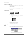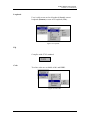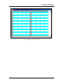
1
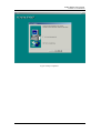
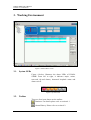
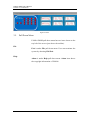
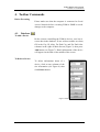
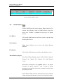
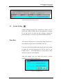
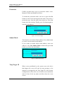
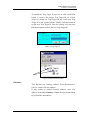
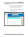
FOM16TM
Universal Fiber Multiplexer
SNMP User’s Manual
Version: 1.4
2004/04
FOM16 SNMP User’s Manual
FOM16-V1.4-20040430
FOM16 SNMP User’s Manual
Table of Contents
1.
INTRODUCTION................................................................................................1
2.
INSTALLATION .................................................................................................3
2.1.
2.2.
3.
4.
SOFTWARE/HARDWARE REQUIREMENTS .........................................................3
INSTALLATION STEPS ......................................................................................4
WORKING ENVIRONMENT ...........................................................................6
3.1.
3.2.
3.3.
3.4.
SYSTEM LEDS ................................................................................................6
TOOLBAR ........................................................................................................6
DEVICE TREE ..................................................................................................7
PANEL .............................................................................................................7
3.5.
PULL DOWN MENU .........................................................................................8
TOOLBAR COMMANDS ..................................................................................9
4.1.
4.2.
4.3.
DATABASE .......................................................................................................9
ALARM HISTORY ...........................................................................................10
SYSTEM SETTING .......................................................................................... 11
5.
CONNECTION ..................................................................................................15
6.
SUMMARY REPORT .......................................................................................16
7.
PERFORMANCE ..............................................................................................18
8.
THRESHOLD ....................................................................................................20
-i-
FOM16 SNMP User’s Manual
FOM16-V1.4-20040430
1. INTRODUCTION
FOM16 provides SNMP agent managed by remote SNMP
manager. FOM16 SNMP is a graphical user interface (GUI)
running on Ethernet connected by PC. FOM16 features a
SNMP-v1 protocol that access MIB-2, RFC1406 and
RFC1407.
MIB-2 is a RFC1213 management information base on
network management of TCP/IP based Internets. RFC1406
defines managed objects for DS1 and E1 interface while
RFC1407 defines the managed objects for DS3 and E3
interface.
-1-
FOM16 SNMP User’s Manual
FOM16-V1.4-20040430
1.1.
SNMP
SNMP is a request-response program used to transfer
management information between entities which act in
either manager or agent role. Managers are often
configured as management stations and agents are often
configured as managed nodes. A manager can also act as an
agent in both vertical (hierarchical) and horizontal
(distributed) relationships. Likewise, a physical node may
be managed by multiple agents, and an agent might manage
a multiple physical nodes. Hence, when we use the
prototypical
management
station/managed
node
perspective for the sake of simplicity and clarity of
presentation, such practice is not meant to preclude other
forms of SNMP interactions.
Each management device or application contains
monitoring and (possibly) control instrumentation. The
agent accesses this instrumentation and represents its
access to the manager via a MIB (Management Information
Base), filtered by the SNMP security mechanisms.
Management applications communicate with agents via
SNMP to monitor and (possibly) control managed devices
or applications.
-2-
FOM16 SNMP User’s Manual
FOM16-V1.4-20040430
2. Installation
2.1.
Software/Hardware Requirements
The following hardware and software components have to
be installed before the installation of FOM16 SNMP.
1. CPU: IBM Compatible, 200 MHz or Higher
2. OS: Microsoft Windows 98, NT4, NT2000.
3. RAM: 64M Minimum
4. HD: 50MB or Higher.
5. Monitor: VGA color (1024*768 Large Fonts) or Better
6. Mouse/Keypad
7. Ethernet Interface
-3-
FOM16 SNMP User’s Manual
FOM16-V1.4-20040430
2.2.
Installation Steps
z
z
z
z
z
Start Windows Operating System if it is not running.
Exit all running Windows programs before installing
FOM16 SNMP program.
Insert the FOM16 SNMP distribution disk into CD
drive.
Execute Setup.exe
The following window appears on the screen after
double-clicking the Setup icon.
Figure 1 Preparing for Setup
z
The Setup Wizard will guide user to install FOM16
SNMP step by step.
z
After the setup is completed, the screen displays Figure
2. User can chose to launch the FOM16 SNMP by
clicking <Yes, Launch the program file> the check
box or to complete and exit the setup process by
clicking <Finish> button.
-4-
FOM16 SNMP User’s Manual
FOM16-V1.4-20040430
Figure 2 Setup Completed
-5-
FOM16 SNMP User’s Manual
FOM16-V1.4-20040430
3. Working Environment
Figure 3 FOM16 Main Screen
3.1.
System LEDs
Figure 4 below, illustrates the alarm LEDs of FOM16
SNMP. From left to right, it indicates major, minor,
near-end, far-end alarms, abnormal loopback status and
alarm cut off.
Figure 4 System LEDs
3.2.
Toolbar
There are four icons shown on the toolbar:
Database: For details please refer to section 4.1.
Alarm History: Please refer to section 4.2.
-6-
FOM16 SNMP User’s Manual
FOM16-V1.4-20040430
System Setting: Details are listed in section 4.3.
ACO (Alarm Cut Off): This is used to turn off the
Audio Alarm.
3.3.
Device Tree
The device tree shows what and where the devices are
available. The first level of the device tree is FOM16, the
second level is the city name and the third level is the alias
for FOM16. The third layer is accessible to the user by
click the right button of the mouse while the curser is on
the alias to manipulate the equipment.
In the sample device tree shown in Figure 5, Taipei has one
FOM16 equipment called Stn-4 which is connected to a far
end FOM16 called Stn-5.
Figure 5 Device Tree
3.4.
Panel
Six buttons and 18 LEDs are shown on the panel below, the
18 LEDs indicates the status of the 16 E1/T1 channels and
2 optical fibers.
By clicking OPTICAL or DS1/E1, user is able to choose
object to manipulate.
-7-
FOM16 SNMP User’s Manual
FOM16-V1.4-20040430
Figure 6 Panel
3.5.
Pull Down Menu
FOM16 SNMP pull down menu has two items locate on the
top left of the screen (just above the toolbar).
File
Exit is under File pull down menu. User can terminate the
system by choosing File/Exit.
Help
About is under Help pull down menu. About item shows
the copyright information of FOM16.
-8-
FOM16 SNMP User’s Manual
FOM16-V1.4-20040430
4. Toolbar Commands
Before Executing
Please make sure that the computer is connected to Local
Access Network before executing FOM16 SNMP to avoid
damage to the computer.
4.1.
Database
To Add a Device
Before remote controlling the FOM16 devices, user has to
create data in the database. If user wishes to add a new data,
fill in the City, IP, Alias, Far End City and Far End Alias
columns in the right of Main Screen (Figure 3) then press
Add button (see Figure 7). Detail information of the device
will appear on the table in the middle of the screen.
To Delete a Device
To delete information about of a
device, click on any columns of the
site information (see Figure 8) then
click Delete button.
Figure 7 Add a Site to the Database
-9-
FOM16 SNMP User’s Manual
FOM16-V1.4-20040430
Figure 8 Sample Database Table
4.2.
Alarm History
FOM16 SNMP provides Alarm History Report function. To
execute this function, select a FOM16 device from the
device tree. FOM16 is capable to store up to 30 alarm
records.
Get Button
Click on the Get button to allow the system to get the data
from FOM16 device.
Clear Button
Clear button allows user to clear the Alarm History
database.
Exit Button
Click on the Exit button to go back to the database screen.
Alarm History Report
The Alarm History Report consists of five folders: Optical,
Channel 1-4, Channel 5-8, Channel 9-12 and Channel
13-16.
Information contained in the Optical folder is the alarm
messages of optical channels 1 and 2, status of alarm
messages (near and far ends, major or minor), and the time
the alarm occurred.
Each Channel folder contains information for four channels.
Alarm message and the time occurred are listed in the table.
-10-
FOM16 SNMP User’s Manual
FOM16-V1.4-20040430
Figure 9 Sample Alarm History Report
4.3.
System Setting
System Setting provides five functions to allow user to
check and change FOM16 device time and date, set target
IP for the device to send out trap message, amend the
protection mode, set Gateway IP and set Subnet Mask IP.
Time\Date
This function allows user to check and change the device’s
date and time to the current Time\Date of the PC.
User has to click on the Get button first to allow the system
to attain the current Time\Date for the PC and for the
FOM16 device. Press Set button to set the device’s time
and date to the PC’s time and date.
After the setting, user can check the device’s current
time\date by pressing the Get button.
Figure 10 Tim\Date Page
-11-
FOM16 SNMP User’s Manual
FOM16-V1.4-20040430
Protection
FOM16 provides three types of protection modes: Auto,
Manual to Work and Manual to Protect.
To amend the protection mode, user has to press the Get
button to retrieve the current protection mode. Then select a
protection type from the pull down menu bar. Press Set
button after the selection. Finally, press Get button again to
check the amendment.
Figure 11 Protection Page
Subnet Mask
This function sets Subnet Mask address. Press Get button
to retrieve current subnet mask address.
If user wishes to amend subnet mask address, enter new
address in the New Subnet Mask column then press Set
button to perform the amendment.
Figure 12 Subnet Mask Page
Trap Target IP
When events predefined by the system occur, the device
that happen the event will send out trap message to the
manager (as assigned by the Trap Target IP in the System
Setting Section). The device tree will shows an exclamation
mark in front of the city name and alias where the event
occurs.
-12-
FOM16 SNMP User’s Manual
FOM16-V1.4-20040430
To amend the Trap Target IP, user has to click on the Get
button to retrieve the current Trap Target IP set. If user
desires to change the Trap Target IP, key in the new Trap
Target IP in the second column. Finally click Set button to
set the new Trap Target IP. After the setting, user can press
Get button again to check the new Trap Target IP.
Figure 13 Trap Target IP
Figure 14 Trap Exclamation Mark
Gateway
This function sets Gateway address. Press Get button to
retrieve current Gateway address.
If user wishes to amend Gateway address, enter new
address in the New Gateway column then press Set button
to perform the amendment.
-13-
FOM16 SNMP User’s Manual
FOM16-V1.4-20040430
Figure 15 Gateway Page
-14-
FOM16 SNMP User’s Manual
FOM16-V1.4-20040430
5. Connection
Double click the alias in device tree to build up session via
SNMP. The visual panel indicates when equipment/signal
failures are detected. The different alarm severity levels are
provided for all possible events and conditions.
The visual panel provides individual LED indication for
local alarm, remote alarm, loopback, aggregate LOS and
each T1/E1 channel LOS as well.
Figure 16 Built-up Connection
-15-
FOM16 SNMP User’s Manual
FOM16-V1.4-20040430
6. Summary Report
Click any of the six buttons on the panel to access the
channel information.
The Control button displays a summary report of channel.
The summary information lists following parameters for
each channel.
a. Optical Channel
z
Optical menu
There are sub-menus under Service and Loopback
menu, please refer to the Service section under b. E1
Channel Menu sections described below.
Performance: Please refer to section 7.
Threshold: Please refer to section 8
b. E1 Channel Menu
Service
Service of each channel can be set to In Service oar Out of
Service.
Figure 17 Service status
-16-
FOM16 SNMP User’s Manual
FOM16-V1.4-20040430
Loopback
User is able to turn on local loopback (Local), remote
loopback (Remote) or turn off a loopback (N\A).
Figure 18 Loopback
EQ
Complies with G.703 standard.
Code
Two line codes are available: AM1 and HDB3.
Figure 19 Line code
-17-
FOM16 SNMP User’s Manual
FOM16-V1.4-20040430
7. Performance
FOM16 SNMP provides performance data collection
function. To access this function, click on the OPTICAL or
DS1/E1 button on the panel. The performance parameters
provided are as following:
(a) For T1/E1 Input port:
Near-End
Far-End
T1 Tributary
CV, ES
CV, ES
E1 Tributary
CV, ES
CV, ES
(b) For Aggregate:
Aggregate of FOM16
CV, ES, SES, UAS
CV, ES, SES, UAS
Near-End
Far-End
The historical performance data include 15-minute interval
for the latest 24 hours, total 24-hour interval for the latest 7
days.
Click on the buttons displayed on Figure
20 to get the desires data.
Clear button reset the displayed button.
Press Exit button to go back to the
previous performed function and
terminate performance function.
Figure 20 Edit
Performance Button
-18-
FOM16 SNMP User’s Manual
FOM16-V1.4-20040430
Figure 21 Sample Performance Report
-19-
FOM16 SNMP User’s Manual
FOM16-V1.4-20040430
8. Threshold
To access this function, click on the OPTICAL or DS1/E1
button on the panel.
Click on the Get button to retrieve current threshold
settings.
To amend the threshold settings,
place the cursor of the mouse on
the Items column that user
wishes to change. The type of
threshold will be listed on the
first column of Figure 22 and the
threshold value is listed in the
second column. User can amend
the value in the second column.
Press Set button to change the
value of selected Performance
Item to the new value entered by
user.
Figure 22 Edit
Threshold Buttons
Or press Set/All to amend the value of all Performance
Items to the new value entered in the second column.
Figure 23 Sample Threshold Report
-20-