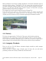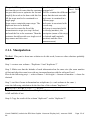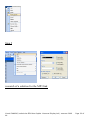
1
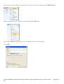
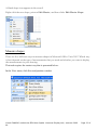
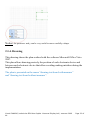
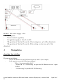
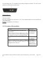
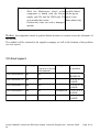
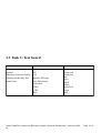
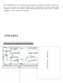
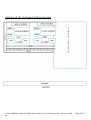
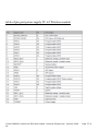
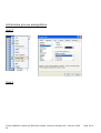
Lionel CAMOUS Polytech’Nice-Sophia 1645 route des lucioles 06410 BIOT Technician Work placement report– summer 2009 Multimedia Automatic Vehicle Location Andrew Bowler/Kevin Morrison Hanover Displays Limited Unit 24, Cliffe Industrial Estate, Lewes, East Sussex, BN8 6JL, UK. Lionel CAMOUS/ technician EPU Nice-Sophia –Hanover Display Ltd / summer 2009 44 Page 2 of Lionel CAMOUS/ technician EPU Nice-Sophia –Hanover Display Ltd / summer 2009 44 Page 3 of ACKNOWLEDGMENTS I would like to thank several people who have been of a great help and have followed me all along the internship. I would especially like to thank the following people: Mr Steve Colquhoun, for giving me the chance to do this internship. Mr Tim Marc for accepting me in the MAVL department. Mr Andrew Bowler and Mr Kevin Morrison, for having guided me throughout my tasks by giving me a better approach to the problem but also for their availability. Mrs Silvie Icart , for her kindness and her Investissment. Mrs Christine Enouf , for her help in the traduction of my report but also in the life of every days. Mrs Valerie Mall, for having facilitated my integration into the company but also in the life of every days. Mr Faris Bilal , for all his advice and his help in my tasks. Finally, I would like emphasize the simplicity and kindness of all employees of the company which have been mentioned previously but also all of the other that have participated to my integration in the company. A thought to Mike Siverns who left us too soon. Lionel CAMOUS/ technician EPU Nice-Sophia –Hanover Display Ltd / summer 2009 44 Page 4 of Table of content ACKNOWLEDGMENTS………………………………………………………..page 3 Table of content…………………………………………………………………..page 4 illustrations table, appendix table and Tasks table..............................................page 5-6 INTRODUCTION.................................................................................page 7 CHAPTER 1: ABOUT THE COMPANY HANOVER DISPLAYS o 1.1 Company Profile....................................................................page 8 o 1.2 Factory.................................................................................page 8 o 1.3 Company Products.................................................................page 9-10 CHAPTER 2 : SOFTWARE TASKS o 2.1 Task 1: Information process.................................................page 11-12 2.1.1 Manipulation.............................................................page 11 o 2.2 Task 2 : MP3 links............................................................page 13-14 2.2.1 Research of a solution..................................................page 13 2.2.2 Manipulation............................................................page 13 o 2.3 Task 3: Test board...............................................................page 15-21 2.3.1About Microsoft Office Visio........................................page 15 2.3.2 Measurement.............................................................page 15 2.3.3 Skills needed............................................................page 16 2.3.4 Drawing...................................................................page 21 CHAPTER 3 : HARDWARE TASKS o 3.1. Task 1 : Hancis power control..............................................page 22-24 3.1.1 Connecting and running the board.................................page 22 3.1.2 Manipulation.............................................................page 23 3.1.3 Progress report............................................................page 24 o 3.2 Task 2: TC-65 Wireless module............................................page 25-29 3.1.1 Power supply of the module........................................page 26 3.1.2 Check the communication with the terminal......................page 27 3.1.3 Location of the problem...............................................page 28 3.1.4 Test report................................................................page 29 o 3.3Task 3: Test board..............................................................page 30-32 3.3.1 Description of the device.............................................page 31 3.3.2 How do you do the test board in three step.....................page 32 CONCLUSION…………………………………………………………….….page 33 APPENDIX………………………………………………………………...page 34-41 Lionel CAMOUS/ technician EPU Nice-Sophia –Hanover Display Ltd / summer 2009 44 Page 5 of Appendix table NAME drawing of the test board with measure drawing of the test board without measure table of pin part power supply TC-65 Wireless module information process : manipulation research of a solution for the MP3 link MP3 link : execution 1 MP3 link : execution 2 cheking the interface for the Hancis power control Hancis power control: adjust the value for testing LOCATION P 34 P 35 P 36 P 37-38 P 38 P 39 P 39 P 40 P 41 Tasks table NAME DESCRIPTION TYPE LOCATION Lionel CAMOUS/ technician EPU Nice-Sophia –Hanover Display Ltd / summer 2009 44 Page 6 of About the companyFind the information Research Hanover display ltd necessary for the proper conduct of the internship Information process Processing of the Software presentation of information supplied by the customer MP3 link Create MP3 link for each Software stop Test board visio Drawing the plan Software H a n c i s p o w e rSetting time values and Hardware control Testing T C - 6 5 W i r e l e s sInvestigation of faulty Hardware module module Test board Fixing and wiring of Hardware devices needed for test P 8-10 P 11-12 P 13-14 P 15-21 P 22-25 P 26-29 P 30-32 INTRODUCTION This two-month training, which concluded my second year engineering school, was performed at Hanover Displays Ltd (Great Britain) in their MAVL department. As engineer’s duties might involve the supervision of technicians, this internship dealt with technician work. Lionel CAMOUS/ technician EPU Nice-Sophia –Hanover Display Ltd / summer 2009 44 Page 7 of For the need of the company, several tasks have been realised. Each task is of equal importance and no one single task is important enough to be presented alone. Consequently this report will deal with several projects that were finalised during my training. The MAVL department works as much on the hardware part as on the software part, this is the reason why we can find hardware and software tasks. Each task will be described and the solution to carry out this task will be given. CHAPTER 1: ABOUT THE COMPANY HANOVER DISPLAY Ltd .1 Company Profile Lionel CAMOUS/ technician EPU Nice-Sophia –Hanover Display Ltd / summer 2009 44 Page 8 of Hanover Displays Ltd is Europe’s leading manufacturer of electronic destination signs for the public transport industry. Established in 1985, the company has consistently grown and developed, continually refining its product range to meet the specific demands of customers. Hanover is an ISO 9001 and ISO 14001 certified company. Its Head office and major production facility is based in Lewes, England. The company has recently opened a production unit in Chicago USA. It has sales and service centres at various locations around the world to provide local support to all customers.The company also has its own subsidiary in France, Italy, Spain, Australia, and USA and most recently in Denmark supporting the Scandinavian market. 1.2. Factory The factory has approximately 33,000 sq ft of floor space which includes production, administration, sales, engineering, research and development. Hanover currently employs about 70 full time production staff producing up to 3,000 units per month on a single shift. If required, Hanover can run double shifts to ensure delivery times are always maintained. 1.3. Company Products There are well over 250, 000 Hanover destination displays installed on public transport vehicles around the world. Hanover provides a complete range of display signs for front, side, rear and interior positioning, which fit all currently available bus and coach models. Lionel CAMOUS/ technician EPU Nice-Sophia –Hanover Display Ltd / summer 2009 44 Page 9 of The company also supplies Global Positioning Systems, Voice Announcement Systems, Wireless Data Transfer Systems, Multi-media On-bus Passenger information Display, as well as, street-based displays. You can find the main products that I had to deal with during my internship below: Interior LED signs Provide on-board passenger information such as: - Advertising Messages -Next Stop information, -Bus Stopping Sign controllers ERIC and DERIC . controller, which provide the driver with easy to use facilities for selecting the required destination, the Eric+ & Deric+. As well as storing the destination database and sending messages to the signs, the controllers can also monitor the performance of the displays Hancis AVC The Hancis product group has been developed to provide a robust centralised computer system powerful enough to operate multi-media screens . The Hancis AVC (Audio Visual Computer) provides the operator with video, audio & GPS Lionel CAMOUS/ technician EPU Nice-Sophia –Hanover Display Ltd / summer 2009 44 Page 10 of within a single unit and can be placed anywhere within the vehicle. Notice : It exists also The Hancis AOC (Audio Only Computer) Multimedia flat screen Hanover's Multimedia Displays bring a new standard in display quality and functionality to on-bus passenger information. These displays are based on bright highresolution TFT flat panels driven by a powerful multimedia processor capable of processing rich graphic images and real-time full-screen video and audio. They offer significant potential for generating revenue through advertising. Keylo portable loader The Keylo has been developed to make the process of transferring destination lists to vehicle based sign controllers more convenient. Previously, an ERIC+ or DERIC+ sign controller, configured as a Data Loader, was used to transfer the data from the PC to the sign controller. The Keylo offers the additional advantages that it is small, portable, and robust and fits easily into the user's pocket. In addition no transfer cable is required. CHAPTER 2: SOFTWARE PROJECT .1 Task 1 :Information process DESCRIPTION FILE SUPPLIED IT SKILLS NEEDED Lionel CAMOUS/ technician EPU Nice-Sophia –Hanover Display Ltd / summer 2009 44 Page 11 of The goal of This project is: re-create a stop spread sheet excel Microsoft Excel 2003 list from the set of routes that the customer “original.xls” has provided so as to optimize the list and This file contains the different and 2007 simplify the work to be done with this list. routes that the train can take. All the stops need to be contained in a Each route is contained in a single page different page. Some routes contain the same stops. The Each route is associated with duplicate have to be deleted. several stop. I also need to create the list of the Each stop is associated with inconsistencies stops (see step 6 below) the id stop (number), the and send the list to the customer. Then the description (name of the stop), customer should provide us a single set of the latitude and longitude stop names and voice text. (position) and the voice (announcement) 2.1.1. Manipulation Notice: This part is about one solution to do this work, however other solutions probably exist. Step 1: create a new column : “Duplicate 1“and “duplicate 2” Step 2: Make sure that the latitude of each information has the same size (the same number of decimal after the coma) to avoid any incomprehension with the software Excel. Else do the following step: -> select column -> click right -> format cell number -> chose the decimal Step 3: test first if some information has a duplicate (i.e. each column is the same ) enter the following calculation In the first line of the column "duplicate 1": And( A3=A2 , B3=B2, C3=C2……..E3=E2) Copy this line on all of the line of "duplicate1" (this calculation returns true if the condition is full and false if not. Step 4: Copy the result of the column "duplicate1" on the "duplicate 2". Lionel CAMOUS/ technician EPU Nice-Sophia –Hanover Display Ltd / summer 2009 44 Page 12 of Right click on "duplicate1" and do the following step: ->copy -> click right on "duplicate2" ->paste special->value Step 5: sort the column "duplicate2" and delete all informations that are true Notice: As part of this process we have found a number of inconsistencies. Indeed, some stops have different stop names or different voice text for the same stop ID. Step 6: Highlight information that can have a problem. For example : the same stop but different voice or the same number and different description. Below, an example of a duplicate number but not the same voice or the same description: enter in the column "duplicate1" the following calculation ( the previous calculation can be deleted: Or (And( A3=A2 , B3=B2),And( A3=A2 , E3=E2), And( A2=A3 , B2=B3),And( A2=A3 , E2=E3) Highlight the reply “true “ Step 7 : send to the customer and wait for the return. Replace the information highlighted by the information he wants The illustration of the main steps can be found on the annex “information process : manipulation” 2.2 Task 2: MP_3 link DESCRIPTION F I L E IT SKILLS NEEDED SUPPLIED Lionel CAMOUS/ technician EPU Nice-Sophia –Hanover Display Ltd / summer 2009 44 Page 13 of Create an empty mp3 file for every stop. ie if there are 5 stops with ID’s of 1,2,3,4,5 i would need to create 5 mp3’s named 1.mp3, 2.mp3, 3.mp3, 4.mp3, 6.mp3. List of stops Microsoft Excel 2003 and 2007 File “copy and rename. Bat” 2.2.1 Research of a solution Find the best application to create automatically "n" file with a text document that contain "n" stop and for which the name of the first file is the name of the first stop , the name of the second file is the name of the second stop,………… The batch file "copy and rename" seems to be suited with this work. The content of the directory is the following: See “research of a solution for the MP3 link” on annex Notice: The stop_mp3.xls is the file that contains every stop. It must be converted to csv extension. 2.2.2 : Manipulation Edit the file : Right click and Edit Then adapt the code with your need Notice: the Mp3 extension can be changed by other extensions like doc or ppt for example. Execution: Lionel CAMOUS/ technician EPU Nice-Sophia –Hanover Display Ltd / summer 2009 44 Page 14 of Open the file “copy and rename.bat.” Then you can see the following screen: See “MP3 link execution 1” on the appendix After execution, a part of the content of the directory “copyAndRenamesFiles” is the following: See “MP3 link: execution 2” on the appendix 2.3. Task 3: Test board Description File supplied IT skills needed Lionel CAMOUS/ technician EPU Nice-Sophia –Hanover Display Ltd / summer 2009 44 Page 15 of create a test board for the MAVL department No file supplied Microsoft Office Visio 2007 .1 About Microsoft Office Visio 2007 Microsoft Office Visio 2007 is the market-leading diagramming software for business and IT professionals. Visio 2007 enables facility management professionals to easily and effectively visualize, explore, and communicate facility information. Facility managers can use Visio 2007 to map office layouts, visualize and track asset data, and communicate facility information. Microsoft Office Visio 2007 provides you with more than sixty model diagrams and thousands of forms, some simple, others more complex. Each model has a separate objective, ranging from plans of plumbing to IT networks. The Visio object model exposes many classes that you can use to create diagrams, flow charts, the chronology of a project, network diagrams, office space, etc. .1 Measurement Name wooden support AVC / AOC/HTC*/ HTCA* Internal sign Slave flat screen switch box VS001 KVM ERIC DERIK HUB .2 Width (mm) 1820 Height(mm) 1200 275 675 188 125 560 110 210 180 138 94 82 330 70 107 115 89 47 67 Skills needed Lionel CAMOUS/ technician EPU Nice-Sophia –Hanover Display Ltd / summer 2009 44 Page 16 of This task needs some knowledge of Microsoft Office Visio 2007. The know ledges needed are given below. Change the drawing scale When the drawings contain real-world objects that are larger than the printed page, such as the furniture in an office, you need to draw to scale. The drawing scale determines how a distance on the page represents a distance in the real world. For example 2 centimetres might represent 1 meter. On the File menu, click Page Setup, and then click the Drawing Scale tab. Click Pre-defined scale, and then click a pre-defined architectural, metric, or engineering scale; or click Custom Scale and type a custom scale. Lionel CAMOUS/ technician EPU Nice-Sophia –Hanover Display Ltd / summer 2009 44 Page 17 of To change the measurement units (such as feet or meters), click the Page Properties tab, and in the Measurement units list, click the units that you want. Click Apply to save your changes and update the drawing page. Create a shape You can create your own custom shapes and add them to an editable stencil. Your Favorites stencil and custom stencils that you create are editable. The stencils provided with Visio templates are not. Open a new stencil, your Favorites stencil, or a custom stencil that you created. Lionel CAMOUS/ technician EPU Nice-Sophia –Hanover Display Ltd / summer 2009 44 Page 18 of To open a new stencil, on the File menu, point to Shapes, and then click New Stencil. To open a custom stencil, on the File menu, point to Shapes, point to My Shapes, and then click the name of the stencil. Lionel CAMOUS/ technician EPU Nice-Sophia –Hanover Display Ltd / summer 2009 44 Page 19 of If the stencil is not editable, right-click the stencil title bar, and then click Edit Stencil. Right-click the stencil window, and then click New Master. In the New Master dialog box, specify characteristics for the shape. Click OK. Lionel CAMOUS/ technician EPU Nice-Sophia –Hanover Display Ltd / summer 2009 44 Page 20 of A blank shape icon appears in the stencil. Right-click the new shape, point to Edit Master, and then clicks Edit Master Shape. Measure shapes There are five different ways to measure shapes in Microsoft Office Visio 2007. Which way is best depends on the type of measurements that you need and whether you want to display the measurements in your drawing. This task requires the easiest way that is presented below: In the View menu, click Size and position window Lionel CAMOUS/ technician EPU Nice-Sophia –Hanover Display Ltd / summer 2009 44 Page 21 of Notice: the position x and y can be very useful to move carefully a shape. 2.3.4. Drawing This drawing shows the plan realized with the software Microsoft Office Visio 2007. This plan allows drawing precisely the position of each electronic device and between each electronic device that allow avoiding making mistakes during the implementation. The plan is presented on the annex “drawing test board with measure” and “drawing test board without measure”. Lionel CAMOUS/ technician EPU Nice-Sophia –Hanover Display Ltd / summer 2009 44 Page 22 of CHAPTER 3: HARDWARE TASKS 3.1 Task 1: Hancis power control. DESCRIPTION The “Power Controller” that has been designed by an engineer of the company must be setup and tested in a mode where it is connected to permanent 24V power and ignition switch to the control input. When ignition is switched on it must switch on. When ignition switches off it must turn off after 2 hrs. FILE SUPPLIED User manual Master.exe 7692test.msg TOOLS NEEDED Multimeter voltage generator screw driver connector crimp electric wire 3.1.1 Connecting (i.e. the ignition, the supply and the serial port) and running the board Lionel CAMOUS/ technician EPU Nice-Sophia –Hanover Display Ltd / summer 2009 44 Page 23 of Notice: The main supply is 24v In this diagram: Power control = ignition; the ignition supply is from 3v to 40v. The position of the link 3 must be A for testing (see p.8 of the datasheet) The position of the link 3 must be B for setting a value (see p.8 of the datasheet) .1 Manipulation checking the interface The step are as follows : Put the file Master.exe and 7692test.msg in the disk C (for example) In the monitor enter the following command . “Cd c:\ “ to access at the disk C . “MASTER –C1 7692test.msg” to open the file Master.exe avec le port COM 1 . “7692test.msg” to open the file 7692test.msg Lionel CAMOUS/ technician EPU Nice-Sophia –Hanover Display Ltd / summer 2009 44 Page 24 of The illustration of the monitor can be found on the appendix “cheking the interface for the Hancis power control”. adjust the value for testing Open the file 7692test.msg with note pad The illustration of the contents of the file can be found in the annex “Hancis power control: adjust the value for testing” CODE !ECHO \t1. Set Delay to 90 the text display on the command prompt Minute !LABEL(1) "90S10,90" ! The S is for Set a value PAUSE !GOTO(start) The 90 is the value 90 in minutes !LABEL(4) "90G10" !GOTO G is used to get a value. It allows to check if (start) the values set have been taken into account by the power control !LABEL(5) "90" !GOTO(start) 90 allows us to check the version of the software The reply can be the following: Lionel CAMOUS/ technician EPU Nice-Sophia –Hanover Display Ltd / summer 2009 44 Page 25 of 3.1.3 Progress report TEST Power supply OBSERVATION RESULT the LED of the board is power supply ok solid red Ignition switch on LED of the board flashes ignition supply ok green during 5 seconds (Waiting for the first feedback) and solid green after. Ignition switch off test 1 the ignition has been ignition switches off after tested for 1 minute 1 minutes ok Ignition switch off test 2 the ignition has been ignition does not switch off tested for 120 minutes after 120 minutes Ignition switch off test 3 the ignition has been ignition switches off after tested for 59 minutes 59 Ignition switch off test 4 the ignition has been Ignition does not switch tested for 61 minutes off after 61 minutes verification of the software The version is V1.01.84 Version corrected version Lionel CAMOUS/ technician EPU Nice-Sophia –Hanover Display Ltd / summer 2009 44 Page 26 of Ignition switch off test 5 the ignition has been Ignition switches off after tested for 120 minutes 120 minutes after correction of the software 2. Task 2: TC-65 Wireless module. DESCRIPTION FILE SUPPLY TOOLS NEEDED The TC65 is a high performance No documentation supplied multimeter open-platform module, which because this module is not voltage supply screw driver features a fully-fledged software realised by Hanover connector developer’s platform based on Displays. The software crimp Java™. interface description as well electrical wire The Company mainly uses this as the terminal description RS 232 cable module for the data transmission can be found thanks to The task consists in investigating internet but we can access some module damaged. to the schematic. 3.2.1. Power supply of the module Lionel CAMOUS/ technician EPU Nice-Sophia –Hanover Display Ltd / summer 2009 44 Page 27 of According to the document” Hardware interface description V1” the pin connectors are the following : The table with the signal name of each pin and the description of each signal can be found on the annex “table pin for the power supply TC-65 Wireless module” Notice : The ON-OFF pin at the IO interface connector is active low. It can be used to switch on or switch off the TC65 Terminal. So we need to connect the Pin ON-OFF to the GND. So, connections will be the following : Verification of the supply : Check if the LED (that indicates if the module is well supplied) works. The LED must be flashing blue. 3.2.2 Check the communication with the terminal The serial interface of the TC65 Terminal is intended for the communication between the GSM module and the host application. This RS-232 interface is a data and control interface Lionel CAMOUS/ technician EPU Nice-Sophia –Hanover Display Ltd / summer 2009 44 Page 28 of for transmitting data, AT commands and providing multiplexed channels. We will use this interface to Checked the communication Manipulation : Open the terminal Enter the command at the reply must be “ok “if the communication between the module and the terminal works Notice: the baud rate is 11500 bit/sec 3.2.3 Location of the problem ACTION REACTION See if a component seems to be burnt on the Think about why supply board. this component has Notice : if the test of power supply (step 1) does been damaged. not work and the test of the communication (with the terminal) is ok, Start by checking the LED See if a component seems to be burnt on the main Think about why board this component has been damaged Replace the main electrical board of a damaged If the damaged module by the main electrical board of a not module works we damaged module. Then, test can say that the problem is located on the main board. Lionel CAMOUS/ technician EPU Nice-Sophia –Hanover Display Ltd / summer 2009 44 Page 29 of Check the power supplied : If a component that With the Multimeter check what should be linked component is linked with the Power with the power supply (pin 24) and the GND (pin 23) supply is not, on a module that works. Thinks about why. Perform the same test with a damaged module. Notice: Investigations cannot be pushed further because we cannot access the schematic of the module. The module will be returned to the supplier company, as well as the location of the problem (see test report). 3.2.4 test report Reference Test supply T e s t Finding communication with terminal 355632008546286 OK OK 355632008990799 Fail Fail 355632008568579 Fail Fail 355632008989015 Fail OK 355632008557424 Fail Fail Location of the problem N O PROBLEM M O D E M BOARD M O D E M BOARD Led burn out S U P P L Y BOARD M O D E M BOARD Lionel CAMOUS/ technician EPU Nice-Sophia –Hanover Display Ltd / summer 2009 44 Page 30 of 3.3 Task 3: Test board DESCRIPTION This works is about created That have been created by software in the task Test board visio DEVICE SUPPLIED wooden support AVC AOC Interior LED sign Slave flat screen switch box VS001 KVM ERIC TOOLS NEEDED Crimp Crimp tool Connector Saw Ruler pencil rubber spirit level Screw Drill Lionel CAMOUS/ technician EPU Nice-Sophia –Hanover Display Ltd / summer 2009 44 Page 31 of 3.3.1 Description of the device Notice: The description of the AVC, the Interior LED sign, the Slave flat screen as well as the ERIC has been supplied previously on the part “1.3. Company Products” Switch box The structure was devised in the following manner: There is one switch box for the 24 v supply One for the odometer whose function is to generate a square signal (the frequency can be changed with a knob adjuster) One for the digital input to choose the digital input you want to switch off or switch on On for the relay output to show which relay are switched on and which are switched off VS001 Lionel CAMOUS/ technician EPU Nice-Sophia –Hanover Display Ltd / summer 2009 44 Page 32 of The Hancis video distribution is capable of redistributing a single VGA signal coming from a standard Hancis AVC to single and double sided TFT units for a maximum of 12 double-sided slave TFTs connected in cascade. KVM The KVM allows controlling two computers from (here the AVC and the AOC) keyboard, monitor and mouse. 3.3.2. How do you do the test board in three steps Drawing The first step is about drawing the plan that has been realized with the software Visio (see task “test board Visio”). The measures which were previously taken by the software Visio are very useful in this step. The drawing needs to be very precise and the position of all electrical device need to be check by a spirit level. Fixing The devices are fixed with self tapping screw. Lionel CAMOUS/ technician EPU Nice-Sophia –Hanover Display Ltd / summer 2009 44 Page 33 of Wiring Power Colours that were chosen are respectively blue and brown for the 0v and the 24v The section of the wire is 0.2 mm and the strength is 16 Communication Colours that were chosen are respectively green and violet for the Transmission and the reception The section of the wire is 0.2 mm and the strength is 16 CONCLUSION Thanks to the company Hanover Displays Ltd I have seen that the field of public transport is not a negligible part of the electronic market. Indeed, public transport services have to provide security, information and the comfort for its customers. "Hanover displays" deals with the information part providing an onboard computer on which can be connected to a display screen, a GPS antenna, the speakers etc .... As we have seen in this report, this part requires hardware knowledge and software knowledge. One of the objectives of this report is to be understood by a person who has no electrical or informatics knowledge but also to be useful for the company. This is the reason why each task has been explained in the simplest way as possible and some tasks contain the manipulation useful to complete the work. Lionel CAMOUS/ technician EPU Nice-Sophia –Hanover Display Ltd / summer 2009 44 Page 34 of This internship has been a beneficial part concerning the technical knowledge acquired but also to get to know the corporate culture. This is particularly interesting because this company is foreign to my country of origin. Without forgetting the improvement of English language, which is necessary for engineers. APPENDIX drawing of the test board with measure Lionel CAMOUS/ technician EPU Nice-Sophia –Hanover Display Ltd / summer 2009 44 Page 35 of drawing of the test board without measure Lionel CAMOUS/ technician EPU Nice-Sophia –Hanover Display Ltd / summer 2009 44 Page 36 of table of pin part power supply TC-65 Wireless module Lionel CAMOUS/ technician EPU Nice-Sophia –Hanover Display Ltd / summer 2009 44 Page 37 of information process manipulation step 2 Step 4 Lionel CAMOUS/ technician EPU Nice-Sophia –Hanover Display Ltd / summer 2009 44 Page 38 of Step 5 research of a solution for the MP3 link Lionel CAMOUS/ technician EPU Nice-Sophia –Hanover Display Ltd / summer 2009 44 Page 39 of MP3 link execution 1 MP3 link execution 2 Lionel CAMOUS/ technician EPU Nice-Sophia –Hanover Display Ltd / summer 2009 44 Page 40 of cheking the interface for the Hancis power control Lionel CAMOUS/ technician EPU Nice-Sophia –Hanover Display Ltd / summer 2009 44 Page 41 of Hancis power control adjust the value for testing Lionel CAMOUS/ technician EPU Nice-Sophia –Hanover Display Ltd / summer 2009 44 Page 42 of Lionel CAMOUS/ technician EPU Nice-Sophia –Hanover Display Ltd / summer 2009 44 Page 43 of Abstract Hanover Displays Ltd is Europe’s leading manufacturer of electronic destination signs for the public transport industry. The field of public transport is not a negligible part of the electronic market. As part of my second year engineering school, an two month internship was performed at Hanover Displays Ltd in Great Britain. Several tasks have been realized, including software tasks and hardware tasks. Résumé Hanover Displays Ltd est le premier fabricant européen de panneaux de destination électroniques pour l'industrie des transports publics. Le domaine des transports publics est une part non négligeable du marché électronique. Dans le cadre de ma deuxième année en école d’ingénieur, un stage de deux mois est effectué à Hanover Displays Ltd en Grande-Bretagne. Plusieurs tâches ont été réalisées, comprenant des travaux « software » et des travaux « hardware ». Lionel CAMOUS/ technician EPU Nice-Sophia –Hanover Display Ltd / summer 2009 44 Page 44 of