1
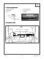
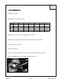
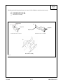
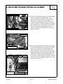
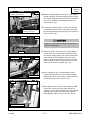
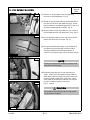
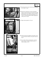
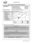
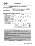
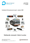
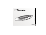
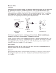
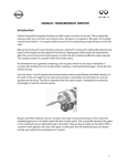
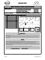
GENUINE PARTS
iPOD INSTALLATION INSTRUCTIONS
1. DESCRIPTION: iPod
2. PART NUMBERS:
3. MODEL APPLICATION:
4. iPOD
No.
1
2
3
4
5
6
7
8
9
10
11
12
iPod Gateway Module Kit (Nissan 2004-05)
999U7-VR000
iPod Gateway Module Kit (Infiniti 2004-05)
999U7-VR001
N-Bus harness for iPod Gateway
999U7-VS000
N-Bus harness for [optional] SAT Radio
999U7-VS001
ARMADA, TITAN & QX56 (2004~5) w/ SAT Pre-wired N-Bus Harness
GATEWAY MODULE KIT CONTENTS (999U7-VR000/1):
Qty
Parts
1
iPod Gateway Module
12
Cable tie (8")
6
Cable tie (15")
1
Double-Sided Tape
9
Foam Tape
1
Grommet
1
Alcohol Wipe
1
iPod Cable
1
Quick Reference Card
1
Owners Manual
1
Service Info Insert
1
Critical Installation Info
Parts View
CAUTION
• Cut the excess cable tie(s) as flush with the head as possible. Face head of cable tie away from sheet metal
and other objects.
• Use caution when removing/re-installing interior components to avoid damage, scratches, or breaking of
mounting clips.
NOTE
• This is a universal installation kit so all parts may not be used.
• Refer to the vehicle specific SAT radio Installation Instructions on ASIST.NET for further information.
• Ensure the Owners Manual and Quick Reference Card are placed in the customers glove box.
• Check the customer's iPod to make sure it has the most current software version before starting the install.
(www.apple.com/ipod)
• In the event the iPod system needs to be serviced, order the iPod Service Kit below.
iPod Gateway Service Kit
3.14.06
999U7-VS002SP
284-9798-100-I1
ARMADA,
QX56 &
TITAN
5. TOOLS & MATERIALS REQUIRED:
1.
2.
3.
4.
Phillips screwdriver (#2)
Electrical tape
Masking tape
Drill
5.
6.
7.
8.
1/8”, 11/16” drill bits
¼” driver w/ 8mm socket
Plastic Pry bar
PGF Stick
PGF Stick
6. INSTALLATION OUTLINE:
Vehicle Front
Satellite Radio
[optional]
999U7-VS001 [optional]
iPod Gateway
Module
999U7-VS000
SAT Pre-wired N-Bus harness
Head Unit
iPod (glove box)
iPod cable
Fig. 1
3.14.06
2/11
284-9798-100-I1
ARMADA,
QX56 &
TITAN
7. VEHICLE PREPARATION:
(1) Apply parking brake.
(2) Record the customer radio presets.
Bank
1
2
3
4
5
6
7
A
B
C
(3) Make sure that the shift lever is engaged in the "P" position.
(4) If equipped, move the accelerator and brake pedals to the front most position.
(5) Turn the ignition switch OFF
(6) Open engine hood.
(7) Disconnect the battery negative terminal to prevent short circuits during installation.
(8) Locate N-BUS harness on the speaker amplifier bracket. Fig. 2
Fig. 2
3.14.06
3/11
284-9798-100-I1
ARMADA,
QX56 &
TITAN
(9) Remove the following interior parts as shown in Fig. 2 (Refer to vehicle service manual)
a)
b)
c)
Instrument lower cover LH
Instrument lower cover RH
Glove Box assembly
alignment pin
b)
a)
clip points
clip points
alignment pin
Instrument lower cover RH
Instrument lower cover LH
c)
Glove Box assembly
Fig. 3
3.14.06
4/11
284-9798-100-I1
8. CABLE ROUTING (iPOD GATEWAY & [OPTIONAL: SATELLITE RADIO]):
ARMADA,
QX56 &
TITAN
optional cable for SAT radio
Front of Vehicle
Fig. 4
pre-wired N-Bus connector
(1) Connect corresponding connector of the iPod gateway
harness to the vehicle's prewired N-Bus. From
vehicle's N-Bus prewired connector start by routing
down to lower center console. Route cable on
passenger side of (above) large harness near center
console. [Optional: Connect corresponding connector
of the Satellite harness to the correct tuner connector.
Route cable the same as iPod gateway harness.]
Secure the cable(s) to the large harness with one (1)
cable tie. Fig. 4 & 5
Front of Vehicle
large harness
cable tie
N-bus cable(s) (routed
above large harness)
N-bus cable(s)
mounting bracket
for the glove box
3.14.06
foam tape
Fig. 5
cable tie foam tape
(2) Route cable down to lower vent. Before routing cable
further add two (2) pieces of foam tape to outer edge
of the vent on both sides to prevent vibration noise.
Route to other side of center console through cavity
below vent opening. Add one (1) piece of foam tape to
the edge of the metal framing where the cable(s) exit
near the vent. [Optional: Route Satellite cable in the
same fashion.] Secure cable(s) to nearby metal framing
with one (1) cable tie threaded through the hole in the
metal framing. Fig. 5 & 6
Front of Vehicle
Fig. 6
5/11
284-9798-100-I1
Route cable(s) above small mounting
bracket for the glove box.
ARMADA,
QX56 &
TITAN
Fig. 7
(3) Before routing cable(s) into C-channel, route cable(s)
behind and above small mounting bracket for the glove
box. Route cable(s) up towards C-channel in the glove
box's cavity. [Optional: Route Satellite cable in the
same fashion.] Fig. 7
Ensure cables are stacked
vertically in this region.
(4) If routing the satellite radio bus cable ensure that they
are stacked vertically directly to the right of the glove
box mounting bracket to the point they are inserted into
the C-channel. Fig. 7
Fig. 8
foam tape
CAUTION
If cables are not orientated vertically the glove box will
not fit nor shut properly.
cable ties
nearby module
N-bus cable(s)
cable tie
Fig. 10
Fig. 9
harness cluster
(5) Add one (1) piece of foam tape to the sharp edge of
the lower part of C-channel where cable(s) will enter
the channel. Route cable into C-channel towards RH
door. [Optional: Route Satellite cable in the same
fashion.] Attach two (2) cable ties around C-channel.
While cinching the left most cable tie ensure that the
cables remain vertically stacked. Fig. 7 & 8
(6) Route cable(s) out of C-channel between nearby
module and large harness cluster. [Optional: Route
Satellite cable in the same fashion.] Secure with one
(1) cable tie to the harness cluster. Fig. 9
iPod gateway bus
(7) Route behind harness cluster and through rear of RH
dash frame. Continue to route cable towards the
opening in dash to the right of the fuse panel and leave
dangling until installing the module later. [Optional:
Route Satellite cable in the same fashion.] Fig. 10
[Optional Satellite bus]
3.14.06
6/11
284-9798-100-I1
ARMADA,
QX56 &
TITAN
9. CABLE ROUTING (iPOD CABLE):
(1) Using a 1/8" bit, drill a pilot hole in the upper part of the
glove box 14mm +/-1mm (0.55in) from both front and
right walls of the box. Then use an 11/16" drill bit to
open up the hole. Fig. 11
Fig. 11
14 mm
CAUTION
Accurate measuring is important in this step due to
possible interference issues with the iPod cable and
the opening/closing of the glove box.
glove box latch
release handle
Fig. 12
frame of glove
box cavity
iPod cable mark
(2) Mark the iPod cable 762mm +/- 25mm (30in +/- 1in)
from the iPod connector (rectangular connector). Start
routing iPod cable from inside of glove box with DIN
connector end (round connector). Route out of glove
box through the drilled hole. Place split grommet over
wire and feed into drilled hole in glove box. A PGF
stick or other plastic prying tool may be helpful. Fig. 11
nearby harness
iPod cable
cable ties
Fig. 13
cable ties
position 1" to left of hole
(3) Route cable up and over upper frame of glove box
cavity. Continue routing down and to the right of the
glove box cavity. Secure with one (1) cable tie on the
iPod cable mark made earlier to nearby harness. Fig.
12
(4) Follow bus cables to the iPod gateway mounting
location allowing enough room for a connection to the
module. Any extra cable can be wrapped into a 8"-9"
bundle. Wrap electrical tape around the bundle in two
(2) places for at least two (2) revolutions and secure
with (2) cable ties behind the nearby large harness.
Fig. 13
(5) Cut one (1) piece of foam tape in half width-wise. Cut
slit in middle of foam tape piece 1/3 of the length.
Position the iPod cable 25mm (1") to the left measuring
from the center of the left most hole in the upper frame.
Place piece of foam tape over iPod cable and secure to
upper frame of glove box cavity with the slit facing the
front of the vehicle. Fig 14-1 & 14-2
NOTE
Fig. 14-2
When re-installing the glove box any slack needs to be
pulled out. When lifting the glove box in place pull the
cable from the inside of the glove box.
(6) Temporarily put the glove box back into place.
Fig. 14-1
(7) With glove box in place, and the slack pulled into the
box, the distance from the grommet in the glove box to
the iPod end of the cable should be 560mm +/- 25mm
(22in +/- 1in).
foam tape
3.14.06
7/11
284-9798-100-I1
ARMADA,
QX56 &
TITAN
10. iPOD GATEWAY MOUNTING:
Fig. 15
(1) Connect all routed cables to the corresponding
terminals of the iPod gateway. Fig. 15
(2) Thread the two (2) large cable ties through the holes in
the chassis from left to right (label facing up). Ensure
that the cable ties are pulled through with no slack and
the head is pulled right up to module. Fig. 16
(3) Attach another two (2) large cable ties, one to each of
the threaded cable ties from the previous step. Fig. 16
Fig. 16
(4) Cut the threaded cable ties from step 2 even with the
head of the cable ties from step 3. Fig. 16
(5) Using the provided alcohol wipe, clean the bottom of
the module and corresponding mounting location.
Attach provided double-sided tape to bottom of
module. Do not peel off tape liner on the other side yet.
connectors
Fig. 17
NOTE
Partially removing the door molding may help provide
more room for maneuvering.
Fig. 18
(6) Feed both large cable ties around metal frame as
shown. Keep track of the upper and lower cable tie.
Feed upper cable tie through small hole in frame and
connect to head of cable tie for a few clicks. Feed
lower cable tie around frame under the small tab and
connect to cable tie head for a few clicks.
Fig. 17, 18 & 19
CAUTION
Ensure that the large cable ties do not wrap around
any other cables or objects.
small tab
3.14.06
8/11
284-9798-100-I1
ARMADA,
QX56 &
TITAN
Fig. 19
(7) Now the tape liner can be removed and the assembly
put into place. Fig 20
(8) Position the assembly just in front of and at equal
height as the top of the hole in the metal frame. Apply
equal pressure to the module for at least 20 seconds.
After attaching to metal frame let the module sit for 5
minutes to ensure good adhesion before applying any
shear pressure. Fig. 20
position at equal height and to
the front of these imaginary lines
Fig. 20
(9) Tighten the large cable ties. Fig. 20
small tab
bolt to attach
ground cable
Fig. 21
(10) Take the ground wire tapped off of the N-bus harness
and route towards lower bolt securing the fuse panel.
Fig. 21
(11) Use an 8mm socket to remove the bolt. Insert the
eyelet connector. Tighten the bolt back down to
secure the eyelet. Fig. 21
ground cable
3.14.06
9/11
284-9798-100-I1
ARMADA,
QX56 &
TITAN
11. OPERATION CHECK:
(1) Connect the battery negative terminal.
(2) Turn vehicle ignition switch to the "ACC" position.
(3) Reference the vehicle specific Satellite Radio Installation Instructions for further information. If Satellite
radio was part of installation turn radio on then select satellite radio mode. Acquiring (Sirius) or Loading
(XM) will display for a while. If not, move vehicle to outside and try again.
(4) If Satellite radio was part of installation tune to preview channel (XM: channel "1" / Sirius: channel "184")
to make sure receiving preview channel correctly. For Sirius tuner installations the preview channel may
not be accessible. For further information reference the Operation Check section of the vehicle specific
Satellite Radio Installation Instructions.
(5) Confirm proper audio operation. (AM / FM / SAT / TAPE / CD)
(6) Confirm accelerator pedal function per service manual.
(7) If no iPod is present the head unit display should show "NO IPOD". If an iPod is connected to the
system a check mark should be displayed on the iPod screen and audio should start playing in 5-20
d
(8) A full diagnostic tree is available on the next page for troubleshooting the system.
12. REINSTALLATION OF REMOVED PARTS:
(1) Re-install the RH Instrument Lower Cover referring to the service manual for the vehicle.
(2) Re-install all removed vehicle parts referring to the service manual for the vehicle.
CAUTION
Use caution when re-installing interior components to avoid damage, scratches, or breaking of mounting
clips. Refer to the vehicle specific service manual for more information.
(3) Clean interior of vehicle.
13. FINAL INSPECTION:
(1) Inspect the vehicle interior and exterior for damage.
(2) Confirm proper operation of vehicle systems.
(3) Reset radio presets to the recorded settings.
(4) If equipped, verify proper sunroof operation and perform the reset procedure if necessary. Refer to
Service Manual requirements.
(5) Place the Owners Manual and Quick Reference Card in the customers glove box.
3.14.06
10/11
284-9798-100-I1
NISSAN IPOD INTERFACE DIAGNOSTIC FLOW CHART
1.
2.
Verify iPod module is installed by looking in glove box for iPod cable.
Confirm the audio system is otherwise OK (AM/FM/CD works normally).
Can SAT be selected on the audio system?
Push the SAT button if present. If no SAT button, push “Radio”.
NO
YES
“NO SAT” is shown on the audio display.
After pushing “Radio,” display says
AM/FM/AM
YES
YES
Does radio show:
“RADIO ID” Æ “NO IPOD”?
Check connections to iPod &
SAT modules
Connect iPod
NO
Update iPod
software to the
latest version
Check
connections to
iPod & SAT
modules
Connections Okay?
NO
Is an iPod connected?
NO
YES
Fix Connections
Is music playing from iPod?
NO
Does iPod have checkmark screen?
NO
YES
Fix
Connections
YES
NO
Disconnect & reconnect iPod
Replace iPod
module
YES
Is music playing
from iPod?
NO
YES
Is music
playing from
iPod?
YES
NO
NO
Is iPod software the
latest version?
See apple.com/ipod
Call TECH LINE
for further diagnosis
Disconnect iPod
YES
No further
diagnosis
needed
Reboot iPod
Press & Hold center button & Menu button
simultaneously until Apple Screen appears
Disconnect
iPod
Reconnect iPod
NO
NO
3.14.06
Cycle
Ignition
Does iPod have checkmark screen?
Reconnect
iPod
NOTE: When the iPod battery is very
low, it is possible that the system will
not be able to charge it. The system
may not work at all in this case. If this
occurs, please try to charge your iPod
using the iPod power adapter.
No further
diagnosis needed
Connections
Okay?
See service bulletin for Nissan
Satellite Radio Diagnostic
Information
NO
YES
Does iPod have checkmark screen?
YES
Is music playing
from iPod?
YES
No further
diagnosis
needed
11/11
284-9798-100-I1