1
www.elechouse.com
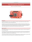
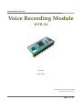
Voice Recording Module WTR‐S4 Manual Data Sheet Document Date: Apr. 20th, 2009 Document Revision: V1.4 Page 1 of 18
www.elechouse.com
Table of contents
1. FEATURES ............................................................................................................................................................3 2. FUNCTION DESCRIPTIONS...........................................................................................................................3 3. RELATIONSHIP OF FLASH ME‐ MORY & DURATION........................................................................3 4. APPLICATION DIAGRAM...............................................................................................................................3 5. PACKAGE SKETCH MAP.................................................................................................................................3 6. PIN DESCRIPTIONS..........................................................................................................................................4 7. SAMPLING RATE SETTINGS .........................................................................................................................5 8. PARAMETERS .....................................................................................................................................................5 9. MODES..................................................................................................................................................................5 9.1. KEY MODE ................................................................................................................................................5 9.1.1. RECORD ..........................................................................................................................................6 9.1.2. PLAY/STOP......................................................................................................................................6 9.1.3. NEXT ................................................................................................................................................6 9.1.4. PREVIOUS .......................................................................................................................................7 9.1.5. VOLUME ADJUSTMENT..............................................................................................................7 9.1.6. ERASE...............................................................................................................................................7 9.2. ONE KEY ONE VOICE MODE (RECORD & PLAY BY THIS SAME KEY)..................................7 9.3. THREE LINE SERIAL MODE ................................................................................................................8 9.3.1. ASSIGNMENT OF I/Os..................................................................................................................8 9.3.2. FUNCTIONS AND CORRESPONDING CODE ........................................................................9 9.3.3 VOICE ADDRESSES........................................................................................................................9 9.3.4. THREE LINE SERIAL CONTROL TIMING..............................................................................10 9.3.5. PROGRAM EXAMPLE ................................................................................................................10 10. APPLICATION CIRCUIT ..............................................................................................................................13 10.1. WTR‐S4 RECORDING MODULE INNER .........................................................................................13 10.2. PWM OUTPUT IN KEY MODE...........................................................................................................13 10.3. DAC OUTPUT IN KEY MODE............................................................................................................14 10.4. PWM OUTPUT IN ONE BY ONE KEY MODE FOR RECORDING ..............................................14 10.6. DAC OUTPUT IN ONE BY ONE KEY MODE FOR PLAYING ......................................................15 10.7. PWM OUTPUT IN THREE‐LINE SERIAL MODE ...........................................................................16 10.8. DAC OUTPUT IN THREE‐LINE SERIAL MODE.............................................................................16 11. DIAGRAM OF PACKAGE ............................................................................................................................17 12. HISTORY VERSION.......................................................................................................................................17 13. GUANGZHOU WAYTRONIC TECHNOLOGY CO., LTD. ....................................................................17 14. ABOUT US........................................................................................................................................................17 Page 2 of 18
www.elechouse.com
4M 8M 16M 32M 64M
6K 170 341 682 1365 2730
8K 128 256 512 1024 2048
12K 85 170 341 682 1365
16K 64 128 256 512 1024
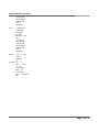
1. FEATURES C •Apply 8 bit DSP core recording chip WTR010, 16 bit ADC input, 16 bit DAC output. •Support external SPI‐FLASH (4M/Bit to 16M/Bit) •One key one voice mode (record & play by this same key) and three line serial mode. •Support Line and MIC record. •Self‐set Sampling rate from 6KHz, 8KHz, 12KHz 16KHz. •Input voltage from DC2.7V to 3.5V •Below 150uA consumption in saving power mode. •Can use in phone recording, industrial control, consumable products, toys and so on. D S C: CAPACITY D: DURATION TIME (seconds) S: SAMPLING RATE 2. FUNCTION DESCRIPTIONS Realize the recording function by our WTR chip and external SPI FLASH. With good quality sound, long recording duration and low cost. Currently, the longest recording duration is 2730 seconds for this module. WTR‐S4 module with key mode, One key one voice mode (record & play by this same key), and three line serial mode. The mode can not be change after fixed at first time programming. But the recording can be erased. You should tell us which mode you need. 3. RELATIONSHIP OF FLASH ME‐ MORY & DURATION 4. APPLICATION DIAGRAM MCU
SPI-FLASH
LINE IN
WTR-S4
MODULE
MIC IN
AUDIO OUTPUT
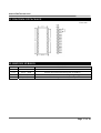
5. PACKAGE SKETCH MAP 1
2
3
4
5
6
7
8
9
10
11
12
13
14
P05
P06
P07
P15
P16
P17
RESET
AUDIO-L
SPSP+
DI
DO
CLK
GND
NC
NC
LINE
GND
MIC
P04
VCC
BUSY
VCC
P00
P01
P02
P03
CS
28
27
26
25
24
23
22
21
20
19
18
17
16
15
28PIN MODULE Page 3 of 18
www.elechouse.com
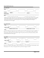
6. PIN DESCRIPTIONS PINS SYMBOL BRIEF FUNCTIONS 1 P05 KEY 6 Short press to erase the current group of voice, long press to erase all groups of voice 2 P06 Sampling rate setting
Combined P06 and P07 to set the sampling rate 3 P07 Sampling rate setting
Combined P06 and P07 to set the sampling rate 4 P15 Low voltage detecting
5 P16 Mode choosing In one key one voice mode (record & play by this same key), low level for recording, high level for playing. 6 P17 Charge 7 RESET Reset Low level to reset 8 AUDIO‐L Audio output When external amplifier, audio + 9 SP‐ Audio output When direct drive speaker, audio ‐ 10 SP+ Audio output When direct drive speaker, audio + 11 DI I/O Memory data in 12 DO I/O Memory data out 13 CLK I/O Memory clock 14 GND GND Power GND 15 CS I/O Memory CS 16 P03 Key 4/serial port data
“Previous”/serial port data in 17 P02 Key3/ serial port CLK
“Next” /serial CLK input 18 P01 Key 2 / serial port CS ‘Play/stop “/ serial port CS input 19 P00 Key 1 Record 20 VCC Power + Power input, positive, DC DC2.7V~3.5V 21 BUSY Busy output Discontinuous low level output in recording, durative low level output in playing. 22 VCC Power + Power input, positive, DC DC2.7V~3.5V 23 P04 Key 5 Four level volume adjustment 24 MIC MIC record MIC record positive input 25 GND GND MIC, Line record negative input 26 LINE Line record Line record positive input 27 NC NC NC 28 NC NC NC Page 4 of 18
www.elechouse.com
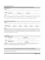
7. SAMPLING RATE SETTINGS Set sampling rate by P06 and P07, refer to following sheet. P06 P07 LOW LOW HIGH LOW LOW HIGH HIGH HIGH SAMPLING RATE 6KHz 8KHz 12KHz 16KHz 8. PARAMETERS Test conditions: DC 3.3V, 25℃, 0.5W/8Ω speaker. ITEM MIN. MAX. TYPE UNIT CONDITION
OPERATING VOLTAGE RANGE 2.7 3.5 3.3 V 25℃ I/O LEVEL HIGH 2.7 3.5 3.3 V 25℃ LOW 0 0.5 0.1 V 25℃ RECORD CONSUMPTION CURRENT ‐‐‐ ‐‐‐ 10 mA VCC=DC3.3V
PLAY CONSUMPTION CURRENT 20 200 120 mA VCC=DC3.3V
STANDBY CONSUMPTION CURRENT ‐‐‐ ‐‐‐ 120 uA VCC=DC3.3V
9. MODES WTR‐S4 with key mode, one key one voice mode (record & play by this same key) , three line serial mode. 9.1. KEY MODE In this mode, I/O functions I/O P00 P01 P02 P03 P04 P05 FUNCTION RECORD PLAY/STOP
NEXT
PREVIOUS VOLUME DELETE Page 5 of 18
www.elechouse.com
9.1.1. RECORD Remark: First negative edge start to record first group of voice. Second negative edge stop recording. Third negative edge starts to record second group of voice. Fourth negative edge stop recording. Record voice with this way. Total 256 groups of voice. During recording, BUSY sending out discontinuous low level signal. 9.1.2. PLAY/STOP Remark: First negative edge start to play current group of voice, second negative edge stop playing, third negative edge replay, fourth negative edge to stop. Play in this way, During the playing , BUSY send out durative low level signal. 9.1.3. NEXT Remark: First negative edge trigger to play second group of voice, second negative edge trigger to play third group of voice. Play to last group in this way, then next trigger is invalid. Page 6 of 18
www.elechouse.com
9.1.4. PREVIOUS Remark: First negative edge trigger to play ” N‐1” group of voice , second negative edge trigger to play “N‐2” group of voice, play to the first group of voice in this way , then next trigger is invalid. 9.1.5. VOLUME ADJUSTMENT Remark: The default volume is maximum(level 4) when power on , first negative edge turn it to level 3, second negative edge turn to level 2, third negative edge turn to level 1(mute), fourth negative edge turn to level 4 again, loop in this way . During the volume adjustment, BUSY output keep high level. Volume can be adjusted in playing or stop status. 9.1.6. ERASE Remark: Low level trigger. Short press to erase the current voice in FLASH, long press to erase all groups of voice. BUSY output always high level during erasing. 9.2. ONE KEY ONE VOICE MODE (RECORD & PLAY BY THIS SAME KEY) One key one voice mode (record &play by this same key), Choose record or play status by P16, P16 high level (play), P16 low level (record). Page 7 of 18
www.elechouse.com
When into record status, before recording start, BUSY must be Low level for 3 seconds, and make I/O P00~P05 correspond current address. And record start. P16 high level can make record stop. P16 STATUS P14 P16 HIGH LEVEL(durative)
P16 LOW LEVEL(durative) P14 HIGH LEVEL PLAY RECORDING P14 LOW LEVEL (3 seconds) PLAY START RECORD Record or play Addresses are decide by I/Os P00, P01, P02, P03, P04, P05, pull low I/O and choose relative address for record or play. I/O P00 P01 P02 P03 P04 P05 KEY K1 K2 K3 K4 K5 K6 FUNCT
ION RECORD/ PLAY ADDRESS RECORD/ PLAY ADDRESS RECORD/ PLAY ADDRESS RECORD/ PLAY ADDRESS RECORD/ PLAY ADDRESS RECORD/ PLAY ADDRESS
VOICE GROUP 1 GROUP 2 GROUP 3 GROUP 4 GROUP 5 GROUP 6
9.3. THREE LINE SERIAL MODE Three line serial mode with 3 I/Os , they are CS , DI , CLK. Timing according to SPI communication protocol. MCU control voice chip by three line serial interface. In this mode, all keys are invalid. 9.3.1. ASSIGNMENT OF I/Os MODEL WTR‐S4 I/O FUNCTIONS P00 P01 P02 P03 P04 P05 ‐‐‐ CS CLK DATA(IN) ‐‐‐ ‐‐‐ Page 8 of 18
www.elechouse.com
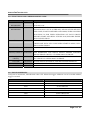
9.3.2. FUNCTIONS AND CORRESPONDING CODE FUNCTIONS CODES DESCRIPTIONS CONVENTIONAL RECORDING FAH+00H SEQUENTIAL RECORDING, TIME IS NOT LIMITED. BUSY PULLED LOW TIME RECORDING FBH+XXH XXH REPRESENT THE RECORDING DURATION, 255 SECONDS MAX. SUCH AS FBH+05H, MEANS AFTER RECEIVE THE CODE, START TO RECORD 5 SECONDS, THEN STOP.THIS FUNCTION IS FOR FIXED DURATION OF EACH GROUP. RECORD START AND BUSY PULLED LOW, RECORD FINISH, BUSY PULLED HIGH. PLAY FCH+XXH XXH REPRESENT GROUP NUMBER, SUCH AS FCH+01H PLAY GROUP ONE. BUSY PULL LOW WHEN START PLAYING, PULL HIHG WHEN FINISH. LOOP F3H+XXH LOOP PLAY. SUCH AS F3H+09H MEANS LOOP PLAY GROUP 9 ERASE(1 GROUP) FDH+XXH XXH REPRESENT THE GROUP WHICH ERASED. FDH+02H MEANS ERASE GROUP 2 . IT NEEDS 400us TO ERASE. ERASE(ALL GROUP) VOLUME F5H+00H ERASE ALL VOICE IN FLASH, ”B‐B–B” SOUND MEANS ERASE SUCCESSFULLY. NEEDS 400us TO ERASE. F2H+XXH F2+03H MEANS MAXIMUM, F2H+00H MEANS MINIMUM . STOP F4H+00H PAUSE F6+00H STOP TO RECORD OR PLAY. PAUSE TO PLAY. 9.3.3 VOICE ADDRESSES Group 255 is maximum, Hexadecimal code is FF. When the trigger addresses out of recorded address, trigger is invalid. DATA(HEX) FUNCTIONS 00H PLAY GROUP 0 01H PLAY GROUP 1 02H PLAY GROUP 2 …… …… FDH PLAY GROUP 253 FEH PLAY GROUP 254 FFH PLAY GROUP 255 Page 9 of 18
www.elechouse.com
9.3.4. THREE LINE SERIAL CONTROL TIMING The three line serial control timing is base on standard SPI communication protocol, with CS, CLK, DI, without DO. Pull low CS 400us before sending, Sending DI at CLK rising edge. 800us<CLK cycle < 5ms. Sending 16 bit one time, former 8 bit is a code, later 8bit is the address. Pull high CS when sent 16 bit out, instead to pull high when sent former 8 bit out. Timing chart as following: CS
CLK
400us
400us
DATA(IN)
Command
Address
9.3.5. PROGRAM EXAMPLE Three‐line serial C program example Crystal oscillator 11.0592MHz . MCU:AVR‐MEGA8 void spi_send(unchar ch) { unchar i; PORTD |=BIT(spi_sda); PORTD |=BIT(spi_sck); for(i=0;i<8;i++) { if((ch&0x01)) { PORTD |=BIT(spi_sda); } else { PORTD &=~BIT(spi_sda); } ch>>=1; PORTD &=~BIT(spi_sck); delay(552); PORTD |=BIT(spi_sck); delay(552); } PORTD |=BIT(spi_sda); PORTD |=BIT(spi_sck); } void main(void) Page 10 of 18
www.elechouse.com
{ …… PORTD &=~BIT(spi_cs); delay(600) spi_send(0xfc); spi_send(0x01); PORTD |=BIT(spi_cs); …… } THREE LINE SERIAL ASSEMBLER EXAMPLE ASM Crystal oscillator 4MHz MCU:AT89C2051 rec bit p1.6 play bit p1.7 cs bit p3.5 scl bit p3.7 sda bit p3.4 org 0000h ajmp main org 0030h main: mov 2fh,#00h key: jnb rec,rec1 jnb play,pla1 ajmp key rec1: acall d10ms jb rec,key jnb rec,$ clr cs acall d1ms mov a,#0f5h acall send2 mov a,#00h ; acall send2 setb cs acall d1ms clr cs acall d1ms mov a,#0fah acall send2 mov a,#00h acall send2 setb cs ajmp key rec2: clr cs acall d1ms mov a,#0f4h Page 11 of 18
www.elechouse.com
acall send2 mov a,#00h acall send2 setb cs ajmp key pla1: acall d10ms jb play,key jnb play,$ cpl 2fh.1 jnb 2fh.1,rec2 clr cs acall d1ms mov a,#fch acall send2 mov a,#00h acall send2 setb cs ajmp key send2: mov r1,#8 setb scl setb sda clr c send2a: rrc a mov sda,c clr scl acall d1ms setb scl acall d1ms djnz r1,send2a ret Page 12 of 18
www.elechouse.com
10. APPLICATION CIRCUIT 10.1. WTR‐S4 RECORDING MODULE INNER 10.2. PWM OUTPUT IN KEY MODE VOLUME
ERASE
SAMPLING RATE CHOOSING
SAMPLING RATE CHOOSING
RESET
SPEAKER
LINE RECORD IN
1
2
3
4
5
6
7
8
9
10
11
12
13
14
P05
P06
P07
P15
P16
P17
RESET
AUDIO-L
SPSP+
DI
DO
CLK
GND
WTR-S4
NC
NC
LINE
GND
MIC
P04
VCC
BUSY
VCC
P00
P01
P02
P03
CS
28
27
26
25
24
23
22
21
20
19
18
17
16
15
MIC
+3. 3V
LED
R1
C1
330
104
RECORD
PLAY/STOP
NEXT
PREVIOUS
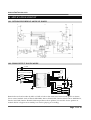
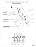
Remark: Record can be taken by MIC or LINE or both at the same time. In this mode, pull low relative I/O to control module. Such as P00 for RECORD, P01 for PLAY/STOP, P02 for NEXT, P03 for PREVIOUS, P04 for VOLUME, P06 for ERASE. PWM output direct drive speaker, SP+ and SP‐ are for speaker on module. BUSY is high level in standby, low level in playing or recording. Page 13 of 18
www.elechouse.com
10.3. DAC OUTPUT IN KEY MODE VOLUME
ERASE
LINE RECORD IN
SAMPLING RATE CHOOSING
SAMPLING RATE CHOOSING
RESET
VDD
C3
SPEAKER
250uF
5
C4
0.05uF
8
1
7
C2
104
6
3
LM386
2
10K
1
2
3
4
5
6
7
8
9
10
11
12
13
14
P05
P06
P07
P15
P16
P17
RESET
AUDIO-L
SPSP+
DI
DO
CLK
GND
NC
NC
LINE
GND
MIC
P04
VCC
BUSY
VCC
P00
P01
P02
P03
CS
28
27
26
25
24
23
22
21
20
19
18
17
16
15
MIC
+3.3V
LED
R1
C1
330
104
RECORD
4
WTR-S4
PLAY/STOP
R2
10
NEXT
PREVIOUS
Remark: Record can be taken by MIC or LINE or both at the same time. In this mode, pull low relative I/O to control module. Such as P00 for RECORD, P01 for PLAY/STOP, P02 for NEXT, P03 for PREVIOUS, P04 for VOLUME, P06 for ERASE. In DAC output, AUDIO‐L to amplifier, audio GND to module GND. BUSY is high level in standby, low level in playing or recording. 10.4. PWM OUTPUT IN ONE BY ONE KEY MODE FOR RECORDING 音量
擦除
采样率选择
采样率选择
复位键
扬声器
1
2
3
4
5
6
7
8
9
10
11
12
13
14
R2
R3
100K
100K
P05
P06
P07
P15
P16
P17
RESET
AUDIO -L
SPSP+
DI
DO
CLK
GND
NC
NC
LIN E
GN D
M IC
P04
VCC
BUSY
VCC
P00
P01
P02
P03
CS
W TR-S4
VCC
线路录音输入
28
27
26
25
24
23
22
21
20
19
18
17
16
15
麦克风
+3.3V
LED
R1 470
录音
C1
播放/暂停
104
下一曲
上一曲
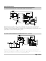
Remark: Record can be taken by MIC or LINE or both at the same time. Cathode‐pulsed P00 start to record the first voice, trigger it again to stop recording. The third trigger, start to record the second voice record, etc. can record 8 paragraphs voice. You can trigger P02, P03 to play back the recorded voice. Keep low level 1 second can delete the current voice, keep 5 second to delete all of voice. Page 14 of 18
www.elechouse.com
10.5. PWM OUTPUT IN ONE BY ONE KEY MODE FOR PLAYING 第5段
线路录音输入
第6段
1
2
3
4
5
6
7
8
9
10
11
12
13
14
第7段
第8段
复位键
扬声器
P05
P06
P07
P15
P16
P17
RESET
AUD IO-L
SPSP+
DI
DO
CLK
GN D
NC
NC
LIN E
GND
M IC
P04
VCC
BUSY
VCC
P00
P01
P02
P03
CS
28
27
26
25
24
23
22
21
20
19
18
17
16
15
麦克风
+3.3V
R1 470
LED
第1段
C1
第2段
104
第3段
W TR-S4
第4段
Remark: Record can be taken by MIC or LINE or both at the same time. Connect P16 to GND, and RESET the WTR‐S4 module can change record mode to play mode. In play back mode, P00~P05 responding to 8 paragraphs recording voice. PWM drive speaker directly. Signal output from SP+、SP‐ to speaker. BUSY at low level and LED lit during playing. 10.6. DAC OUTPUT IN ONE BY ONE KEY MODE FOR PLAYING 第5段
线路录音输入
第6段
第7段
第8段
复位键
VDD
扬声器 C3 250uF
5
C4
0.05uF
R2
8
1
6
C2 104
3
2
7
4
LM 386
10K
1
2
3
4
5
6
7
8
9
10
11
12
13
14
P05
P06
P07
P15
P16
P17
RESET
AUDIO -L
SPSP+
DI
DO
CLK
GN D
W TR-S4
NC
NC
LIN E
GN D
M IC
P04
VCC
BUSY
VCC
P00
P01
P02
P03
CS
28
27
26
25
24
23
22
21
20
19
18
17
16
15
麦克风
+3.3V
LED
R1 470
第1段
C1
第2段
104
第3段
第4段
10
Remark: Record can be taken by MIC or LINE or both at the same time. Connect P16 to GND, and RESET the WTR‐S4 module can change record mode to play mode. In play back mode, P00~P05 responding to 8 paragraphs recording voice. In DAC output, Signal output from SP+ to amplifier, audio GND to module GND. BUSY at low level and LED lit during playing. Page 15 of 18
www.elechouse.com
10.7. PWM OUTPUT IN THREE‐LINE SERIAL MODE LINE RECORD IN
1
2
3
4
5
SAMPLING RATE CHOOSING 6
7
8
SPEAKER
9
10
11
12
13
14
SAMPLING RATE CHOOSING
P05
P06
P07
P15
P16
P17
RESET
AUDIO-L
SPSP+
DI
DO
CLK
GND
NC
NC
LINE
GND
MIC
P04
VCC
BUSY
VCC
P00
P01
P02
P03
CS
28
27
26
25
24
23
22
21
20
19
18
17
16
15
MIC
+3.3V
R1
LED
330
C1
104
+3.3V
CS
WTR-S4
CLK
MCU
DATA(IN)
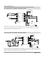
Remark: MCU control WTR‐S4 to record or play by CS, CLK, DI, including conventional record and time record. Record can be taken by MIC or LINE or both at the same time. PWM output direct drive speaker, SP+ and SP‐ are for speaker on module. 10.8. DAC OUTPUT IN THREE‐LINE SERIAL MODE LINE RECORD IN
SAMPLING RATE CHOOSING
SPEAKER C3
5
250uF
C4
0.05uF
R2
10
1
2
3
4
VDD
5
SAMPLING RATE CHOOSING 6
6
7
1
C2 104
3
8
8
LM386
9
2
10
7
11
4
10K
12
13
14
P05
P06
P07
P15
P16
P17
RESET
AUDIO-L
SPSP+
DI
DO
CLK
GND
NC
NC
LINE
GND
MIC
P04
VCC
BUSY
VCC
P00
P01
P02
P03
CS
28
27
26
25
24
23
22
21
20
19
18
17
16
15
MIC
+3.3V
LED
R1
330
C1
104
+3.3V
CS
WTR-S4
CLK
MCU
DATA(IN)
Remark: Remark: MCU control WTR‐S4 to record or play by CS, CLK, DI, including conventional record and time record. Record can be taken by MIC or LINE or both at the same time. DAC output external amplifier, audio+ from “AUDIO‐L”, audio‐ from module GND. Page 16 of 18
www.elechouse.com
11. DIAGRAM OF PACKAGE Unit: mm 12. HISTORY VERSION VERSION DATE DESCRIPTION V1.0 Oct. 9th, 2008 ORIGINAL V1.1 rd
Amend the internal block diagram of WTR‐S4 V1.2 V1.3 Oct. 3 , 2009 nd
Increase switch control mode and package diagram th
Amend the description of one by one key mode Mar. 22 , 2009 May. 14 , 2009 Page 17 of 18