1
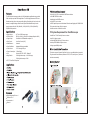
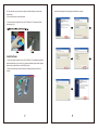
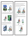
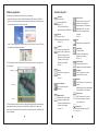
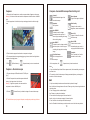
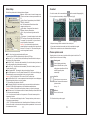
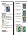
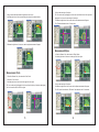
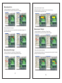
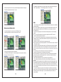
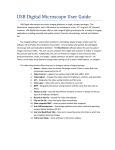
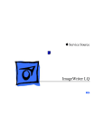
SmartScope 5M
REV.C
The 200X digital microscope provides a 10~200X adjustable magnification range, and the
500X microscope provides 500X magnification. The built-in high-performance LEDs can
illuminate an object without using any auxiliary lighting. By adjusting the focus knob on the
camera, the magnified image can be viewed, captured and recorded directly from the
computer screen with with VGA (640x480)、XGA (1024x768)、QXGA (2048x1536)、
5M(2592x1944) resolution.
● Image Sensor:
1/4” Color CMOS image sensor
● Effective Pixels:
2592 (H) x 1944 (V) pixels (5M for Hardware Snapshot MAX.)
● Signal Output:
Serial data for USB standard compliant 2.0
● Gain Control:
Auto Gain Control (AGC)
● White Balance:
Automatic
● Snap Shot Mode:
Hardware/Software controllable
● Power Source:
5VDC through USB port
● Power Consumption: 260mA (Max.)
● O/S:
Windows XP SP3 / VISTA / Windows 7
● Magnification:
200X digital microscope:10X~200X range
500X digital microscope:500X
● CE, FCC and RoHS Compliant
Digital Microscope Device x 1
Software CD x 1
User manual x 1
Stand x 1
● Pentium 4 3.0G CPU or equivalent AMD Phenom II above
● 1024 MB DDR RAM or above
● Northbridge Intel i945GZ or above
● One USB 2.0 port or above
● 2D/3D Graphics processor with Hardware Transform and lighting with 512MB VRAM
VGA system with at least 16bit color support
● Monitor resolution: 1280x1024 or above
PC System Requirement For Dual Microscope
● Intel® Core™2 Duo Desktop Processor or above
● Intel G31 chipset or above
● Graphic:NVIDIA® GeForce® 7 series or above
● Memory:DDR2 800MHz 1GByte or above
● Storge space:30MByte above
This device supports “Universal Video Class” driver, so no additional driver is required.
Plug the camera in and Windows (Windows XP SP3, VISTA, and System 7) will install
the driver automatically.
b.) Press the holder, pull up and down to adjust the distance between the microscope
and the object.
c.) Place the microscope on the stand holder.
2. Insert the software installation CD into the CD-ROM drive. The software will install
automatically.(fig.1)
Install Software
1. Insert the software installation CD into the CD-ROM drive. The installation program will
appear automatically on your screen. (If the software installation program doesn’t appear,
please double click AutoRun.exe in the CD-ROM folder)
2. Please click SmartScope Viewer 5M button for installing SmartScope Viewer 5M
software.
3.Install the SmartScope Viewer 5M program and restart the computer.
4. Double Click the【SmartScope Viewer 5M】software, and the image will show up.(fig.3)
5. Place the camera on or above the object to be viewed.(fig.4)
10. When magnifingan object, adjust the focus knob slightly to the left and move the
digital microscope up and down until a clear image is obtained.(fig.9)
11. If the object has too much relief or if a higher magnification (bigger image) is
unnecessary, lift the digital microscope a little bit and adjust the focus knob slightly to
the right until a clear image is obtained.(fig.10)
6. Tilt the digital microscope slightly when viewing the object in order to get 3D image.(fig.5)
7. The digital microscope can be used to get the desired image size preferred by the user’s.
The closer you put the digital microscope to the object, the bigger image will be.(fig.6)
12. If the object is too dark or bright, adjust the light knob until you get the preferred
brightness. Turn the knlb to the right to get a brighter light and to the left to get a
dimmer light.(fig.11)
13. When using high magnification to observe a specific area of the object, placing the
digital microscope on the stand holder is recommended to obtain a clearly focused
image.(fig.12)
8. A clear focused image can be obtained by adjusting the focus knob as well as
changing the distance between the object and the digital microscope.(fig.7)
9. If the image is blurred, adjust the focus knob to the right end and view the image of
the object in lower magnification first.(fig.8)
14. Use snapshot button to capture an image.(fig.13)
Software application
1. Double click the SmartScope Viewer 5M icon on your desktop.
Note:1.Be make sure to connect the Digital Microscope USB cable to the USB port.
Note:2. Key in the Serial Number which can be found on the paper CD envelope or just
press the Evaluate button for a 30 day free trial.
Function Key lists:
Snapshot:
Take a picture.
(saved as a BMP file)
Hot key:F3
PS.The max resolution for
software snapshot is 2048x1536.
Record:
Capture a movie.
(saved as an AVI video file)
Hot key:F4
Note:”TV card Configuration” window will show up at the first time, click the “OK” button
and double click the MicroViewer again.
2. The SmartScope Viewer 5M window will show up and you will see the live image from
the Microscope.
Function Key
Live zone
List bar
PS.The SmartScope Viewer 5M will choose the appropriate video format automatically by
detecting the resolution of the monitor. If the resolution is 1280x1024 (or above), the
default video format is 1024x768. If the resolution is 1024x768(or below), the default video
format is 640x480.
Compare:
Compare a live image with a
picture or video, compare two
pictures or compare two live
image from two microscopes
(Please see the Compare
Chapter for more detail)
Hot key:C
Freeze:
Freeze the live image on the
screen.
Hot key:F
Save clipboard:
Copy the live image to the
clipboard.
Measurement:
Measure lines, circles, angles,
rectangles, triangles or radii.
(Please see the Measurement
Chapter for more detail)
Hot key:M
Zoom in / out:
Select the zoom-in and zoom-out
function on a live image or on
captured pictures. The maximum
magnification is 6x. The arrow
keys on the keyboard will move
the image.
Hot key:+、-
Play :
Playback the last recorded video.
Video Setup:
The setup window.
(Please see the Video Setup
Chapter for more detail).
Hot key:V
Video Quality:
Change the video value for
brightness, contrast and saturation.
Crosshair:
Click "Crosshair icon” to add a
crosshair to the live video.
Manual:
Click "Manual icon” to open the user’s
manual.
(Warning: Make sure you already have
“Adobe reader” in your computer.)
Zoom screen:
Click "full screen icon" or double
click the live image, it will switch
to full screen mode.
Power Off:
Close SmartScope Viewer 5M.
Hot key:X
Compare - Second Microscope Function Key List
Compare
1. Please click the Compare button, and the compare window will appear on the screen.
Warning: For the best results screen resolution requirement should be at least 1440x900
pixel
2. A live image shows in the left side, and you can drag a picture in the list bar to right
zone.
Camera 2:
Enable/Disable the image of the
second microscope.
Save clipboard:
Copy the live image to clipboard.
Snapshot:
Take a picture.
Video Quality:
Change the video value for
brightness, contrast and saturation.
Save BMP HR:
Combine the two live images
horizontally and take a picture. It
doesn’t support combining live image
with an existing image.
Save BMP VT:
Combine the two live images vertically
and take a picture. It doesn’t support
combining live image with an existing
image.
3. The left side also supports freeze function to compare two images.
Print Dual Camera:
Print live images from two
microscopes.
4. The compare window also supports dragging any pictures to the left and right sides to
compare two existing pictures.
5. Click
(Go Back button) or
(Compare button) to return to normal mode.
Compare - Dual microscope
1. Plug two microscope USB cables into the PC USB ports.
(fig.1)
2. Click the Compare button, and the compare window will
show up.Live image shows in the left zone.
Warning: To get better operation, the screen resolution
requirement is at least 1440*900 pixel.
3. Click the
(Camera 2 button) to refresh the image of the second microscope.
PS.The 2nd Microscope only supports Snapshot, recording and preview image functions.
4. After comparison, click
Save AVI 2:
Capture AVI video files from the
2nd microscope.
Save AVI HR:
Combine the two movies
horizontally and save a movie. It
only supports 640*480 resolution.
Crosshair:
Click "Crosshair icon” to add a
crosshair to the live video.
(Compare button) to back normal mode.
Notes:
1.If you close SmartScope Viewer 5M on compare mode, it will automatically enter compare
mode next time.
2.The resolution of the 2nd microscope will change automatically when you change the
resolution of the first microscope.
Q&A
1. Why the combined picture become distorted when I preview the image?
Ans: It will distort the image because of the ratio. Please go to the picture saving location and
check the picture.
2. Can I full page print the combined image?
Ans: Please set up the printer orientation.
3. Does the 2nd microscope support full-screen function?
Ans:No, only the 1st microscope supports full-screen function.
4. Can I switch the 1st microscope and 2nd microscope?
Ans:Yes. Disable the 2nd microscope, and choose the source in the video setup window.
10
Video Setup
Click the Setup button and the following window will appear:
1 Source:Allows a user to choose the image source
if there is more than one microscope connected to the
1
PC.
2
2 Video Format:Supports three options: 640x480 /
3
1024x768 / 2048x1536.
Note: The Snapshot and Record format will be
4
5
changed at the same time.
3 Video Adjust:Changes the Video values for
brightness, contrast, and saturation.
6
4 AVI:Set up the video saving location and file
name.
5 Time Lapse:If you need time-lapse function, check
7
the “Time Lapse “box and select the time-lapse rate.
8
9
For example, if you choose"60:1" only one second of
10
11
every 60 seconds will be recorded.
12
Warning: If you choose the time-lapse function,
13
please make sure the recording time is longer than the
14
ratio time. EX: Choose “60:1”, the real recording time
must be longer than 60 seconds.
BMP:Set up the picture saving location and file name.
If you want to save JPEG files, please check the “Save as JPEG” box.
7 Always On Top:If you check this box, the SmartScope Viewer 5M window is always on
the top layer of all software windows.
8 Record On The Fly:Record the video immediately. If the box isn't marked, you have to set
up the file name and saving location before recording.
9 Play On The Fly:Play the latest video immediately. If the box isn't marked, you have to
choose a video file to play.
10 Show Snapshot BMP:After snapshot, the preview window will appear.
11 Use AVIDecompressor:If the OS is below Windows XP SP2, the live zone will display an
abnormal image in some computers. Mark this box to solve this problem.
Warning: If your OS is Windows XP SP3 or above, DO NOT mark this box.
12 Use Intel 8xxG/9xxG VGA:In some computers with an Intel chip,the live zone displays an
abnormal image. Mark this box to solve this problem.
PS.The resolution will be limited to 1024x768.
13 HW Snapshot 2592x1944:Mark the box and you can save the picture with maximum
resolution of 2592x1944(5-mega)when you click the hardware snapshot button.
Warning: It will take 5~6 seconds to save a picture, please not to move the microscope.
14 Full Screen mode:If the full screen mode box is marked, SmartScope Viewer 5M will start
on full-screen mode automatically.
4:3:Live video zone will remain in a 4:3 aspect ration. This mode is necessary for the
measurement function.
FULL:The entire screen will display live video. The aspect ratio may not be correct, so
live images my appear distorted.
ICON:The Screen will be filled with the SmartScope Viewer 5M window, so all function
buttons will be visible. In this mode,the video image will be expanded and it is not correct for
the measrurement function.
6
11
Crosshair
1. On the live mode, click the crosshair button
and the crosshair will appear(fig.14):
2. You can position the crosshair by clicking the right button.(fig.15)
(fig.14)
(fig.15)
3. Capture the image, and the crosshair will show in the photo.
4. If you want to deactivate the crosshair, just click the crosshair button again.
5. Right click the crosshair button, the crosshair will back to midpoint.
Preview picture mode
Drag the picture to the live zone or just double click the picture in the list bar. The
Image will show in the live zone for editing.
Drawing mode:
Click the Drawing mode button,
Microsoft Paint will show up. After
editing, please close Microsoft Paint,
and the image will update
automatically.
Save file:
Click this button to save as a new
file.New file name will be renamed
by date and time.
Hot key:S.
Go Back :
Return to the live mode.
PS. Other function keys refer to page 8.
12
Measurement-Calibrate
Measurement Function
Click the Measurement button, and the measurement window will appear. The image will
be frozen. You can calibrate or measure the frozen image.
1
2
3
4
5
6
7
8
9
Instructions for the Measurement window:
1 VGA monitor size:Please select the monitor size.
2 H/V ratio:Select your monitor’s correct aspect ratio
to insure that correct measurements can be made.
3 Calibrate:Adjust the calibration.
Calibrate axis:X axis /Y axis /X-Y axis.
Reference Unit:Please select a unit of measurement
for calibration.There are three units: mm/inch/mil
4 Measure:Choose the measurement type.
Accuracy: The number is accurate up to nine decimal
points.
Mode:Select a measurement mode from the following
options: Angle / Circle / Ellipse / Line / Rectangle /
Triangle / 3DotsRadius.
5 Data of the measurement.
6 Remarks:The mode supports DateTime and Notes
for a measured image.
7 Ruler guides:Check the L-type or Cross if you want
this function.
8 Record history:Record the measurement actions. It
allows the user to delete a record or clear all history
records.
9 Choose the color of the line and words.
After finishing the measurement, click the Snapshot
button
or save key
to save the
measured picture.
13
1. Place the camera on a ruler and adjust the
focus knob untill the image is sharp.
2. Click the „Snapshot“ button to capture a
picture, then double click this picture in the list
bar.
3. Click the “Measurement” button, and the
“Calibration or Measurement” window will appear.
Note: You must calibrate again if you change the
distance, magnification, or resolution.
4. Check “Calibrate”, and choose the “Reference
Unit” that is the largest dimension visible on your
snapshot. EX: The largest dimension available
between 3 centimeter and 4 centimeter is 10
millimeter. Therefore, we choose the 10 mm as the
“Reference Unit”.
5. Hold the right button of the mouse at the 3
centimeter line and drag to the 4 centimeter line.
6. Release the right button of the mouse, and the
calibration is done. Click the
or
to go back.
7. Now you can begin measuring. Double click the
picture in the list bar or just place the microscope
on the object and click the “measurement” button.
Measurement-Angle
1. Mark the “Measure” box. Then select the “Angle” Mode. Set the “Accuracy” to the
number of decimal points you want to use.
2. Hold the right button of the mouse at the first point.
14
3. Drag to the left side and release the right button of the mouse.
4. Hold the right button of the mouse and drag to the other side counterclockwise.
4. Drag to the lower right of the object.
PS. You can aim easily by aligning the X axis cross line with the bottom of the object and
aligning the Y axis cross line with the right of the object.
5. Release the right button of the mouse, and the circle measurement will appear.
The “D” means diameter and the “A” means area.
5. Release the right button of the mouse, and the angle measurement will appear.
Measurement-Ellipse
1. Check the “Measure” box, then select the “Ellipse” Mode.
2. Hold the right button of the mouse at the upper left of the object.
Measurement-Circle
1. Check the “Measure” box, then select the“Circle” Mode.
2. Check the “Cross” funtion.
3. Hold the right button of the mouse at the upper left of the object.
PS. You can aim easily by aligning the X axis cross line with the top of the object and aligning
the Y axis cross line with the left of the object.
15
3. Drag to the lower right of the object.
4. Release the right button of the mouse, and the ellipse measurement will appear.
The “D1” means X axis diameter, “D2”means Y axis diameter, and “A” means area.
16
Measurement-Line
1. Check the “Measure” box, then select the “Line” Mode.
2. Hold the right button of the mouse at the left side of the object.
3. Drag to the right side of the object.
4. Release the right button of the mouse,and the line measurement will appear. The
number means the length.
3.Drag to the lower right of the object.
4.Release the right button of the mouse and the rectangle will show up.
The number means the length x width = area.
Measurement-Triangle
1. Check the “Measure” box, then select the “Triangle” Mode.
2. Hold the right button of the mouse at the first point of the object.
Measurement-Rectangle
3. Drag to the second point and release.
1. Check the “Measure” box, then select the “Rectangle” Mode。
2. Hold the right button of the mouse at the upper left of the object.
4. Immediately hold the right button of the mouse again at the second point of the object,
then drag to the third point of the object.
17
18
5. Release the right button of the mouse, and the Rectangle measurement will appear.
The number means the base x length / 2 = area.
5. Release the right button of the mouse, and the arc measurement will appear.
The “R” means radius , “A” means angle, and the “L” means arc.
Q&A
Measurement-Radius/Arc
1. Check the “Measure” box, then select the “3DotRadius” Mode.
2. Hold the right button of the mouse at the first point of the arc.
3. Drag to the second point of the arc and release.
4. Immediately hold the right button of the mouse again at the second point of the arc ,
then drag to the third point of the arc.
19
1. After inserting the software installation CD into the CD-ROM drive, why doesn’t the installation
install automatically?
ANS:Due to the operation system security, many system softwares disable the CD-R / USB
Autorun function. Please double click the CD-ROM drive on your computer, and click the
AUTORUN.EXE file.
2. Why does the image lag after I check the Use AVIDecompressor box on the Video Setup
window?
ANS:The Use AVIDecompressor function doesn’t support Windows XP SP3 or above.
3. Why the measurement number is incorrect?
ANS:You need to use the Calibrate function on the measurement window before making a
measurement. Also if you change the focal distance or height of the object you will need to use
the Adjust function again.
4. Why does the monitor “twinkle” under the measurement mode?
ANS: Set the system using the following steps:Start→Control Panel Home→System→Advanced
→Performance→Setting
Then release the “Show shadows under windows” and ”Show window contents while dragging.”
5. Why does the recording file show an error message when I open the time-lapse function?
ANS: If you open the time-lapse function, please make sure the recording time is longer than the
ratio time.
EX: Choose 60s:1s, the real recording time must be longer than 60 seconds.
6. Why do the LED lights will go out automatically while recording?
ANS: Under Windows 7, the “power saving” function will turn off the LED lights automatically,
please set the system by the following steps: Start→Control Panel→System and Security→
Power Options→Select a power plan
Click the “Show additional Plans” arrow, and choose the “High performance.”
7. After installing the SmartScope Viewer 5M, why the SmartScope Viewer doesn’t work
anymore?
ANS: Please install the upgrade version of SmartScope Viewer by the following steps: A.Insert
the SmartScope Viewer 5M CD into the CD-ROM drive. B.Click the “Install SmartScope Viewer”
button on the installation program and the latest SmartScope Viewer will install automatically.
8. I can’t install the SmartScope Viewer 5M because of the antivirus software protection. How to
solve this problem?
A: Your antivirus software may quarantine the SmartScope Viewer 5M because the software
thought it was a virus. Please uninstall the antivirus software, install the SmartScope Viewer 5M,
and install your antivirus software again. Or you can add SmartScope Viewer 5M to your
antivirus whitelist.
20